

Page 1
Service Manual – R410A Models
A Series (Electronic Controls)
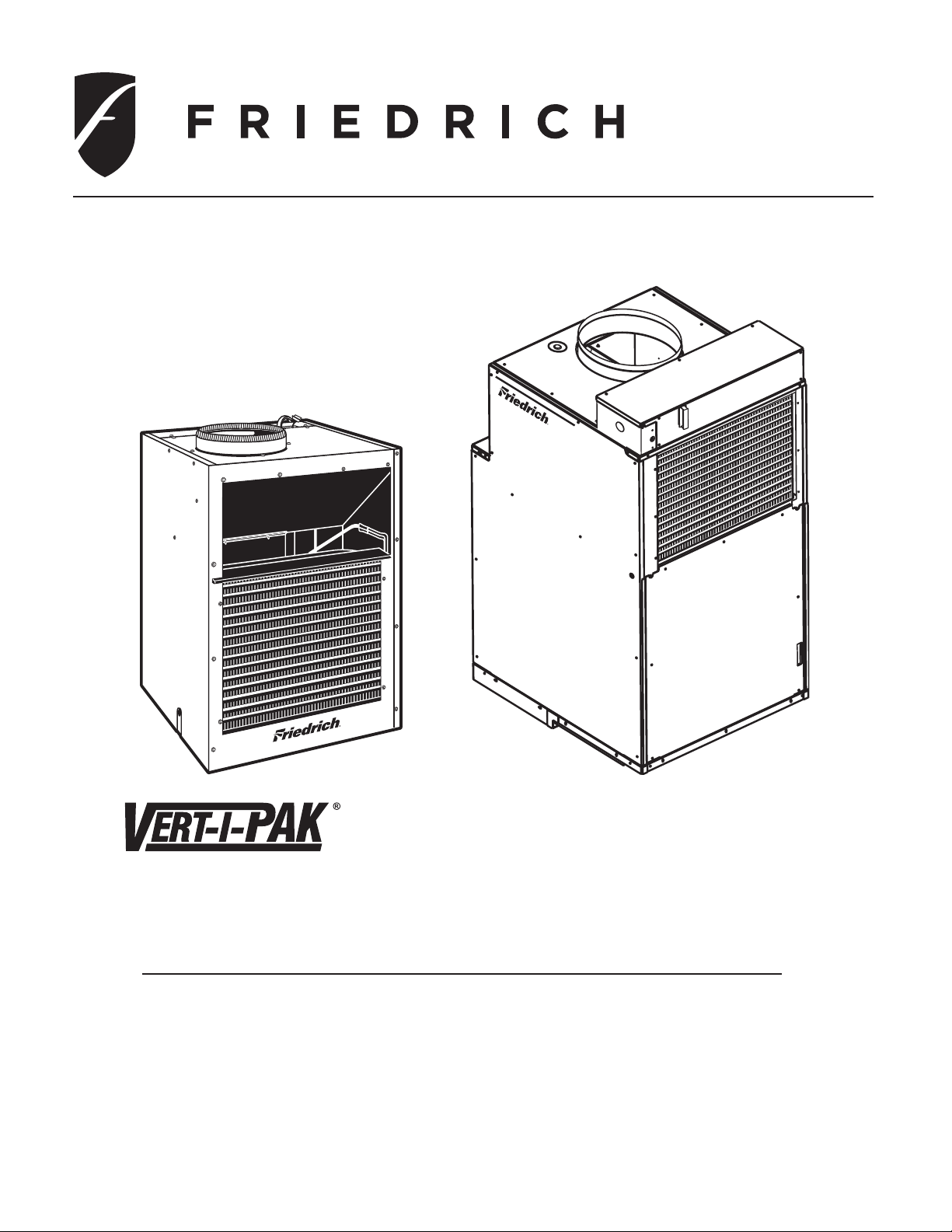
Single Package Vertical Air Conditioning System
L Sufx Models
V(E, H)A09K25L-* V(E, H)A09K34L-* V(E, H)A09K50L-*
V(E, H)A12K25L-* V(E, H)A12K34L-* V(E, H)A12K50L-*
V(E, H)A18K25L-* V(E, H)A18K34L-* V(E, H)A18K25L-*
V(E, H)A24K25L-* V(E, H)A24K34L-* V(E, H)A24K50L-*
V(E, H)A24K75L-* V(E, H)A24K10L-*
VP K- Se rv Ma n- L (1-10) *Last D igit May Vary
Page 2

INTRODUCTION
This service manual is designed to be used in conjunction with the installation manuals provided with each unit.
This service manual was written to assist the professional HVAC service technician to quickly and accurately
diagnose and repair any malfunctions of this product.
This manual, therefore, will deal with all subjects in a general nature. (i.e. All text will pertain to all models).
IMPORTANT:
FRIEDRICH AIR CONDITIONING CO.
Post Ofce Box 1540 · San Antonio, Texas 78295-1540
4200 N. Pan Am Expressway · San Antonio, Texas 78218-5212
(210) 357-4400 · 1-800-541-6645 · FAX (210) 357-4490
www.friedrich.com
It will be necessary for you to accurately identify the unit you are
servicing, so you can be certain of a proper diagnosis and repair.
(See Unit Identication.)
TECHNICAL SUPPORT
CONTACT INFORMATION
Printed in the U.S.A.
Page 3

Table of Contents
Important Safety Information ...........................................
Introduction .........................................................................
Vert-I-Pak Model Number Identication Guide ...................
Serial Number Identication Guide ....................................
Chassis Specications .......................................................
Extended Cooling Performance .........................................
Electrical Requirements .....................................................
Remote Thermostat and Low Voltage Control ..............
V-PAK Electronic Control Board Features ........................
Electronic Control Conguration .......................................
Electronic Control Error Code
Diagnostics/Test Mode .................................................
Electronic Control Features ..............................................
Checking External Static Pressure ...................................
Checking Approximate Airow ..........................................
Airow Charts ....................................................................
9-10
12-13
2-4
4
5
5
6
7
8
11
12
14
15
16
16
Capillary Tube Systems/Check Valve ..........................
Reversing Valve — Description/Operation ..................
Testing Coil ..................................................................
Checking Reversing Valves ....................................
Reversing Valve
Touch Testing Heating/Cooling Cycle .........................
Procedure For Changing Reversing Valve .............
Compressor Checks ....................................................
Locked Rotor Voltage Test ..........................................
Single Phase Connections .........................................
Determine Locked Rotor Voltage ...............................
Locked Rotor Amperage Test ......................................
Single Phase Running & Locked Rotor Amperage .....
Checking the Overload ...........................................
External Overload ........................................................
Compressor Single Phase Resistance Test ................
24
25
25
25-26
26
26-27
27
27
27
27
27
27
27-28
28
28
Components Testing ....................................................
Refrigeration Sequence of Operation ...............................
Service .............................................................................
Sealed Refrigeration System Repairs ..............................
Refrigerant Charging ........................................................
Method Of Charging .........................................................
Undercharged Refrigerant Systems ............................
Overcharged Refrigerant Systems ...................................
Restricted Refrigerant Systems .......................................
17-18
22-23
19
20
21
21
22
23
23
Compressor Replacement .....................................
Routine Maintenance ...................................................
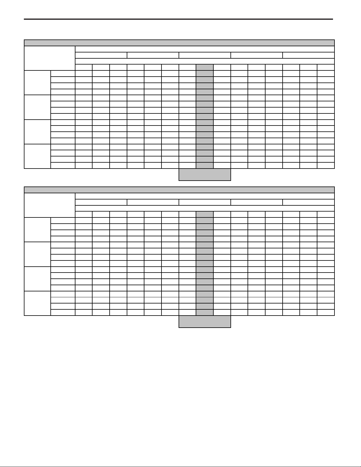
9-18 Electrical Troubleshooting Chart – Cooling .........
2-Ton Electrical Troubleshooting Chart – Cooling .......
Electrical Troubleshooting Chart – Heat Pump ...........
Refrigerant System Diagnosis – Cooling ....................
Refrigerant System Diagnosis – Heating ....................
Electrical and Thermostat Wiring Diagrams ...........
Technical Service Data ................................................
29-30
35-40
30
31
32
33
34
34
41
1
Page 4
IMPORTANT SAFETY INFORMATION
The information contained in this manual is intended for use by a qualied service technician who is familiar
with the safety procedures required for installation and repair, and who is equipped with the proper tools and
test instruments required to service this product.
Installation or repairs made by unqualied persons can result in subjecting the unqualied person making
such repairs as well as the persons being served by the equipment to hazards resulting in injury or electrical
shock which can be serious or even fatal.
Safety warnings have been placed throughout this manual to alert you to potential hazards that may be
encountered. If you install or perform service on equipment, it is your responsibility to read and obey these
warnings to guard against any bodily injury or property damage which may result to you or others.
We have provided many important safety messages in this manual and on your appliance. Always read
and obey all safety messages.
WARNING
CAUTION
All safety messages will tell you what the potential hazard is, tell you how to reduce the chance of injury,
and tell you what will happen if the instructions are not followed.
NOTICE
Your safety and the safety of others are very important.
This is a safety Alert symbol.
This symbol alerts you to potential hazards that can kill or hurt you and others.
All safety messages will follow the safety alert symbol with the word “WARNING”
or “CAUTION”. These words mean:
You can be killed or seriously injured if you do not follow instructions.
You can receive minor or moderate injury if you do not follow instructions.
A message to alert you of potential property damage will have the
word “NOTICE”. Potential property damage can occur if instructions
are not followed.
PERSONAL INJURY OR DEATH HAZARDS
ELECTRICAL HAZARDS:
Unplug and/or disconnect all electrical power to the unit before performing inspections, •
maintenance, or service.
Make sure to follow proper lockout/tag out procedures.•
Always work in the company of a qualied assistant if possible. •
Capacitors, even when disconnected from the electrical power source, retain an electrical charge •
potential capable of causing electric shock or electrocution.
Handle, discharge, and test capacitors according to safe, established, standards, and approved •
procedures.
Extreme care, proper judgment, and safety procedures must be exercised if it becomes necessary •
to test or troubleshoot equipment with the power on to the unit.
2
Page 5

Do not spray or pour water on the return air grille, discharge air grille, evaporator coil, control panel, •
and sleeve on the room side of the air conditioning unit while cleaning.
Electrical component malfunction caused by water could result in electric shock or other electrically •
unsafe conditions when the power is restored and the unit is turned on, even after the exterior is dry.
Never operate the A/C unit with wet hands.•
Use air conditioner on a single dedicated circuit within the specied amperage rating. •
Use on a properly grounded outlet only.•
Do not remove ground prong of plug.•
Do not cut or modify the power supply cord.•
Do not use extension cords with the unit.•
Follow all safety precautions and use proper and adequate protective safety aids such as: gloves, •
goggles, clothing, adequately insulated tools, and testing equipment etc.
Failure to follow proper safety procedures and/or these warnings can result in serious injury or death. •
REFRIGERATION SYSTEM HAZARDS:
Use approved standard refrigerant recovering procedures and equipment to relieve pressure before •
opening system for repair.
Do not allow liquid refrigerant to contact skin. Direct contact with liquid refrigerant can result in minor •
to moderate injury.
Be extremely careful when using an oxy-acetylene torch. Direct contact with the torch’s ame or hot •
surfaces can cause serious burns.
Make sure to protect personal and surrounding property with re proof materials.•
Have a re extinguisher at hand while using a torch.•
Provide adequate ventilation to vent off toxic fumes, and work with a qualied assistant whenever •
possible.
Always use a pressure regulator when using dry nitrogen to test the sealed refrigeration system for •
leaks, ushing etc.
Make sure to follow all safety precautions and to use proper protective safety aids such as: gloves, •
safety glasses, clothing etc.
Failure to follow proper safety procedures and/or these warnings can result in serious injury or death. •
MECHANICAL HAZARDS:
Extreme care, proper judgment and all safety procedures must be followed when testing, •
troubleshooting, handling, or working around unit with moving and/or rotating parts.
Be careful when, handling and working around exposed edges and corners of sleeve, chassis, and •
other unit components especially the sharp ns of the indoor and outdoor coils.
Use proper and adequate protective aids such as: gloves, clothing, safety glasses etc.•
Failure to follow proper safety procedures and/or these warnings can result in serious injury or death.•
3
Page 6

PROPERTY DAMAGE HAZARDS
FIRE DAMAGE HAZARDS:
Read the Installation/Operation Manual for this air conditioning unit prior to operating.•
Use air conditioner on a single dedicated circuit within the specied amperage rating. •
Connect to a properly grounded outlet only.•
Do not remove ground prong of plug.•
Do not cut or modify the power supply cord.•
Do not use extension cords with the unit.•
Failure to follow these instructions can result in re and minor to serious property damage.•
WATER DAMAGE HAZARDS:
Improper installation maintenance, or servicing of the air conditioner unit, or not following the above •
Safety Warnings can result in water damage to personal items or property.
Insure that the unit has a sufcient pitch to the outside to allow water to drain from the unit. •
Do not drill holes in the bottom of the drain pan or the underside of the unit. •
Failure to follow these instructions can result in result in damage to the unit and/or minor to serious •
property damage.
4
Page 7
ELECTRIC HEATER SIZE
A-Series
00 = No electric heat
25 = 2.5 KW
34 = 3.4 KW
50 = 5.0 KW
75 = 7.5 KW
10 = 10 KW
NOMINAL CAPACITY
A-Series (Btu/h)
09 = 9,000
12 = 12,000
18 = 18,000
24 = 24,000
EN GI NEER ING CODE
OPTIONS
RT = Stan dard Re mote Op er a tion
SP = Sea coast Pro tect ed
VOLTAGE
K = 208/230V-1Ph-60Hz
DESIGN SERIES
A = 32" and 47" Cabinet
E=Cooling with or without electric heat
H=Heat Pump
SERIES
V=Vertical Series
MODEL NUMBER V E A 24 K 50 RT L
Model Identifi cation Guide
A K A N 00001
LJ = 2009 AE = 2015
AK = 2010 AF = 2016
AA = 2011 AG = 2017
AB = 2012 AH = 2018
AC = 2013 AJ = 2019
AD = 2014
A = Jan D = Apr G = Jul K = Oct
B = Feb E = May H = Aug L = Nov
C = Mar F = Jun J = Sep M = Dec
PRODUCT LINE
N = VPAK
MONTH MANUFACTURED
VPAK Serial Number Identification Guide
SERIAL NUMBER
YEAR MANUFACTURED PRODUCTION RUN NUMBER
5
Page 8
Chassis Specications
Model 2010 VEA09K VEA12K VEA18K VEA24K VHA09K VHA12K VHA18K VHA24K
COOLING DATA
COOLING BTUh 9400/9000 11500/11200 17000/16500 23000/22700 9200/9000 11500/11200 17000/16800 23000/22800
POWER (W) 959 1173 1888 2421 939 1186 1868 2527
1.9/1.91.9/1.97.9/7.98.9/8.95.9/5.90.9/0.98.9/8.98.9/8.9REE
SENSIBLE HEAT RATIO 0.74 0.72 0.70 0.70 0.74 0.72 0.70 0.70
HEAT PUMP DATA
HEATING BTUh 8500 10800 16000 20000
COP @ 47F 3.0 3.0 3.0 3.0
HEATING POWER (W) 830 1055 1563 1953
4.95.79.46.3)A( TNERRUC GNITAEH
ELECTRICAL DATA
VOLTAGE
(1 PHASE, 60 Hz)
230/208 230/208 230/208 230/208 230/208 230/208 230/208 230/208
VOLT RANGE 253-198 253-198 253-198 253-198 253-198 253-198 253-198 253-198
COOLING CURRENT (A) 4.2/4.4 5.2/5.4 8.1/8.5 10.0/10.4 4.1/4.3 5.3/5.5 8.2/8.5 10.6/10.8
AMPS L.R. 19.8 30 42 34.8 18.5 26 42 34.8
5.98.755.35.98.75.45.3.L.F SPMA
INDOOR MOTOR (HP) 1/4 1/4 1/4 1/4 1/4 1/4 1/4 1/4
INDOOR MOTOR (A) 1.2 1.2 1.2 1.94 1.2 1.2 1.2 1.94
4/14/1)PH( ROTOM ROODTUO
58.058.0)A( ROTOM ROODTUO
AIRFLOW DATA
INDOOR CFM* 300 350 450 610 300 420 450 610
0606060606060606
MFC TNEV
"4."3."3."3."4."3."3."3.PSE .XAM
PHYSICAL
DIMENSIONS (W x D x H) 23x23x32 23x23x32 23x23x32 23x23x47 23x23x32 23x23x32 23x23x32 23x23x47
NET WEIGHT (LBS) 114 124 144 167 114 125 144 167
SHIPPING WEIGHT (LBS) 125 135 155 220 125 135 155 220
R410A CHARGE (oz) 33.5 35.5 48 65 39 42 52 74
* Normal Value Wet Coil @ .1"ESP.
A/NA/N
A/NA/N
N/A
N/A
N/A
N/A
ELECTRIC HEAT DATA
HEATER WATTS 2500/2050 3400/2780 5000/4090 2500/2050 3400/2780 5000/4090
VOLTAGE
HEATING BTUh
8500/7000 11600/9500 17000/13900 8500/7000 11600/9500 17000/13900
HEATING CURRENT (AMPS)
10.9/9.9 14.8/13.4 21.7/19.7 10.9/9.9 14.8/13.4 21.7/19.7
MINIMUM CIRCUIT AMPACITY 15 19.9 28.6 15 19.9 28.6
BRANCH CIRCUIT FUSE (AMPS)
15 20 30 15 20 30
BASIC HEATER SIZE 2.5 Kw 3.4 Kw 5.0 Kw 2.5 Kw 3.4 Kw 5.0 Kw
ELECTRIC HEAT DATA
HEATER WATTS
2500/2050 3400/2780 5000/4090 2500/2050 3400/2780 5000/4090 7500/6135 10000/8180
VOLTAGE
HEATING BTUh
8500/7000 11600/9500 17000/13900 8500/7000 11600/9500 17000/13900 25598/20939 34130/27918
HEATING CURRENT (AMPS)
10.9/9.9 14.8/13.4 21.7/19.7 10.9/9.9 14.8/13.4 21.7/19.7 32.6/29.5 43.5/39.3
MINIMUM CIRCUIT AMPACITY
15 19.9 28.6 17.2/15.9 22.1/20.3 30.7/28.1 44.3/40.3 57.9/52.7
BRANCH CIRCUIT FUSE (AMPS)
15 20 30 25 25 30 45 60
BASIC HEATER SIZE
2.5 Kw 3.4 Kw 5.0 Kw 2.5 Kw 3.4 Kw 5.0 Kw 7.5 Kw 10.0 Kw
42AHV/EV81AHV/EV
802/032802/032
21AHV/EV90AHV/EV
802/032802/032
6
Page 9
Extended Cooling Performance
V
EA - EXTENDED COOLING PERFORMANC
E
72 67 62 72 67 62 72 67 62 72 67 62 72 67 62
BTUh 11054 10631 9842 10528 9926 9156 10114 9400 8319 9475 8413 7417 8954 7835 6914
WATTS 783 795 804 853 861 872 959 959 959 1037 1036 1039 1084 1083 1087
AMPS 3.5 3.5 3.5 3.7 3.8 3.8 4.2 4.20 4.2 4.5 4.5 4.5 4.7 4.7 4.7
SHR 0.51 0.69 0.93 0.52 0.71 0.95 0.52 0.74 0.95 0.53 0.78 0.96 0.55 0.81 0.95
BTUh 13524 13007 12041 12880 12144 11201 12374 11500 10178 11592 10293 9074 10954 9585 8458
WATTS 957 972 983 1043 1053 1066 1173 1173 1173 1268 1267 1270 1325 1325 1330
AMPS 4.3 4.3 4.4 4.6 4.7 4.7 5.2 5.20 5.2 5.6 5.6 5.6 5.9 5.9 5.9
SHR 0.49 0.67 0.90 0.50 0.70 0.92 0.51 0.72 0.92 0.52 0.76 0.93 0.53 0.79 0.93
BTUh 19992 19227 17799 19040 17952 16558 18292 17000 15045 17136 15215 13413 16193 14170 12504
WATTS 1541 1565 1582 1678 1695 1716 1888 1888 1888 2041 2039 2045 2133 2132 2140
AMPS 6.7 6.7 6.8 7.2 7.2 7.3 8.1 8.10 8.1 8.7 8.7 8.7 9.1 9.1 9.1
SHR 0.48 0.65 0.88 0.49 0.68 0.89 0.49 0.70 0.90 0.50 0.74 0.90 0.52 0.76 0.9
BTUh 27048 26013 24081 25760 24288 22402 24748 23000 20355 23184 20585 18147 21908 19171 16917
WATTS 1976 2007 2029 2152 2174 2201 2421 2421 2421 2617 2615 2622 2736 2735 2744
AMPS 8.3 8.3 8.4 8.9 9.0 9.0 10.0 10.00 10.1 10.8 10.8 10.8 11.3 11.3 11.3
SHR 0.48 0.65 0.88 0.49 0.68 0.89 0.49 0.70 0.9 0.5 0.74 0.9 0.52 0.76 0.9
V
HA - EXTENDED COOLING PERFORMANC
E
72 67 62 72 67 62 72 67 62 72 67 62 72 67 62
BTUh 10819 10405 9632 10304 9715 8961 9899 9200 8142 9274 8234 7259 8763 7668 6767
WATTS 766 778 787 835 843 854 939 939 939 1015 1014 1017 1061 1061 1064
AMPS 3.4 3.4 3.5 3.7 3.7 3.7 4.1 4.10 4.1 4.4 4.4 4.4 4.6 4.6 4.6
SHR 0.51 0.69 0.93 0.52 0.71 0.95 0.52 0.74 0.95 0.53 0.78 0.96 0.55 0.81 0.95
BTUh 13524 13007 12041 12880 12144 11201 12374 11500 10178 11592 10293 9074 10954 9585 8458
WATTS 968 983 994 1054 1065 1078 1186 1186 1186 1282 1281 1284 1340 1340 1344
AMPS 4.4 4.4 4.5 4.7 4.7 4.8 5.3 5.30 5.3 5.7 5.7 5.7 6 6 6
SHR 0.49 0.67 0.9 0.5 0.7 0.92 0.51 0.72 0.92 0.52 0.76 0.93 0.53 0.79 0.93
BTUh 19992 19227 17799 19040 17952 16558 18292 17000 15045 17136 15215 13413 16193 14170 12504
WATTS 1524 1549 1565 1661 1677 1698 1868 1868 1868 2019 2017 2023 2111 2110 2117
AMPS 6.8 6.8 6.9 7.3 7.3 7.4 8.2 8.20 8.2 8.8 8.8 8.9 9.2 9.2 9.3
SHR 0.48 0.65 0.88 0.49 0.68 0.89 0.49 0.70 0.90 0.50 0.74 0.90 0.52 0.76 0.9
BTUh 27048 26013 24081 25760 24288 22402 24748 23000 20355 23184 20585 18147 21908 19171 16917
WATTS 2062 2095 2118 2247 2269 2297 2527 2527 2527 2732 2729 2737 2856 2854 2864
AMPS 8.8 8.8 8.9 9.4 9.5 9.5 10.5 10.60 10.7 11.4 11.4 11.4 11.9 11.9 12
SHR 0.48 0.65 0.88 0.49 0.68 0.89 0.49 0.70 0.90 0.50 0.74 0.90 0.52 0.76 0.9
INDOOR WET BULB TEMP. (DEGREES F AT 80 F D.B.)
OUTDOOR DRY BULB TEMP. (DEGREES F AT 40% R.H.
)
VHA09
VHA12
75 85 95 105 110
VHA18
VHA24
RATING POINT
ARI 310/380
OUTDOOR DRY BULB TEMP. (DEGREES F AT 40% R.H.
)
75 85 95 105 110
VEA24
RATING POINT
ARI 310/380
INDOOR WET BULB TEMP. (DEGREES F AT 80 F D.B.)
VEA09
VEA12
VEA18
7
Page 10
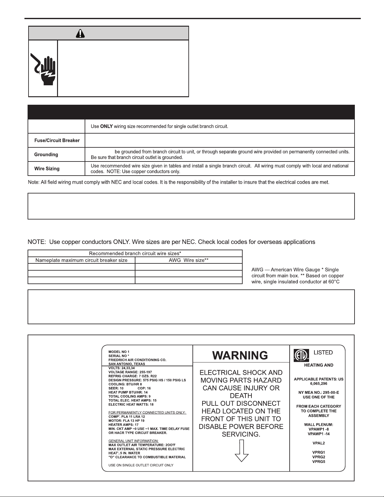
ELECTRICAL REQUIREMENTS
Wire Size
Unit MUST
Sample Nameplate
120524
COOLING EQUIPMENT
FOLLOWING ITEMS
OUTDOOR GRILLE
INDOOR GRILLE
SAMPLE
Electrical Rating Tables
41A51
21A02
01A03
All units must be hard wired with properly sized breaker. See nameplate for specific chassis electrical requirements.
Supply voltage
See Electrical Rating Table below for wire size. Use HACR type breakers to avoid nuisance trips. All field wiring must be done
in accordance with NEC and local codes.
ELECTRIC SHOCK HAZARD
WARNING
Turn off electric power before service or installation. All electrical connnections and wiring
MUST be installed by a qualified electrician and
conform to the National Electrical Code and all
local codes which have jurisdiction. Failure to
do so can result in personal injury and/or death.
Supply voltage to the unit should be a nominal 208/230 volts. It must be between 197 volts and 253 volts. Supply voltage to
the unit should be checked WITH THE UNIT IN OPERATION. Voltage readings outside the specified range can be expected
to cause operating problems. Their cause MUST be investigated and corrected.
“Use ONLY time delayed fused disconnect or HACR type circuit breaker as indicated on the unit’s rating plate (see
sample on this page). Proper current protection to the unit is the responsibility of the owner”.
8
Page 11
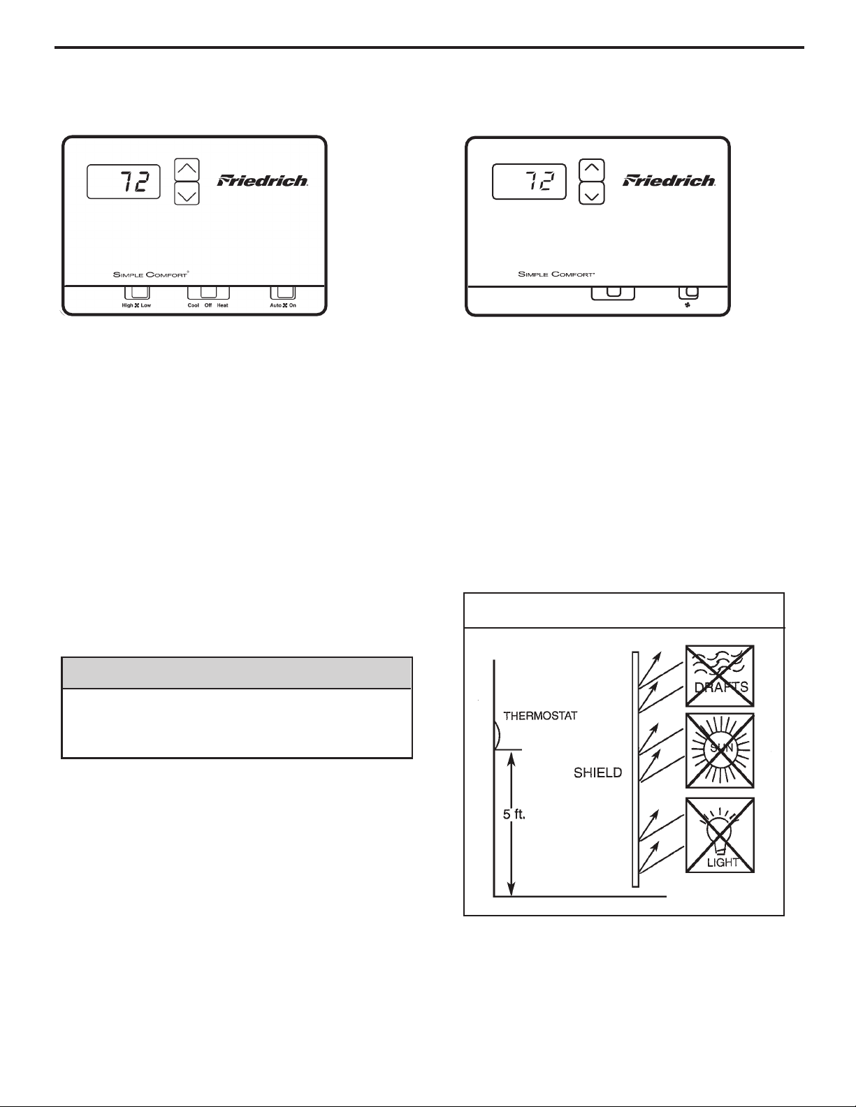
REMOTE THERMOSTAT AND LOW VOLTAGE CONTROL
Remote Thermostat
To control the unit with a wall-mounted thermostat:
1) Pull the disconnect switch.
2) Unscrew and remove the control box panel.
3) After selecting which side you want to run your thermostat
wire through, run the wires through the side hole in the box
to reach the connection terminal for the wiring.
4) Make the wire connections, appropriately matching the
wires as shown in the wiring diagram.
5) Once each wire is matched and connected, the unit is now
controlled by the thermostat.
6) Reattach the control box cover.
RT5 (Two speed fan) RT4 (One speed fan)
Cool Off Heat
Auto On
All Friedrich Vert-I-Pak units are factory configured to be
controlled by using a 24V single stage remote wall mounted
thermostat. The thermostat may be auto or manual changeover
as long as the control configuration matches that of the
Vert-I-Pak unit.
NOTE: An improperly operating, or poorly located room
thermostat can be the source of perceived equipment
problems. A careful check of the thermostat and wiring
must be made then to insure that it is not the source of
problems.
Manual Changeover Thermostat
For Heat Pump equipped units: a single stage, heat/cool
thermostat with a terminal for a reversing valve operation is
required. Terminal “B” should be continuously energized in the
heat mode and terminal “G” should be energized whenever
there is a call for heating or cooling. (Typically, a single stage,
heat/cool thermostat designed for use with electric heat
systems will meet the above requirements).
Location
The thermostat should not be mounted where it may be
affected by drafts, discharge air from registers (hot or cold),
or heat radiated from the sun or appliances.
The thermostat should be located about 5 Ft. above the
fl oor in an area of average temperature, with good air
circulation. Close proximity to the return air grille is the
best choice.
Mercury bulb type thermostats MUST be level to control
temperature accurately to the desired set-point. Electronic
digital type thermostats SHOULD be level for aesthetics.
Thermostat Location
NOTICE
DO NOT use a two (2) stage Heat Pump Thermostat.
Use of this type of thermostat may result in equipment
and/or property damage
CONNECTIONS
9
Page 12
REMOTE THERMOSTAT AND LOW VOLTAGE CONTROL
Desk Control Terminals
The Friedrich VERT-I-PAK has built-in provisions for
connection to an external switch to control power to the unit.
The switch can be a central desk control system or even a
normally open door switch.
For desk control operation, connect one side of the switch to
the D1 terminal and the other to the D2 terminal. Whenever
the switch closes, the unit operation will stop.
Maximum Wire Length for Desk Control Switch
Wire Size Maximum Length
#24 400 ft.
#22 600 ft.
#20 900 ft.
#18 1500 ft.
#16 2000 ft.
Auxiliary Fan Control
The Smart Center also has the ability to control a 24VAC
relay to activate an auxiliary, or transfer, fan. The outputs
are listed as F1 and F2 on the control board.
To connect the relay, simply wire one side of the relay to
F1 and the other side to F2. Anytime that the fan runs, the
terminals will send a 24VAC signal to the relay. The relay
must be 24 VAC, 50mA or less.
Note: The relay and auxiliary fans must be field supplied.
Note: The desk
control system and
switches must be
field supplied.
Thermostat Connections
C = Common Ground
W = Call for Heating
Y = Call for Cooling
R = 24V Power from Unit
GL = Call for Fan (Low Speed)
GH = Call for Fan (High Speed)
B = Reversing Valve Energized in heating mode
*If only one G terminal is present on thermostat, connect
to GL for low fan or to GH for high fan operation.
NOTE: It is the installer’s responsibility to ensure that all
control wiring connections are made in accordance with
the Freidrich installation instructions. Questions concerning proper connections to the unit should be directed to
the factory: 210-357-4400.
CONNECTIONS (Continued)
10
Page 13
ELECTRONIC CONTROL BOARD FEATURES
The new Friedrich Vert-I-Pak has state of the art features to improve guest comfort and conserve energy. Through
the use of specically designed control software, Friedrich has accomplished what other Manufacturer’s have only
attempted – a quiet, dependable, affordable and easy to use Vert-I-Pak.
Below is a list of standard features on every Friedrich VPAK and their benet to the owner.
Quiet Start/Stop
Fan Delay
Remote Thermostat
Operation
Internal Diagnostic
Program
Service Error Code
Storage
Room Freeze
Protection
Random
Compressor Restart
Digital Defrost
Thermostat
The fan start and stop delays prevent abrupt changes in room acoustics due to the compressor energizing
or stopping immediately. Upon call for cooling or heating the unit fan will run for ve seconds prior to energizing the compressor. Also, the fan off delay allows for “free cooling” by utilizing the already cool indoor
coil to its maximum capacity by running for 30 seconds after the compressor.
VPAK units are thermostat controlled.
The new Friedrich digital VPAK features a self diagnostic program that can alert maintenance to compo-
nent failures or operating problems. The internal diagnostic program saves properties valuable time when
diagnosing running problems.
The self diagnosis program will also store error codes in memory if certain conditions occur and correct
themselves such as extreme high or low operating conditions or activation of the room freeze protection
feature. Storing error codes can help properties determine if the unit faced obscure conditions or if an error
occurred and corrected itself.
When the VPAK senses that the indoor room temperature has fallen to 40°F the unit will cycle on high fan
and the electric strip heat to raise the room temperature to 46°F then cycle off again. This feature works
regardless of the mode selected and can be turned off. The control will also store the Room Freeze cycle
in the service code memory for retrieval at a later date. This feature ensures that unoccupied rooms do not
reach freezing levels where damage can occur to plumbing and xtures.
Multiple compressors starting at once can often cause electrical overloads and premature unit failure.
The random restart delay eliminates multiple units from starting at once following a power outage or initial
power up. The compressor delay will range from 180 to 240 seconds.
The new Friedrich VPAK uses a digital thermostat to accurately monitor the outdoor coil conditions to allow
the heat pump to run whenever conditions are correct. Running the VPAK in heat pump mode save energy
and reduces operating costs. The digital thermostat allows maximization of heat pump run time.
Instant Heat
Heat Pump Mode
Emergency Heat
Override
Desk Control Ready
Indoor Coil Frost
Sensor
Ultra-Quiet Air
System
High Efciency
Rotary Compressor
Auxiliary Fan Ready
Heat pump models will automatically run the electric heater during compressor lock-out to quickly provide
heat when initially energized, then return to heat pump mode. This ensures that the room is heated quickly
without the usual delay associated with heat pump units.
In the event of a compressor failure in heat pump mode the compressor may be locked out to provide heat
through the resistance heater. This feature ensures that even in the unlikely event of a compressor failure
the room temperature can be maintained until the compressor can be serviced.
All electronic VPAK units have low voltage terminals ready to connect a desk control energy management
system. Controlling the unit from a remote location like the front desk can reduce energy usage and
requires no additional accessories at the VPAK.
The frost sensor protects the compressor from damage in the event that air ow is reduced or low outdoor
temperatures cause the indoor coil to freeze. When the indoor coil reaches 30
diabled and the fan continues to operate based on demand. Once the coil temperature returns to 45°F the
compressor returns to operation.
The VPAK series units feature a indoor fan system design that reduces sound levels without
lowering airow and preventing proper air circulation.
The VPAK benets quality components and extensive development to ensure a quiet, efcient and
dependable unit.
High efciency rotary compressors are used on all Friedrich VPAKs to maximize durability and efciency.
The VPAK features a 24V AC terminal for connection to an auxiliary fan that may be used to transfer air to
adjoining rooms. Auxiliary fans can provide conditioning to multiple rooms.
°F the compressor is
11
Page 14
Low fan
High fan
Fan only
Power
Temp
Temp
Cool
Heat
1 2 3 4 5 6 7 8
O
N
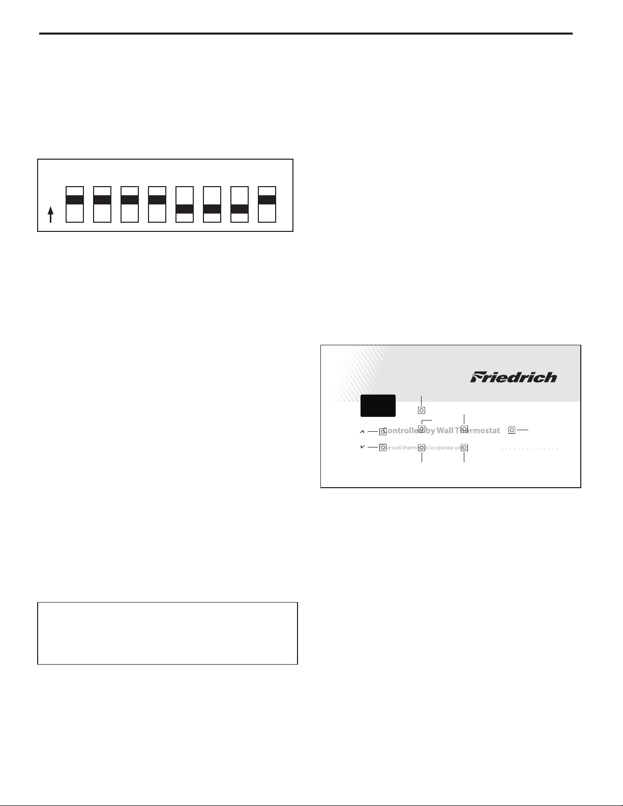
Electronic Control Configuration
The adjustable control dip switches are located at the lower
left hand portion of the digital Smart Center. The inputs are
only visible and accessible with the front cover removed from
the Unit.
Factory Dip Switch Configuration
Dip Switch Setting
Switches 1-4 ON
Switch 5-7 OFF
Switch 8 ON
Room Freeze Protection – Switch 6
Units are shipped from the factory with the room freeze protection disabled. Room Freeze Protection can be switched on at
the owner’s preference by moving Dip Switch 6 to ‘ON’. This
feature will monitor the indoor room conditions and in the event
that the room falls below 40°F the unit will cycle on high fan with
the electric heater. This occurs regardless of mode.
Emergency Heat Override – Switch 7
Units are shipped from the factory with the room emergency
heat override disabled. In the unlikely event of a compressor
failure a heat pump unit may be switched to operate in only the
electric heat mode until repairs can be made, by moving Dip
Switch 7 to ‘ON’.
Discharge Air Sensor Override – Switch 8
This switch MUST remain in the “ON” position for Vert-I-Pak
models, since they do not use a discharge air sensor. If the
switch is positioned in the “OFF” position on these models it
will result in the erroneous display Error Code 14 indicating that
the Discharge air temperature sensor is open or shorted.
Note: In order for the control to recognize “Dip” switch
setting changes, the unit must be disconnected
from power supply when making any configuration
changes.
Error Code Diagnostics
The VPAK electronic control continuously monitors the Vert-I-Pak
unit operation and will store error codes if certain conditions
are witnessed. In some cases the unit may take action and shut
the unit off until conditions are corrected.
To access the error code menu press the ‘HEAT’ and ‘HIGH
FAN’ buttons simultaneously for three seconds. If error codes
are present they will be displayed. If multiple codes exist you
can toggle between error codes using the temp up ▲ button. To
clear all codes press the temp down ▼ button for three seconds
while in the error code mode. To exit without losing codes
press the ‘Low Fan’ button.
Button Location for Vert-I-Pak Models
With the remote thermostat escutcheon installed, the button
locations to access the diagnostics mode can be located as
shown below.
Electronic Control Error Code
Diagnostics and Test Mode
* Heat and high fan - access error codes
* Temp up ▲ and temp down ▼ - toggle between error codes
* Low fan - exit error code mode without losing stored error
codes.
* Temp down ▼ - clears all error codes
NOTE: Hold buttons down for three seconds.
12
Page 15

Electronic Control Error Code Diagnostics
Error
Code
esuaC elbissoPtinU yB nekaT noitcAnoitalsnarT edoC
yllamroN gnitarepO tinUenoNeerF rorrEFE
02
Extreme low voltage condition exists (<198V
for 230V units and <239V for 265V units).
Shut unit down. Flash error code. When
voltage rises to adequate level normal unit
operation is restored.
• Inadequate power supply
• Defective breaker
• Blown fuse
03
Return air thermistor sensor open or
short circuit
Leave unit running. Alternately flash error
code and set point.
• Defective sensor
04
Indoor coil thermistor sensor open or
short circuit
Leave unit running. Alternately flash
error code and set point.
05
Outdoor coil thermistor sensor open
or short circuit
Leave unit running. Switch to Electric Heat
Mode (Heat Pump only). Alternately flash
error code and set point.
• Defective sensor
06
Outdoor coil Temperature > 175° F for
2 consecutive minutes. (Heat Pump
models only)
Shut unit down for 5 minutes, Alternately
flash error code and set point, then try again
2 times, if unit fails the 3rd time then shut
unit down and alternately flash error code
and set point.
• Dirty coil
• Fan motor failure
• Restricted air flow
07
Indoor coil temperature <30° F for 2
consecutive minutes.
Shut down Compressor, and continue fan
operation. Alternately flash error code and
set point until the indoor coil thermistor
reaches 45° F. Then, (after lockout time of
180 to 240 seconds expires), re-energize
the compressor .
• Dirty filters
• Dirty coil
• Fan motor failure
• Restricted air flow
• Improper refrigerant charge
• Restriction in refrigerant circuit
08
Unit cycles (Heat or Cool demand) >
9 times per hour
Leave unit running. Store error code in
memory.
• Unit oversized
• Low load conditions
09
Unit cycles (Heat or Cool demand) <
3 times per hour
Leave unit running. Store Error Code in
memory.
• Unit undersized
• High load conditions
10 Room Freeze Protection triggered
Leave unit running. Alternately flash error
F°04 woleb llef erutarepmet mooR •.tniop tes dna edoc
11 No Signal to “GL or “GH” terminal Shut unit down. Flash error code.
• Defective remote thermostat
• Defective thermostat wiring
13
High Pressure switch open (24K BTU Only)
Jumper wire loose/missing (9-18K BTU)
Shut unit down. Flash error code.
• Dirty coil
• Fan motor failure
• Restricted air flow
• Non-condensables in refrigeration system
• Non-condensables in refrigeration system
14
Discharge air temperature sensor open or
shorted
Leave unit running. Alternately flash error
code and set point.
• Dip switch # 8 set to "OFF" position
Diagnostics
The Ele ctron ic co ntrol c ontin uousl y monitors t he VPAK unit operation and will store service codes if certain
conditions are witnessed. In some cases the unit may take action and shut the unit off until conditions are corrected.
To access the error code menu press the ‘Heat’ and ‘High Fan’ buttons simultaneously for three seconds. If
error codes are present they will be displayed. If multiple codes exist you can toggle between messages using the
temp up button. To clear all codes press the temp down button for three seconds while in the error code mode. To
exit without changing codes press the ‘Low Fan’ button.
Test Mode
For service and diagnostic use only, the built-in timers and delays on the VPAK may be bypassed by pressing the ‘Cool’ and
‘Low Fan’ buttons simultaneously for three seconds while in any mode to enter the test mode. CE will be displayed when en-
tering test mode, and oE will be displayed when exiting. The test mode will automatically be exited 30 minutes after entering it
or by pressing the ‘Cool’ and ‘Low Fan’ buttons simultaneously for three seconds.
Note: To access the Test Mode while under remote wall thermostat operation, remove thermostat’s wires at the
terminal block on the electronic control board then connect a jumper wire between GL and GH.
13
Page 16

VPAK ELECTRONIC CONTROL FEATURES
Thermostat Compatibility:
The VPAK Electronic Control is compatible with
Friedrich RT4 and RT5 Thermostats.
The VPAK Electronic control is also compatible
with most standard Single Stage Heat/Cool
Thermostats.
NOTE: Field supplied Thermostats MUST
energize the fan circuit on a call for Heating
or Cooling, and (when used with a Heat
Pump Unit) MUST energize the “B” terminal
in Heating in order for the unit to function
correctly.
Compressor Time Delay:
The Electronic control is equipped with a
random (180 to 240 seconds) Compressor
time delay that is initiated every time the
compressor cycles “Off.” The “delay on break”
timer is initiated by the following actions:
(1) Satisfying the temperature set point
(2) Changing mode to fan only
(3) Turning the unit off
(4) Restoring power after a failure
Note: The Compressor Time Delay feature is
disabled during “Test Mode” operation.
Fan delay:
The Electronic Control is equipped with a
feature that will start the fan 5 seconds EARLY
(i.e. before compressor or heater) when unit
cycles “ON.” When the unit cycles “OFF” the
fan will DELAY for 30 seconds in Cooling and
15 seconds in Heating.
Note: the fan delay is disabled during Test
Mode operation.
Emergency Heat:
The Electronic Control is equipped with a
feature that allows servicer/end user to switch
to electric heat operation when the compressor
fails during the heating season, (See DIP
switch position 7) until the compressor can be
replaced.
14
Page 17

EXAMPLE: Airfl ow requirements are calculated as follows:
(Having a wet coil creates additional resistance to airfl ow.
This addit ional resistance must be taken into consideration
to obtain accurate airfl ow information.
External Static Pressure
External Static Pressure can best be defi ned as the pressure
difference (drop) between the Positive Pressure (discharge)
and the Negative Pressure (intake) sides of the blower.
External Static Pressure is developed by the blower as a
result of resistance to airfl ow (Friction) in the air distribution
system EXTERNAL to the VERT-I-PAK cabinet.
Resistance applied externally to the VERT-I-PAK (i.e. duct
work, fi lters, etc.) on either the supply or return side of the
External Static Pressure is affected by two (2) factors.
1. Resistance to Airfl ow as already explained.
2. Blower Speed. Changing to a higher or lower blower
speed will raise or lower the External Static Pressure
accordingly.
These affects must be understood and taken into consideration
when checking External Static Pressure/Airfl ow to insure that
the system is operating within design conditions.
Operating a system with insuffi cient or excessive airfl ow
can cause a variety of different operating problems.
Among these are reduced capacity, freezing evaporator
coils, premature compressor and/or heating component
failures. etc.
System airfl ow should always be verifi ed upon completion
of a new installation, or before a change-out, compressor
replacement, or in the case of heat strip failure to insure
that the failure was not caused by improper airfl ow.
Checking External Static Pressure
The airflow through the unit can be determined by
measuring the external static pressure of the system, and
consulting the blower performance data for the specifi c
VERT-I-PAK.
1. Set up to measure external static pressure at the
supply and return air.
2. Ensure the coil and fi lter are clean, and that all the
registers are open.
3. Determine the external static pressure with the
blower operating.
4. Refer to the
Air Flow Data for your VERT-I-PAK
system to fi nd the actual airfl ow for factory-selected
fan speeds.
5. If the actual airfl ow is either too high or too low, the
blower speed will need to be changed to appropriate
setting or the ductwork will need to be reassessed
and corrections made as required.
6. Select a speed, which most closely provides the
required airfl ow for the system.
7. Recheck the external static pressure with the
new speed. External static pressure (and actual
airfl ow) will have changed to a higher or lower value
depending upon speed selected. Recheck the actual
airfl ow (at this "new" static pressure) to confi rm
speed selection.
8. Repeat steps 8
and 9 (if necessary) until proper
airfl ow has been obtained.
system causes an INCREASE in External Static Pressure accompanied by a REDUCTION in airfl ow.
Determining the Indoor CFM: Chart A – CFM
Model
VEA12/VHA12 VEA18/VHA18VEA09/VHA09
ESP (")
.00"
.10"
.20"
.30”
Low
340
300
230
140
High
385
340
280
190
Low
420
350 *
290
250
High
470
420 **
350
300
Low
430
400
340
290
High
480
450
400
330
Highlighted values indicate rated performance point.
Rated performance for
* VEA12
Rated Performance for
** VHA12
ESP (") Low High
.00" 690 740
.10" 610 700
.20" 560 640
.30" 510 580
.40" 450 520
Model
VEA24/VHA24
Highlighted values indicate rated performance point.
15
Page 18

The Vert-I-Pak A series units must be installed with a free
return air configuration. The table below lists the indoor
airflow at corresponding static pressures. All units are rarted
at low speed.
The Vert-I-Pak units are designed for either single speed or
two fan speed operation. For single speed operation refer to
the airflow table below and select the most appropriate CFM
based on the ESP level. Connect the fan output from the
thermostat to the unit on either the GL terminal for low speed
or to the GH terminal for high speed operation.
For thermostats with two-speed fan outputs connect the low
speed output to the unit GL terminal and the high speed
output to the GH terminal.
Ductwork Preparation
Indoor Airflow Data
Fresh Air Door
If flex duct is used, be sure all the slack is pulled out of the
flex duct. Flex duct ESP can increase considerably when
not fully extended. DO NOT EXCEED a total of .30 ESP, as
this is the MAXIMUM design limit for the VERT-I-PAK
A-Series unit.
The Fresh Air Door is an “intake” system. The fresh air door
opened via a slide on the front of the chassis located just
above the indoor coil. Move the slide left to open and right
to close the fresh air door. The system is capable of up to 60
CFM of fresh air @ ~.3” H20 internal static pressure.
IMPORTANT: FLEX DUCT CAN COLLAPSE AND
CAUSE AIRFLOW RESTRICTIONS. DO NOT
USE FLEX DUCT FOR: 90 DEGREE BENDS, OR
UNSUPPORTED RUNS OF 5 FT. OR MORE.
EXAMPLE: Measured voltage to unit (heaters) is 230 volts.
Measured Current Draw of strip heaters is 11.0 amps.
230 x 11.0 = 2530
2530/1000 = 2.53 Kilowatts
2.53 x 3413 = 8635
Supply Air 95°F
Return Air 75°F
Temperature Rise 20
°
20 x 1.08 = 21.6
8635
= 400 CFM
21.6
1 ½ TON SYSTEM ( 18,000 Btu)
Operating on high speed @ 230 volts with dry coil
measured external static pressure .10
Air Flow = 450 CFM
In the same SYSTEM used in the previous example but
having a WET coil you must use a correction factor of
.95 (i.e. 450 x .95=428 CFM) to allow for the resistance
(internal) of the condensate on the coil.
It is important to use the proper procedure to check
external
Static Pressure and determine actual air fl ow. Since in
the case of the VERT-I-PAK, the condensate will cause
a reduction in measured External Static Pressure for the
given airfl ow.
It is also important to remember that when dealing with
VERT-l-PAK units that the measured External Static
Pressure increases as the resistance is added externally
to the cabinet. Example: duct work, fi lters, grilles.
Checking Approximate Airfl ow
If an inclined manometer or Magnehelic gauge is not
available to check the External Static Pressure, or the
blower performance data is unavailable for your unit,
approximate air fl ow call be calculated by measuring the
temperature rise, then using tile following criteria.
KILOWATTS x 3413
= CFM
Temp Rise x 1.08
Electric Heat Strips
The approximate CFM actually being delivered can be
calculated by using the following formula:
DO NOT simply use the Kilowatt Rating of the heater (i.e.
2.5, 3.4, 5.0) as this will result in a less-than-correct airfl ow
calculation. Kilowatts may be calculated by multiplying
the measured voltage to the unit (heater) times the
measured current draw of all heaters (ONLY) in operation
to obtain watts. Kilowatts are than obtained by dividing
by 1000.
Explanation of charts
Chart A is the nominal dry coil VERT-I-PAK CFMs. Chart
B is the correction factors beyond nominal conditions.
Correct CFM (if needed):
Chart B – Correction Multipli
ers
16
Page 19

BLOWER / FAN MOTOR TEST
BLOWER / FAN MOTOR
A single phase permanent split capacitor motor is used to drive
the evaporator blower and condenser fan. A self-resetting
overload is located inside the motor to protect against high
temperature and high amperage conditions.
ELECTRIC SHOCK HAZARD
WARNING
Disconnect power to the unit before
servicing. Failure to follow this warning
could result in serious injury or death.
1. Visually inspect the motor’s wiring, housing etc., and
determine that the capacitor is serviceable.
2. Make sure the motor has cooled down.
3. Disconnect the fan motor wires from the control board.
4. Test for continuity between the windings also, test to
ground.
5. If any winding is open or grounded replace the motor.
COMPONENTS TESTING
Many motor capacitors are internally fused. Shorting the
terminals will blow the fuse, ruining the capacitor. A 20,000
ohm 2 watt resistor can be used to discharge capacitors
safely. Remove wires from capacitor and place resistor
across terminals. When checking a dual capacitor with
a capacitor analyzer or ohmmeter, both sides must be
tested.
Capacitor Check with Capacitor Analyzer
The capacitor analyzer will show whether the capacitor
is “open” or “shorted.” It will tell whether the capacitor
is within its micro farads rating and it will show whether
the capacitor is operating at the proper power-factor
percentage. The instrument will automatically discharge
the capacitor when the test switch is released.
Capacitor Connections
The starting winding of a motor can be damaged by a
shorted and grounded running capacitor. This damage
usually can be avoided by proper connection of the running
capacitor terminals.
CAPACITORS
From the supply line on a typical 230 volt circuit, a 115 volt
potential exists from the “R” terminal to ground through a
possible short in the capacitor. However, from the “S” or start
terminal, a much higher potential, possibly as high as 400
volts, exists because of the counter EMF generated in the
start winding. Therefore, the possibility of capacitor failure
is much greater when the identied terminal is connected
to the “S” or start terminal. The identied terminal should
always be connected to the supply line, or “R” terminal,
never to the “S” terminal.
When connected properly, a shorted or grounded running
capacitor will result in a direct short to ground from the “R”
terminal and will blow the line fuse. The motor protector
will protect the main winding from excessive temperature.
WARNING
ELECTRIC SHOCK HAZARD
Turn off electric power before servicing.
Discharge capacitor with a 20,000 Ohm 2 Watt
resistor before handling.
Failure to do so may result in personal injury,
or death.
17
Page 20

COMPONENTS TESTING (Continued)
HEATER ELEMENTS AND LIMIT SWITCHES’
SPECIFICATIONS
All heat pumps and electric heat models are equipped
with a heating element and a limit switch (bimetal thermostat). The limit is in series with the element and will
interrupt the power at a designed temperature.
Should the blower motor fail, lter become clogged or airow be restricted etc., the high limit switch will open and
interrupt the power to the heater before reaching an unsafe temperature condition.
TESTING THE HEATING ELEMENTS AND
LIMIT SWITCHES
WARNING
ELECTRIC SHOCK HAZARD
Disconnect power to the unit before
servicing. Failure to follow this warning
could result in serious injury or death.
Testing of the heating elements can be made with an
ohmmeter or continuity tester across the terminals after
the power wires have been removed. Test the limit switch
for continuity across its input and output terminals.Test
below the limit switch’s reset temperature.
DRAIN PAN VALVE
During the cooling mode of operation, condensate which
collects in the drain pan is picked up by the condenser fan
blade and sprayed onto the condenser coil. This assists
in cooling the refrigerant plus evaporating the water.
During the heating mode of operation, it is necessary that
water be removed to prevent it from freezing during cold
outside temperatures. This could cause the condenser
fan blade to freeze in the accumulated water and prevent
it from turning.
To provide a means of draining this water, a bellows type
drain valve is installed over a drain opening in the base
pan.
This valve is temperature sensitive and will open when
the outside temperature reaches 40°F. The valve will
close gradually as the temperature rises above 40°F to
fully close at 60°F.
Bellows Assembly
Drain Pan Valve
18
Page 21

REFRIGERATION SEQUENCE OF OPERATION
1. Compressor
2. Evaporator Coil Assembly
3. Condenser Coil Assembly
4. Capillary Tube
5. Compressor Overload
Refrigeration Assembly
A good understanding of the basic operation of the
refrigeration system is essential for the service technician.
Without this understanding, accurate troubleshooting of
refrigeration system problems will be more difcult and time
consuming, if not (in some cases) entirely impossible. The
refrigeration system uses four basic principles (laws) in its
operation they are as follows:
1. “Heat always ows from a warmer body to a cooler
body.”
2. “Heat must be added to or removed from a substance
before a change in state can occur”
3. “Flow is always from a higher pressure area to a lower
pressure area.”
4. “The temperature at which a liquid or gas changes state
is dependent upon the pressure.”
The refrigeration cycle begins at the compressor. Starting
the compressor creates a low pressure in the suction line
which draws refrigerant gas (vapor) into the compressor.
The compressor then “compresses” this refrigerant, raising
its pressure and its (heat intensity) temperature.
The refrigerant leaves the compressor through the discharge
Line as a hot High pressure gas (vapor). The refrigerant
enters the condenser coil where it gives up some of its
heat. The condenser fan moving air across the coil’s nned
surface facilitates the transfer of heat from the refrigerant to
the relatively cooler outdoor air.
When a sufcient quantity of heat has been removed from
the refrigerant gas (vapor), the refrigerant will “condense”
(i.e. change to a liquid). Once the refrigerant has been
condensed (changed) to a liquid it is cooled even further by
the air that continues to ow across the condenser coil.
The VPAK design determines at exactly what point (in
the condenser) the change of state (i.e. gas to a liquid)
takes place. In all cases, however, the refrigerant must be
totally condensed (changed) to a Liquid before leaving the
condenser coil.
The refrigerant leaves the condenser Coil through the liquid
line as a warm high pressure liquid. It next will pass through
the refrigerant drier (if so equipped). It is the function of the
drier to trap any moisture present in the system, contaminants,
and large particulate matter.
The liquid refrigerant next enters the metering device. The
metering device is a capillary tube. The purpose of the
metering device is to “meter” (i.e. control or measure) the
quantity of refrigerant entering the evaporator coil.
In the case of the capillary tube this is accomplished (by
design) through size (and length) of device, and the pressure
difference present across the device.
Since the evaporator coil is under a lower pressure (due to
the suction created by the compressor) than the liquid line,
the liquid refrigerant leaves the metering device entering the
evaporator coil. As it enters the evaporator coil, the larger
area and lower pressure allows the refrigerant to expand
and lower its temperature (heat intensity). This expansion is
often referred to as “boiling”. Since the unit’s blower is moving
indoor air across the nned surface of the evaporator coil,
the expanding refrigerant absorbs some of that heat. This
results in a lowering of the indoor air temperature, hence the
“cooling” effect.
The expansion and absorbing of heat cause the liquid
refrigerant to evaporate (i.e. change to a gas). Once the
refrigerant has been evaporated (changed to a gas), it is
heated even further by the air that continues to ow across
the evaporator coil.
The particular system design determines at exactly what
point (in the evaporator) the change of state (i.e. liquid to a
gas) takes place. In all cases, however, the refrigerant must
be totally evaporated (changed) to a gas before leaving the
evaporator coil.
The low pressure (suction) created by the compressor
causes the refrigerant to leave the evaporator through the
suction line as a cool low pressure vapor. The refrigerant then
returns to the compressor, where the cycle is repeated.
19
Page 22

SERVICE
Servicing / Chassis Quick Changeouts
.
Warranty
To Remove the Chassis from the Closet:
B. Switch the wall Thermostat off.
C. Pull the Power Disconnect located in the front of the chassis.
A. Disconnect the power coming into the unit from the main
breaker panel or the closet mounted disconnect.
D. Disconnect the electrical connection.
E. Disconnect the duct work.
G. Slide the chassis out of the wall plenum.
F. Disconnect condensate drain on 9-18,000 BTU models.
H. Lift the chassis out of the utility closet.
ELECTRIC SHOCK HAZARD
Turn off electric power before service or
installation.
Extreme care must be used, if it becomes
necessary to work on equipment with power
applied.
Failure to do so could result in serious injury or
death.
Be careful with the sharp edges and corners.
Wear protective clothing and gloves, etc.
Failure to do so could result in minor to
moderate injury.
WARNING
CAUTION
CUT/SEVER HAZARD
20
Page 23

SEALED REFRIGERATION SYSTEM REPAIRS
IMPORTANT
ANY SEALED SYSTEM REPAIRS TO COOL-ONLY MODELS REQUIRE THE INSTALLATION OF A LIQUID LINE DRIER.
ALSO, ANY SEALED SYSTEM REPAIRS TO HEAT PUMP MODELS REQUIRE THE INSTALLATION OF A SUCTION LINE DRIER.
EQUIPMENT REQUIRED:
1. Voltmeter
2. Ammeter
3. Ohmmeter
9. High Pressure Gauge - (0 - 750 lbs.)
10. Low Pressure Gauge - (30 - 200 lbs.)
11. Vacuum Gauge - (0 - 1000 microns)
4. E.P.A. Approved Refrigerant Recovery System
5. Vacuum Pump (capable of 200 microns or less
vacuum.)
6. Acetylene Welder
7. Electronic Halogen Leak Detector capable of detecting HFC (Hydrouorocarbon) refrigerants.
8. Accurate refrigerant charge measuring device such
as:
a. Balance Scales - 1/2 oz. accuracy
b. Charging Board - 1/2 oz. accuracy
WARNING
RISK OF ELECTRIC SHOCK
Unplug and/or disconnect all electrical power
to the unit before performing inspections,
maintenances or service.
Failure to do so could result in electric shock,
serious injury or death.
WARNING
HIGH PRESSURE HAZARD
Sealed Refrigeration System contains refrigerant
and oil under high pressure.
12. Facilities for owing nitrogen through refrigeration tubing
during all brazing processes.
EQUIPMENT MUST BE CAPABLE OF:
1. Recovering refrigerant to EPA required levels.
2. Evacuation from both the high side and low side of the
system simultaneously.
3. Introducing refrigerant charge into high side of the
system.
4. Accurately weighing the refrigerant charge actually
introduced into the system.
Too much refrigerant (overcharge) in the system is just as bad
(if not worse) than not enough refrigerant (undercharge). They
both can be the source of certain compressor failures if they
remain uncorrected for any period of time. Quite often, other
problems (such as low air ow across evaporator, etc.) are
misdiagnosed as refrigerant charge problems. The refrigerant
circuit diagnosis chart will assist you in properly diagnosing
these systems.
An overcharged unit will at times return liquid refrigerant
(slugging) back to the suction side of the compressor eventually
causing a mechanical failure within the compressor. This
mechanical failure can manifest itself as valve failure, bearing
failure, and/or other mechanical failure. The specic type of
failure will be inuenced by the amount of liquid being returned,
and the length of time the slugging continues.
Proper safety procedures must be followed,
and proper protective clothing must be worn
when working with refrigerants.
Failure to follow these procedures could
result in serious injury or death.
Refrigerant Charging
Proper refrigerant charge is essential to proper unit operation. Operating a unit with an improper refrigerant charge will
result in reduced performance (capacity) and/or efciency.
Accordingly, the use of proper charging methods during servicing will insure that the unit is functioning as designed and
that its compressor will not be damaged.
Not enough refrigerant (undercharge) on the other hand, will
cause the temperature of the suction gas to increase to the point
where it does not provide sufcient cooling for the compressor
motor. When this occurs, the motor winding temperature will
increase causing the motor to overheat and possibly cycle open
the compressor overload protector. Continued overheating of
the motor windings and/or cycling of the overload will eventually
lead to compressor motor or overload failure.
21
Page 24

Method Of Charging / Repairs
The acceptable method for charging the RAC system is the
Weighed in Charge Method. The weighed in charge method is
applicable to all units. It is the preferred method to use, as it is
the most accurate.
The weighed in method should always be used whenever
a charge is removed from a unit such as for a leak repair,
compressor replacement, or when there is no refrigerant
charge left in the unit. To charge by this method, requires the
following steps:
1. Install a piercing valve to remove refrigerant from the
sealedsystem. (Piercing valve must be removed from the
system before recharging.)
2. Recover Refrigerant in accordance with EPA regulations.
WARNING
BURN HAZARD
Proper safety procedures must be followed,
and proper protective clothing must be worn
when working with a torch.
Failure to follow these procedures could
result in moderate or serious injury.
3. Install a process tube to sealed system.
CAUTION
FREEZE HAZARD
Proper safety procedures must be followed,
and proper protective clothing must be worn
when working with liquid refrigerant.
Failure to follow these procedures could
result in minor to moderate injury.
4. Make necessary repairs to system.
5. Evacuate system to 200 microns or less.
6. Weigh in refrigerant with the property quantity of R-410A
refrigerant.
7. Start unit, and verify performance.
WARNING
BURN HAZARD
Proper safety procedures must be followed,
and proper protective clothing must be worn
when working with a torch.
Failure to follow these procedures could
result in moderate or serious injury.
8. Crimp the process tube and solder the end shut.
WARNING
ELECTRIC SHOCK HAZARD
Turn off electric power before service or
installation.
Extreme care must be used, if it becomes
necessary to work on equipment with power
applied.
Failure to do so could result in serious injury or
death.
WARNING
HIGH PRESSURE HAZARD
Sealed Refrigeration System contains refrigerant
and oil under high pressure.
Proper safety procedures must be followed,
and proper protective clothing must be worn
when working with refrigerants.
Failure to follow these procedures could
result in serious injury or death.
Undercharged Refrigerant Systems
An undercharged system will result in poor performance
(low pressures, etc.) in both the heating and cooling
cycle.
Whenever you service a unit with an undercharge of
refrigerant, always suspect a leak. The leak must be
repaired before charging the unit.
To check for an undercharged system, turn the unit on,
allow the compressor to run long enough to establish
working pressures in the system (15 to 20 minutes).
During the cooling cycle you can listen carefully at the exit
of the metering device into the evaporator; an intermittent
hissing and gurgling sound indicates a low refrigerant
charge. Intermittent frosting and thawing of the evaporator
is another indication of a low charge, however, frosting
and thawing can also be caused by insufcient air over
the evaporator.
Checks for an undercharged system can be made at
the compressor. If the compressor seems quieter than
normal, it is an indication of a low refrigerant charge.
A check of the amperage drawn by the compressor
motor should show a lower reading. (Check the Unit
Specication.)
22
Page 25
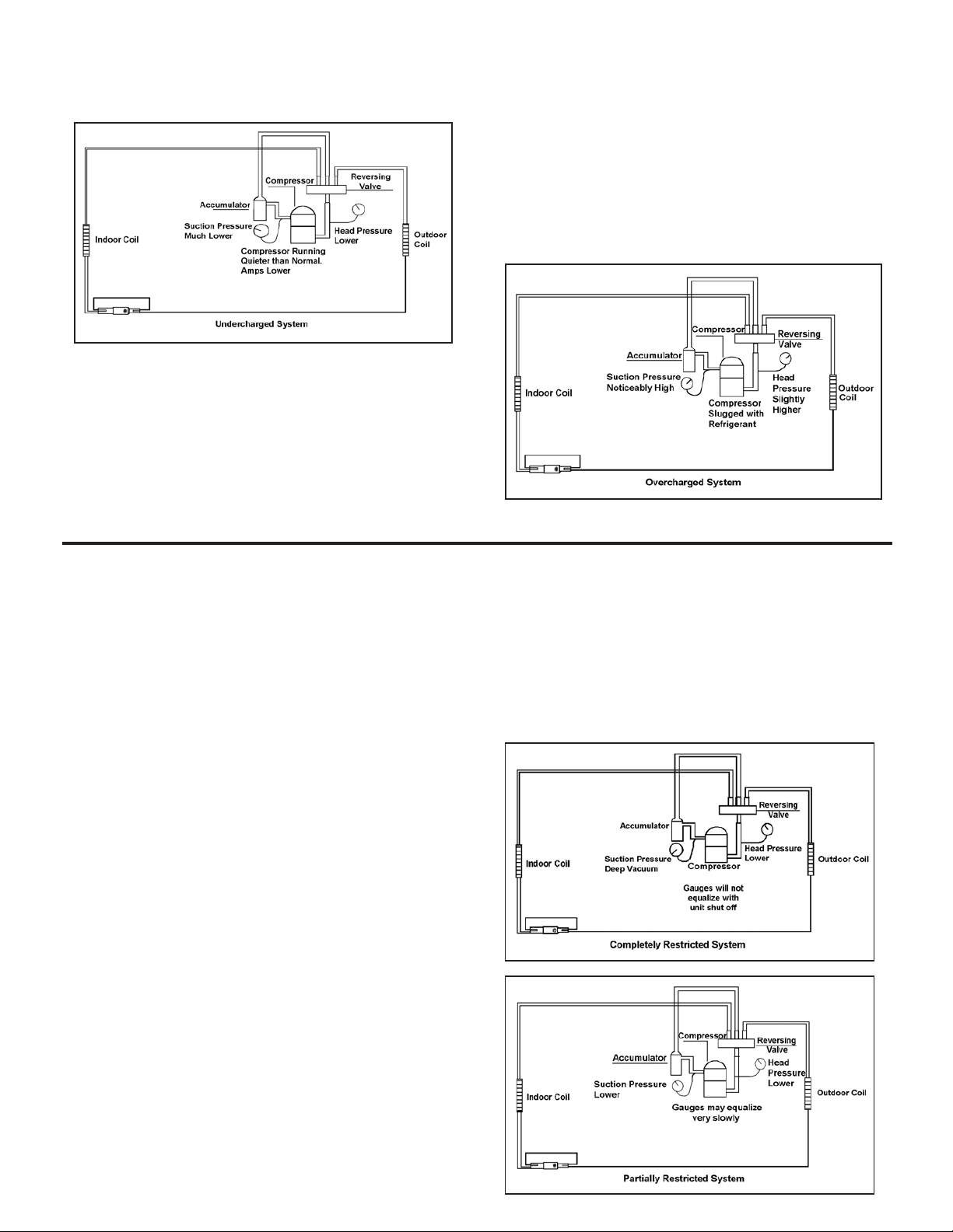
After the unit has run 10 to 15 minutes, check the gauge
pressures. Gauges connected to system with an undercharge
will have low head pressures and substantially low suction
pressures.
Overcharged Refrigerant Systems
Compressor amps will be near normal or higher.
Noncondensables can also cause these symptoms. To
conrm, remove some of the charge, if conditions improve,
system may be overcharged. If conditions don’t improve,
Noncondensables are indicated.
Whenever an overcharged system is indicated, always make
sure that the problem is not caused by air ow problems.
Improper air ow over the evaporator coil may indicate
some of the same symptoms as an over charged system.
An overcharge can cause the compressor to fail, since it
would be “slugged” with liquid refrigerant.
The charge for any system is critical. When the compressor
is noisy, suspect an overcharge, when you are sure that the
air quantity over the evaporator coil is correct. Icing of the
evaporator will not be encountered because the refrigerant
will boil later if at all. Gauges connected to system will usually
have higher head pressure (depending upon amount of over
charge). Suction pressure should be slightly higher.
Restricted Refrigerant System
Troubleshooting a restricted refrigerant system can be
difcult. The following procedures are the more common
problems and solutions to these problems. There are two
types of refrigerant restrictions: Partial restrictions and
complete restrictions.
A partial restriction allows some of the refrigerant to
circulate through the system.
With a complete restriction there is no circulation of
refrigerant in the system.
Restricted refrigerant systems display the same symptoms
as a “low-charge condition.”
When the unit is shut off, the gauges may equalize very
slowly.
Gauges connected to a completely restricted system will
run in a deep vacuum. When the unit is shut off, the gauges
will not equalize at all.
A quick check for either condition begins at the evaporator.
With a partial restriction, there may be gurgling sounds
at the metering device entrance to the evaporator. The
evaporator in a partial restriction could be partially frosted
or have an ice ball close to the entrance of the metering
device. Frost may continue on the suction line back to the
compressor.
Often a partial restriction of any type can be found by feel,
as there is a temperature difference from one side of the
restriction to the other.
With a complete restriction, there will be no sound at the
metering device entrance. An amperage check of the
compressor with a partial restriction may show normal
current when compared to the unit specication.
With a complete restriction the current drawn may be
considerably less than normal, as the compressor is
running in a deep vacuum (no load.) Much of the area of
the condenser will be relatively cool since most or all of the
liquid refrigerant will be stored there.
The following conditions are based primarily on a system
in the cooling mode.
23
Page 26

HERMETIC COMPONENTS CHECK
WARNING
BURN HAZARD
Proper safety procedures must be followed,
and proper protective clothing must be worn
when working with a torch.
Failure to follow these procedures could
result in moderate or serious injury.
METERING DEVICE
Capillary Tube Systems
WARNING
CUT/SEVER HAZARD
Be careful with the sharp edges and corners.
Wear protective clothing and gloves, etc.
Failure to do so could result in serious injury.
All units are equipped with capillary tube metering
devices.
Checking for restricted capillary tubes.
1. Connect pressure gauges to unit.
2. Start the unit in the cooling mode. If after a few minutes
of operation the pressures are normal, the check valve
and the cooling capillary are not restricted.
CHECK VALVE
A unique two-way check valve is used on the reverse cycle
heat pumps. It is pressure operated and used to direct the
ow of refrigerant through a single lter drier and to the
proper capillary tube during either the heating or cooling
cycle.
One-way Check Valve
(Heat Pump Models)
NOTE: The slide (check) inside the valve is made of teon.
Should it become necessary to replace the check valve,
place a wet cloth around the valve to prevent overheating
during the brazing operation.
CHECK VALVE OPERATION
In the cooling mode of operation, high pressure liquid enters
the check valve forcing the slide to close the opposite port
(liquid line) to the indoor coil. Refer to refrigerant ow chart.
This directs the refrigerant through the lter drier and cooling
capillary tube to the indoor coil.
In the heating mode of operation, high pressure refrigerant
enters the check valve from the opposite direction, closing
3. Switch the unit to the heating mode and observe the
gauge readings after a few minutes running time. If
the system pressure is lower than normal, the heating
capillary is restricted.
4. If the operating pressures are lower than normal in both
the heating and cooling mode, the cooling capillary is
restricted.
the port (liquid line) to the outdoor coil. The ow path of
the refrigerant is then through the lter drier and heating
capillary to the outdoor coil.
Failure of the slide in the check valve to seat properly in
either mode of operation will cause ooding of the cooling
coil. This is due to the refrigerant bypassing the heating or
cooling capillary tube and entering the liquid line.
COOLING MODE
In the cooling mode of operation, liquid refrigerant from
condenser (liquid line) enters the cooling check valve
forcing the heating check valve shut. The liquid refrigerant
is directed into the liquid dryer after which the refrigerant
is metered through cooling capillary tubes to evaporator.
(Note: liquid refrigerant will also be directed through the
heating capillary tubes in a continuous loop during the
cooling mode).
HEATING MODE
In the heating mode of operation, liquid refrigerant from
the indoor coil enters the heating check valve forcing the
cooling check valve shut. The liquid refrigerant is directed
into the liquid dryer after which the refrigerant is metered
through the heating capillary tubes to outdoor coils. (Note:
liquid refrigerant will also be directed through the cooling
capillary tubes in a continuous loop during the heating
mode).
24
Page 27
REVERSING VALVE DESCRIPTION/OPERATION
of the system. The pilot section of the valve opens and
WARNING
ELECTRIC SHOCK HAZARD
Disconnect power to the unit before servicing.
Failure to follow this warning could result in
serious injury or death.
The Reversing Valve controls the direction of refrigerant ow
to the indoor and outdoor coils. It consists of a pressure-
operated, main valve and a pilot valve actuated by a solenoid
plunger. The solenoid is energized during the heating cycle
only. The reversing valves used in the PTAC system is a
2-position, 4-way valve.
The single tube on one side of the main valve body is the
high-pressure inlet to the valve from the compressor. The
center tube on the opposite side is connected to the low
pressure (suction) side of the system. The other two are
connected to the indoor and outdoor coils. Small capillary
tubes connect each end of the main valve cylinder to the “A”
and “B” ports of the pilot valve. A third capillary is a common
return line from these ports to the suction tube on the main
valve body. Four-way reversing valves also have a capillary
tube from the compressor discharge tube to the pilot valve.
closes ports for the small capillary tubes to the main valve
to cause it to shift.
NOTE: System operating pressures must be near
normal before valve can shift.
The piston assembly in the main valve can only be shifted
by the pressure differential between the high and low sides
TESTING THE COIL
WARNING
ELECTRIC SHOCK HAZARD
Unplug and/or disconnect all electrical power
to the unit before performing inspections,
maintenances or service.
Failure to do so could result in electric shock,
serious injury or death.
The solenoid coil is an electromagnetic type coil mounted
on the reversing valve and is energized during the
operation of the compressor in the heating cycle.
1. Turn off high voltage electrical power to unit.
2. Unplug line voltage lead from reversing valve coil.
3. Check for electrical continuity through the coil. If you
do not have continuity replace the coil.
4. Check from each lead of coil to the copper liquid line
as it leaves the unit or the ground lug. There should
be no continuity between either of the coil leads
and ground; if there is, coil is grounded and must be
replaced.
5. If coil tests okay, reconnect the electrical leads.
6. Make sure coil has been assembled correctly.
NOTE: Do not start unit with solenoid coil removed from
valve, or do not remove coil after unit is in operation. This
will cause the coil to burn out.
CHECKING THE REVERSING VALVE
NOTE: You must have normal operating pressures before
the reversing valve can shift.
WARNING
HIGH PRESSURE HAZARD
Sealed Refrigeration System contains refrigerant
and oil under high pressure.
Proper safety procedures must be followed,
and proper protective clothing must be worn
when working with refrigerants.
Failure to follow these procedures could
result in serious injury or death.
Check the operation of the valve by starting the system
and switching the operation from “Cooling” to “Heating”
and then back to “Cooling”. Do not hammer on valve.
Occasionally, the reversing valve may stick in the heating
or cooling position or in the mid-position.
25
Page 28
When sluggish or stuck in the mid-position, part of the
discharge gas from the compressor is directed back to the
suction side, resulting in excessively high suction pressure.
Should the valve fail to shift from coooling to heating,
block the air ow through the outdoor coil and allow the
discharge pressure to build in the system. Then switch the
system from heating to cooling.
If the valve is stuck in the heating position, block the air
ow through the indoor coil and allow discharge pressure
to build in the system. Then switch the system from heating
to cooling.
Should the valve fail to shift in either position after increasing
the discharge pressure, replace the valve.
Dented or damaged valve body or capillary tubes can
prevent the main slide in the valve body from shifting.
If you determing this is the problem, replace the reversing
valve.
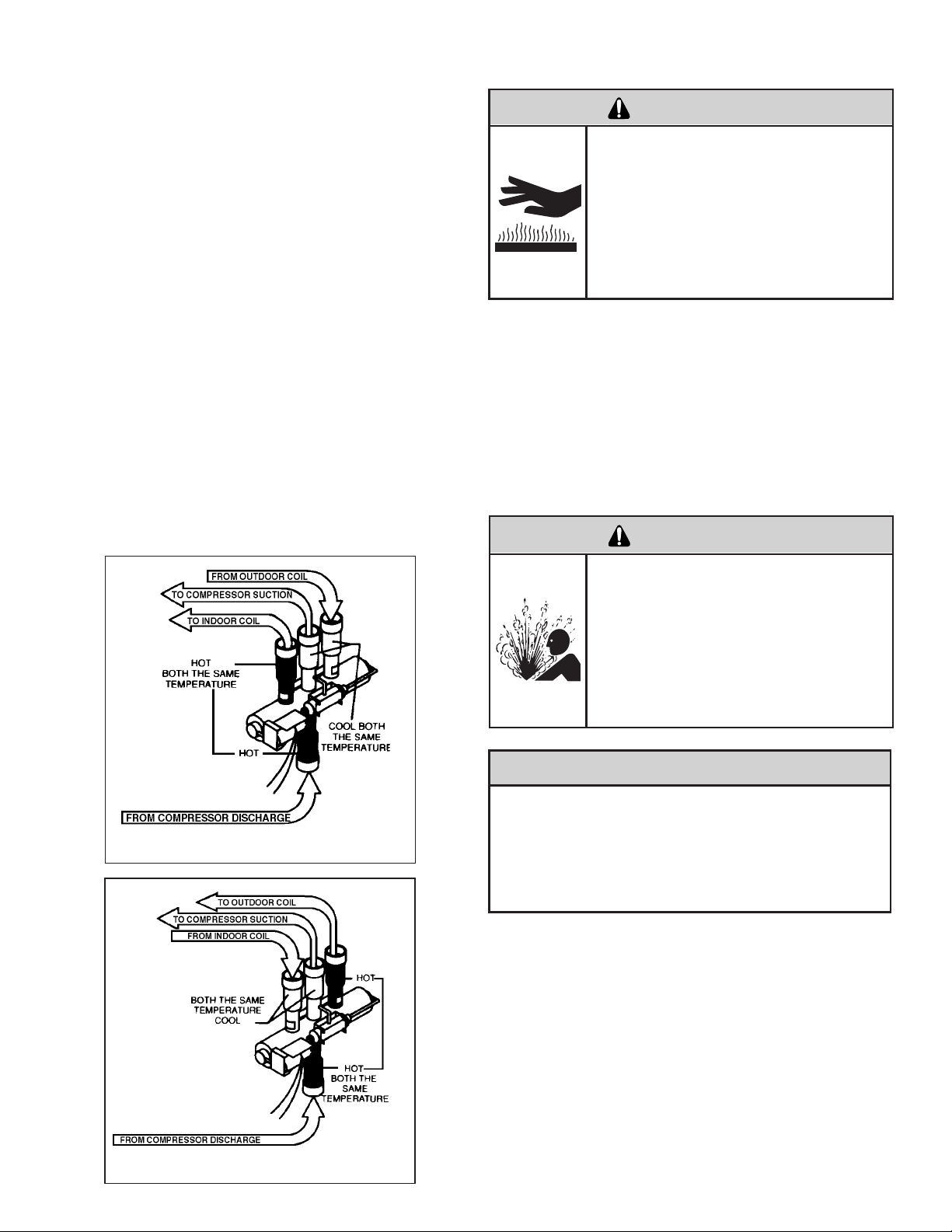
Touch Test in Heating/Cooling Cycle
WARNING
BURN HAZARD
Certain unit components operate at
temperatures hot enough to cause burns.
Proper safety procedures must be followed,
and proper protective clothing must be
worn.
The only definite indications that the slide is in the mid-
position is if all three tubes on the suction side of the valve
are hot after a few minutes of running time.
NOTE: A condition other than those illustrated above, and
on Page 31, indicate that the reversing valve is not shifting
properly. Both tubes shown as hot or cool must be the same
corresponding temperature.
Failure to follow these procedures could
result in minor to moderate injury.
After all of the previous inspections and checks have been
made and determined correct, then perform the “Touch
Test” on the reversing valve.
Reversing Valve in Heating Mode
Procedure For Changing Reversing Valve
WARNING
HIGH PRESSURE HAZARD
Sealed Refrigeration System contains refrigerant
and oil under high pressure.
Proper safety procedures must be followed,
and proper protective clothing must be worn
when working with refrigerants.
Failure to follow these procedures could
result in serious injury or death.
NOTICE
FIRE HAZARD
The use of a torch requires extreme care and proper
judgment. Follow all safety recommended precautions
and protect surrounding areas with re proof materials.
Have a re extinguisher readily available. Failure to follow
this notice could result in moderate to serious property
damage.
26
Reversing Valve in Cooling Mode
1. Install Process Tubes. Recover refrigerant from sealed
system. PROPER HANDLING OF RECOVERED
REFRIGERANT ACCORDING TO EPA REGULATIONS
IS REQUIRED.
2. Remove solenoid coil from reversing valve. If coil is to
be reused, protect from heat while changing valve.
3. Unbraze all lines from reversing valve.
4. Clean all excess braze from all tubing so that they will
slip into ttings on new valve.
5. Remove solenoid coil from new valve.
Page 29
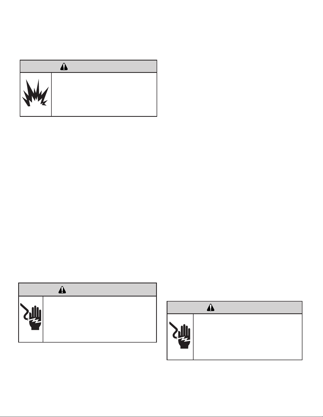
6. Protect new valve body from heat while brazing with plastic
heat sink (Thermo Trap) or wrap valve body with wet
rag.
7. Fit all lines into new valve and braze lines into new
valve.
WARNING
EXPLOSION HAZARD
The use of nitrogen requires a pressure
regulator. Follow all safety procedures and
wear protective safety clothing etc.
Failure to follow proper safety procedures
could result in serious injury or death.
8. Pressurize sealed system with a combination of R-22
and nitrogen and check for leaks, using a suitable leak
detector. Recover refrigerant per EPA guidelines.
9. Once the sealed system is leak free, install solenoid coil
on new valve and charge the sealed system by weighing
in the proper amount and type of refrigerant as shown
on rating plate. Crimp the process tubes and solder the
ends shut. Do not leave Schrader or piercing valves in
the sealed system.
NOTE: When brazing a reversing valve into the system, it is
of extreme importance that the temperature of the valve does
not exceed 250
Wrap the reversing valve with a large rag saturated with
water. “Re-wet” the rag and thoroughly cool the valve after
each brazing operation of the four joints involved.
The wet rag around the reversing valve will eliminate
conduction of heat to the valve body when brazing the line
connection.
COMPRESSOR CHECKS
°F at any time.
Determine L.R.V.
Start the compressor with the volt meter attached; then stop
the unit. Attempt to restart the compressor within a couple
of seconds and immediately read the voltage on the meter.
The compressor under these conditions will not start and will
usually kick out on overload within a few seconds since the
pressures in the system will not have had time to equalize.
Voltage should be at or above minimum voltage of 197 VAC,
as specied on the rating plate. If less than minimum, check
for cause of inadequate power supply; i.e., incorrect wire
size, loose electrical connections, etc.
Amperage (L.R.A.) Test
The running amperage of the compressor is the most important of these readings. A running amperage higher than that
indicated in the performance data indicates that a problem
exists mechanically or electrically.
Single Phase Running and L.R.A. Test
NOTE: Consult the specication and performance section
for running amperage. The L.R.A. can also be found on the
rating plate.
Select the proper amperage scale and clamp the meter
probe around the wire to the “C” terminal of the compressor.
Turn on the unit and read the running amperage on the meter. If the compressor does not start, the reading will indicate
the locked rotor amperage (L.R.A.).
Overloads
The compressor is equipped with an external or internal
overload which senses both motor amperage and winding
temperature. High motor temperature or amperage heats
the overload causing it to open, breaking the common circuit
within the compressor.
Heat generated within the compressor shell, usually due to
recycling of the motor, is slow to dissipate. It may take anywhere from a few minutes to several hours for the overload
to reset.
WARNING
ELECTRIC SHOCK HAZARD
Turn off electric power before service or
installation. Extreme care must be used, if it
becomes necessary to work on equipment with
power applied.
Failure to do so could result in serious injury or
death.
Locked Rotor Voltage (L.R.V.) Test
Locked rotor voltage (L.R.V.) is the actual voltage available
at the compressor under a stalled condition.
Single Phase Connections
Disconnect power from unit. Using a voltmeter, attach one
lead of the meter to the run “R” terminal on the compressor
and the other lead to the common “C” terminal of the com-
pressor. Restore power to unit.
Checking the Overload
WARNING
ELECTRIC SHOCK HAZARD
Turn off electric power before service or
installation. Extreme care must be used, if it
becomes necessary to work on equipment
with power applied.
Failure to do so could result in serious injury or
death.
27
Page 30
WARNING
BURN HAZARD
Certain unit components operate at
temperatures hot enough to cause burns.
Proper safety procedures must be followed,
and proper protective clothing must be
worn.
Failure to follow this warning could result
in moderate to serious injury.
External Overload VPAK 9, 12, 18 K Btus
With power off, remove the leads from compressor termi-
nals. If the compressor is hot, allow the overload to cool
before starting check. Using an ohmmeter, test continuity across the terminals of the external overload. If you
do not have continuity; this indicates that the overload is
open and must be replaced.
Internal Overload VPAK 24 K Btus
The overload is embedded in the motor windings to
sense the winding temperature and/or current draw. The
overload is connected in series with the common motor
terminal.
1. With no power to unit, remove the leads from the com-
pressor terminals. Allow motor to cool.
2. Using an ohmmeter, test continuity between terminals
C-S and C-R. If no continuity, the compressor overload is
open and the compressor must be replaced.
Add values “C” to “S” and “C” to “R” together and check
resistance from start to run terminals (“S” to “R”). Resistance
“S” to “R” should equal the total of “C” to “S” and “C” to “R.”
In a single phase PSC compressor motor, the highest
value will be from the start to the run connections (“S” to
“R”). The next highest resistance is from the start to the
common connections (“S” to “C”). The lowest resistance
is from the run to common. (“C” to “R”) Before replacing a
compressor, check to be sure it is defective.
GROUND TEST
Use an ohmmeter set on its highest scale. Touch one
lead to the compressor body (clean point of contact as a
good connection is a must) and the other probe in turn
to each compressor terminal. If a reading is obtained the
compressor is grounded and must be replaced.
Check the complete electrical system to the compressor
and compressor internal electrical system, check to be
certain that compressor is not out on internal overload.
Internal Overload
Single Phase Resistance Test
WARNING
ELECTRIC SHOCK HAZARD
Turn off electric power before service or
installation. Extreme care must be used, if it
becomes necessary to work on equipment
with power applied.
Failure to do so could result in serious injury or
death.
Remove the leads from the compressor terminals and set
the ohmmeter on the lowest scale (R x 1).
Touch the leads of the ohmmeter from terminals common
to start (“C” to “S”). Next, touch the leads of the ohmmeter
from terminals common to run (“C” to “R”).
Complete evaluation of the system must be made whenever
you suspect the compressor is defective. If the compressor
has been operating for sometime, a careful examination
must be made to determine why the compressor failed.
Many compressor failures are caused by the following
conditions:
1. Improper air ow over the evaporator.
2. Overcharged refrigerant system causing liquid to be
returned to the compressor.
3. Restricted refrigerant system.
4. Lack of lubrication.
5. Liquid refrigerant returning to compressor causing oil
to be washed out of bearings.
6. Noncondensables such as air and moisture in
the system. Moisture is extremely destructive to a
refrigerant system.
28
Page 31

COMPRESSOR REPLACEMENT
Recommended procedure for compressor
replacement
WARNING
RISK OF ELECTRIC SHOCK
Unplug and/or disconnect all electrical power
to the unit before performing inspections,
maintenances or service.
Failure to do so could result in electric shock,
serious injury or death.
1. Be certain to perform all necessary electrical and
refrigeration tests to be sure the compressor is
actually defective before replacing.
WARNING
HIGH PRESSURE HAZARD
Sealed Refrigeration System contains refrigerant
and oil under high pressure.
Proper safety procedures must be followed,
and proper protective clothing must be worn
when working with refrigerants.
Failure to follow these procedures could
result in serious injury or death.
2. Recover all refrigerant from the system though
the process tubes. PROPER HANDLING OF
RECOVERED REFRIGERANT ACCORDING TO
EPA REGULATIONS IS REQUIRED. Do not use
gauge manifold for this purpose if there has been
a burnout. You will contaminate your manifold and
hoses. Use a Schrader valve adapter and copper
tubing for burnout failures.
3. After all refrigerant has been recovered, disconnect
suction and discharge lines from the compressor and
remove compressor. Be certain to have both suction
and discharge process tubes open to atmosphere.
4. Carefully pour a small amount of oil from the suction
stub of the defective compressor into a clean
container.
5. Using an acid test kit (one shot or conventional kit), test
the oil for acid content according to the instructions
with the kit.
6. If any evidence of a burnout is found, no matter how
slight, the system will need to be cleaned up following
proper procedures.
7. Install the replacement compressor.
WARNING
EXPLOSION HAZARD
The use of nitrogen requires a pressure
regulator. Follow all safety procedures and
wear protective safety clothing etc.
Failure to follow proper safety procedures
result in serious injury or death.
8. Pressurize with a combination of R-410A and nitrogen
and leak test all connections with leak detector capable of
detecting HFC (Hydrouorocarbon) refrigerant. Recover
refrigerant/nitrogen mixture and repair any leaks found.
Repeat Step 8 to insure no more leaks are present.
9. Evacuate the system with a good vacuum pump capable
of a nal vacuum of 200 microns or less. The system
should be evacuated through both liquid line and suction
line gauge ports. While the unit is being evacuated, seal
all openings on the defective compressor.
WARNING
HIGH TEMPERATURES
Extreme care, proper judgment and all safety
procedures must be followed when testing,
troubleshooting, handling or working around
unit while in operation with high temperature
components. Wear protective safety aids
such as: gloves, clothing etc.
Failure to do so could result in serious burn
injury.
NOTICE
FIRE HAZARD
The use of a torch requires extreme care and proper
judgment. Follow all safety recommended precautions
and protect surrounding areas with re proof materials.
Have a re extinguisher readily available. Failure to follow
this notice could result in moderate to serious property
damage.
CAUTION
FREEZE HAZARD
Proper safety procedures must be followed,
and proper protective clothing must be worn
when working with liquid refrigerant.
Failure to follow these procedures could
result in minor to moderate injury.
10. Recharge the system with the correct amount of
refrigerant. The proper refrigerant charge will be
found on the unit rating plate. The use of an accurate
measuring device, such as a charging cylinder,
electronic scales or similar device is necessary.
NOTICE
NEVER, under any circumstances, charge a rotary
compressor through the LOW side. Doing so would
cause permanent damage to the new compressor.
29
Page 32

SPECIAL PROCEDURE IN THE CASE OF MOTOR
COMPRESSOR BURNOUT
WARNING
ELECTRIC SHOCK HAZARD
Turn off electric power before service or
installation.
Failure to do so may result in personal injury,
or death.
WARNING
HIGH PRESSURE HAZARD
Sealed Refrigeration System contains refrigerant
and oil under high pressure.
Proper safety procedures must be followed,
and proper protective clothing must be worn
when working with refrigerants.
Failure to follow these procedures could
result in serious injury or death.
WARNING
EXPLOSION HAZARD
The use of nitrogen requires a pressure
regulator. Follow all safety procedures and
wear protective safety clothing etc.
Failure to follow proper safety procedures
result in serious injury or death.
To ensure proper unit operation and life expectancy, the
following maintenance procedures should be performed
on a regular basis
1. Air Filter
To ensure proper unit operation, the air lters should
be cleaned at least monthly, and more frequently if
conditions warrant. The unit must be turned off before
the lters are cleaned.
To remove the air lters, grasp the top of the lter and lift
out of the front cabinet. Reverse the procedure to reinstall
the lters.
Clean the lters with a mild detergent in warm water, and
allow them to dry thoroughly before reinstalling.
2. Coils & Chassis
NOTE: Do not use a caustic coil cleaning agent on coils
or base pan. Use a biodegradable cleaning agent and
degreaser. The use of harsh cleaning materials may
lead to deterioration of the aluminum ns or the coil end
plates.
The indoor coil and outdoor coils and base pan should
be inspected periodically (annually or semi-annually)
and cleaned of all debris (lint, dirt, leaves, paper, etc.)
as necessary. Under extreme conditions, more frequent
cleaning may be required. Clean the coils and base
pan with a soft brush and compressed air or vacuum.
A pressure washer may also be used, however, you
must be careful not to bend the aluminum n pack. Use
a sweeping up and down motion in the direction of the
vertical aluminum n pack when pressure cleaning coils.
1.
Recover all refrigerant and oil from the system.
Remove compressor, capillary tube and lter drier
2.
from the system.
3.
Flush evaporator condenser and all connecting
tubing with dry nitrogen or equivalent. Use approved
ushing agent to remove all contamination from
system. Inspect suction and discharge line for
carbon deposits. Remove and clean if necessary.
Ensure all acid is neutralized.
Reassemble the system, including new drier strainer
4.
and capillary tube.
5.
Proceed with step 8-10 on previous page.
ROUTINE MAINTENANCE
WARNING
ELECTRICAL SHOCK HAZARD!
Turn off electrical power before service or
installation. All eletrical connections and wiring
MUST be installed by a qualied electrician
and conform to the National Code and all local
codes which have jurisdiction. Failure to do so
can result in property damage, personal injury
and/or death.
Note: It is extremely important to insure that none of the
electrical and/or electronic parts of the unit get wet. Be
sure to cover all electrical components to protect them
from water or spray.
3. Decorative Front
The decorative front and discharge air grille may be
cleaned with a mild soap or detergent. Do NOT use
solvents or hydrocarbon based cleaners such as
acetone, naphtha, gasoline, benzene, etc., to clean the
decorative front or air discharge grilles.
Use a damp (not wet) cloth when cleaning the control
area to prevent water from entering the unit, and possibly
damaging the electronic control
4. Fan Motor & Compressor
The fan motor & compressor and are permanently
lubricated, and require no additional lubrication.
5. Wall Sleeve
Inspect the inside of the wall sleeve and drain system
periodically (annually or semi-annually) and clean as
required. Under extreme conditions, more frequent
cleaning may be necessary. Clean both of these areas
with an antibacterial and antifungal cleaner. Rinse both
items thoroughly with water and ensure that the drain
outlets are operating properly.
30
Page 33

ELECTRICAL TROUBLESHOOTING CHART - COOLING
NO COOLING OPERATION
Insure that Fuses
are good and/or that
Circuit Breakers are
on and voltage is 208/230
Compressor and Fan
Motor should now
operate
See Refrigerant Circuit
diagnosis if unit still is
not cooling properly
Fan runs but
Compressor doesn't
Compressor runs but
Blower/Fan doesn't
Set thermostat to
"Cool," and the Temp.
below the present
Room Temp.
Nothing operates,
entire system
appears dead
Line voltage present
at the Transformer
Primary
24 Volts present at
208/230 Volts present
at #1 relay on board?
Y terminals on
t-stat and board?
Problems indicated with
Room Thermostat or
Control Wiring
Replace board
Problems indicated
in Blower Relay
of board
Yes
Yes
Yes
Yes
Yes
Yes
Yes
Yes
Yes
No
No
No
No
No
No
O.K.
O.K.
No
Is Line Voltage present
at Motor Leads?
Check Capacitor, is
Capacitor Good?
Replace Capacitor
Motor should run
Possible motor
problem indicated.
Check motor
thoroughly
Yes
Yes
No
No
No
Supply Circuit
problems, loose
Connections, or bad
Relays/Board
Replace Capacitor
and/or Start Assist
Device
Allow ample time
for pressures to
equalize
Possible Compressor
problem indicated.
See Compressor
Checks
Is Locked Rotor
Voltage a minimum of
197 Volts?
Are Capacitor and (if
so equipped) Start
Assist good?
Have System
Pressures Equalized?
Compressor should
run
Yes
Yes
No
No
No
No
Yes
Compressor and fan
motor should now
operate
See Refrigerant
Circuit Diagnosis if
unit still is not cooling
properly
Yes
Yes
No
Check Supply Circuit’s
jumper at transformer. If
okay, replace board
24 Volts at
“R” Terminal on board
Before continuing
check for Error
Codes, see
electronics control
diagnostics and
test mode, page 15
24V at t-stat and
control wiring?
Defective t-stat
defective control wiring
or transformer
Problems indicated with
Control Transformer
replace board
9K BTU, 12K BTU, & 18K BTU
31
Page 34

ELECTRICAL TROUBLESHOOTING CHART - COOLING
Yes
No
24V at t-stat and
control wiring?
Yes
No
24V at t-stat and
control wiring?
NO COOLING OPERATION
Before continuing
check for Error
Codes, see
electronics control
diagnostics and
test mode, page 15
Yes
Yes
Compressor outdoor
fan motor and indoor
blower should now
operate
See Refrigerant Circuit
diagnosis if unit still is
not cooling properly
Indoor blower runs but
outdoor fan motor and
compressor do not run
Compressor and outdoor
fan motor run but indoor
blower does not run
Set thermostat to
"Cool," move the Temp.
lever below the present
Room Temp.
Nothing operates,
entire system
appears dead
Line voltage present
at the Transformer
Primary
Problems indicated with
Room Thermostat or
Control Wiring
Yes
Yes
Yes
Yes
Yes
Yes
Yes
Yes
Yes
No
No
No
No
No
No
No
O.K.
No
Is Line Voltage present
at Motor Leads?
Check Capacitor, is
Capacitor Good?
Replace Capacitor
Motor should run
Possible motor
problem indicated.
Check motor
thoroughly
Yes
Yes
Yes
No
No
No
Supply Circuit
problems, loose
Connections, or bad
Relays/Board
Replace Capacitor
and/or Start Assist
Device
Allow ample time
for pressures to
equalize
Possible Compressor
problem indicated.
See Compressor
Checks
Is Locked Rotor
Voltage a minimum of
197 Volts?
Are Capacitor and (if
so equipped) Start
Assist good?
Have System
Pressures Equalized?
Compressor should
run
Yes
Yes
No
No
No
No
Yes
Compressor and
outdoor fan motor
should now operate
See Refrigerant
Circuit Diagnosis
if unit still is not
cooling properly
Yes
Insure that Fuses
are good and/or that
Circuit Breakers are
on and voltage is 208/230
O.K.
208/230 Volts present
at #1 relay and “OD”
terminal on board?
208/230 Volts present
at compressor’s
contactor?
Problems indicated
in Blower Relay
of board
Replace board
Check Supply Circuit’s
jumper at transformer. If
okay, replace board
24 Volts at
“R” Terminal on board
24 Volts present at
Y terminals on
t-stat and board?
Problems indicated with
Control Transformer
replace board
Defective t-stat
defective control wiring
or transformer
Check contactor
If defective replace
24K BTU
32
Page 35

ELECTRICAL TROUBLESHOOTING CHART
Replace Reversing Valve
NO
NO
YES
YES
Reversing Valve Stuck
YES
Replace Solenoid Coil
Is the Solenoid
Coil Good?
Is Line Voltage
Present at
Solenoid Valve?
Is Selector Switch
set for Heat?
SYSTEM COOLS WHEN
HEATING IS DESIRED.
HEAT PUMP MODE
HEAT PUMP
33
Page 36

REFRIGERANT SYSTEM DIAGNOSIS COOLING
REFRIGERANT SYSTEM DIAGNOSIS HEATING
Low Load Conditions High Load Conditions Low Load Conditions High Load Conditions
Low Air Flow Across High Air Flow Across Refrigerant System Low Air Flow Across
Indoor Coil Indoor Coil Restriction Outdoor Coil
Refrigerant System Reversing Valve not Reversing Valve not
Overcharged
Restriction Fully Seated Fully Seated
Undercharged Overcharged
Non-Condensables (air)
Undercharged System
Moisture in System Defective Compressor Defective Compressor
LOW SUCTION PRESSURE HIGH SUCTION PRESSURE LOW HEAD PRESSURE HIGH HEAD PRESSURE
LOW SUCTION PRESSURE HIGH SUCTION PRESSURE LOW HEAD PRESSURE HIGH HEAD PRESSURE
PROBLEM PROBLEM PROBLEM PROBLEM
PROBLEM PROBLEM PROBLEM PROBLEM
Low Air Flow Across Outdoor Ambient Too High Refrigerant System Outdoor Ambient Too High
Outdoor Coil for Operation in Heating Restriction For Operation In Heating
Refrigerant System Reversing Valve not Reversing Valve not Low Air Flow Across
Restriction Fully Seated Fully Seated Indoor Coil
Undercharged Overcharged
Defective Compressor
Undercharged Overcharged
Moisture in System Defective Compressor
Non-Condensables (air)
in System
TROUBLESHOOTING CHART - COOLING
TROUBLESHOOTING CHART - HEATING
34
Page 37

COOL WITH ELECTRIC HEAT
NOTE: THE DIAGRAM ABOVE, ILLUSTRATES THE TYPICAL THERMOSTAT WIRING FOR TWO SPEED
FAN OPERATION. SEE THE UNIT CONTROL PANEL FOR THE ACTUAL UNIT WIRING DIAGRAM
AND SCHEMATIC.
ELECTRICAL & THERMOSTAT WIRING DIAGRAM
VEA 09/12/18 with 2.5 KW, 3.4 KW or 5KW
ELECTRIC HEAT
35
Page 38

HEAT PUMP WITH ELECTRIC HEAT
NOTE: THE DIAGRAM ABOVE, ILLUSTRATES THE TYPICAL THERMOSTAT WIRING FOR TWO SPEED
FAN OPERATION. SEE THE UNIT CONTROL PANEL FOR THE ACTUAL UNIT WIRING DIAGRAM
AND SCHEMATIC.
ELECTRICAL & THERMOSTAT WIRING DIAGRAM
VHA 09/12/18 with 2.5 KW, 3.4 KW or 5KW
ELECTRIC HEAT
36
Page 39
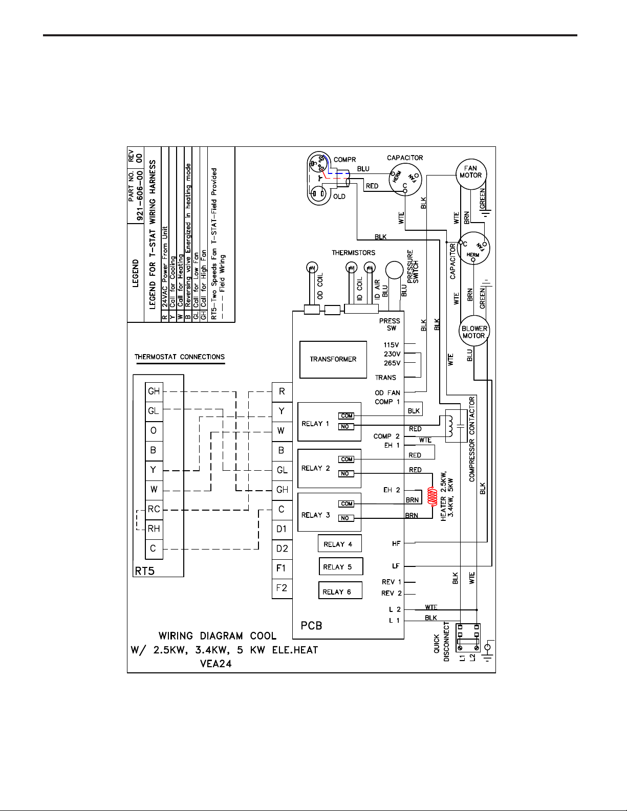
COOL WITH ELECTRIC HEAT
ELECTRICAL & THERMOSTAT WIRING DIAGRAM
VEA 24 with 2.5 KW, 3.4 KW or 5KW ELECTRIC HEAT
37
Page 40

HEAT PUMP WITH ELECTRIC HEAT
ELECTRICAL & THERMOSTAT WIRING DIAGRAM
VHA 24 with 2.5 KW, 3.4 KW or 5KW ELECTRIC HEAT
38
Page 41

COOL WITH ELECTRIC HEAT
ELECTRICAL & THERMOSTAT WIRING DIAGRAM
VEA 24 with 7.5 KW and 10 KW ELECTRIC HEAT
39
Page 42

HEAT PUMP WITH ELECTRIC HEAT
ELECTRICAL & THERMOSTAT WIRING DIAGRAM
VHA 24 with 7.5 KW and 10KW ELECTRIC HEAT
40
Page 43

TECHNICAL SERVICE DATA
VEA09K**RTL 230/208 4.2 58 22 118 156 66 9 24 151 389 33.5
VEA12K**RTL 230/208 5.2 57 23 116 158 59 12 17 141 396 32.0
VEA18K**RTL 230/208 8.1 55 25 127 180 60 12 28 135 455 48.0
VEA24K**RTL 230/208 10.0 55 25 125 170 61 10 34 135 440 65.0
VHA09K**RTL 230/208 4.1 57 23 117 155 62 12 20 155 405 39.0
VHA12K**RTL 230/208 5.3 55 25 119 165 65 15 23 145 450 42.0
VHA18K**RTL 230/208 8.2 51 29 129 190 60 14 35 133 465 45.0
VHA24K**RTL 230/208 10.6 51 29 128 174 60 12 32 140 480 74.0
¹Test Conditions: 80º F, Room Air Temperature with 50% Relative Humidity, and 95º F, Outdoor Air Temperature with 40% Relative Humidity
**Denotes Heater KW - Numbers Vary
Sub-Cooling
OPERATING
PRESSURES
SERVICE DATA
Cooling¹
INDOOR COIL
TEMPERATURE
º F
OUTDOOR COIL
TEMPERATURE
º F
Discharge Line
Temperature
º F
ELECTRICAL
RATINGS
R-410A - Oz.Voltage
Refrigerant
Charge
Supply Air
Temperature
Drop
¨
Suction DischargeAmps
Suction Line
Temperature
º F
Super Heat
TECHNICAL SERVICE DATA
41
Page 44

TECHNICAL SUPPORT
CONTACT INFORMATION
FRIEDRICH AIR CONDITIONING CO.
Post Ofce Box 1540 · San Antonio, Texas 78295-1540
4200 N. Pan Am Expressway · San Antonio, Texas 78218-5212
(210) 357-4400 · 1-800-541-6645 · FAX (210) 357-4490
www.friedrich.com
Printed in the U.S.A.
Printed in the U.S.A.
VPK-ServMan-L (1-10)
Page 45

FRIEDRICH AIR CONDITIONING CO.
Post Ofce Box 1540 · San Antonio, Texas 78295-1540
4200 N. Pan Am Expressway · San Antonio, Texas 78218-5212
(210) 357-4400 · FAX (210) 357-4490
www.friedrich.com
Printed in the U.S.A.
VPK-ServMan-L (1-10)
 Loading...