

Page 1

Room Air Conditioners
Installation and Operation Manual
Standard Chassis Models
115-Volt:
208-230-Volt:
115-Volt:
208-230-Volt:
93001010_00
SS08, SS10, SS12, SS14, SM15
SS12, SS16, SM18, SM21, SM24
SL22, SL24, SL28, SL36
YS10
ES12, ES16, YS12, EM18
YM18, EM24, EL36, YL24
Page 2
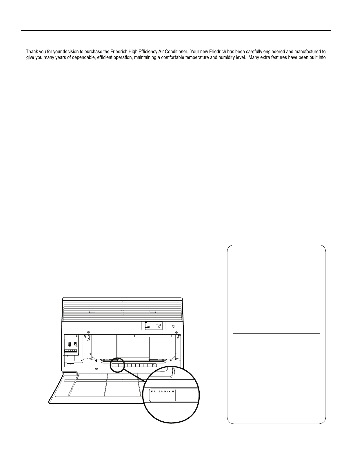
your unit to assure quiet operation, the greatest circulation of cool, dry air, and the most economic operation.
THANK YOU, on behalf of our entire company,
for making such a wise purchase.
AIR CONDITIONING CO.
SAN ANTONIO, TEXAS
ASSEMBLED IN MEXICO
Register your air conditioner
Model information can be found on the name
plate behind the front cover.
Ple a s e c omp l ete an d m ail the o w n e r
registration card furnished with this product,
or register online at www.friedrich.com.
For your future convenience, record the
model information here.
MODEL NUMBER
SERIAL NUMBER
PURCHASE DATE
MODEL NUMBER
HEATING
REFRIGERANT
XXXXXXXXX
XXXXXXXXXX
VOLTS 115
COOLING
YS10M10A
60 HZ / 1 PH
BTH/HR 6500
SERIAL NUMBER
VOLTS MIN 108
EER 12.0
LICY00008
AMPS 8.0
FUSE PROTECTED
U
600 PSIG HS
XXXXXXXXX
CIRCUITS USE 15A
300 PSIG LS
XXXXXXXXXX
TIME DELAY FUSE
XXXXXXXXXX
L
X XX
XXXXX
XXXXXXXXXX
AIR CONDITIONING CO.
SAN ANTONIO, TEXAS
ASSEMBLED IN MEXICO
MODEL NUMBER
YS10N10
SERIAL NUMBER
LICY00008
BTH/HR 6500
30.1 OZ R410A
EER 10.4
AMPS 7.0
2
Page 3
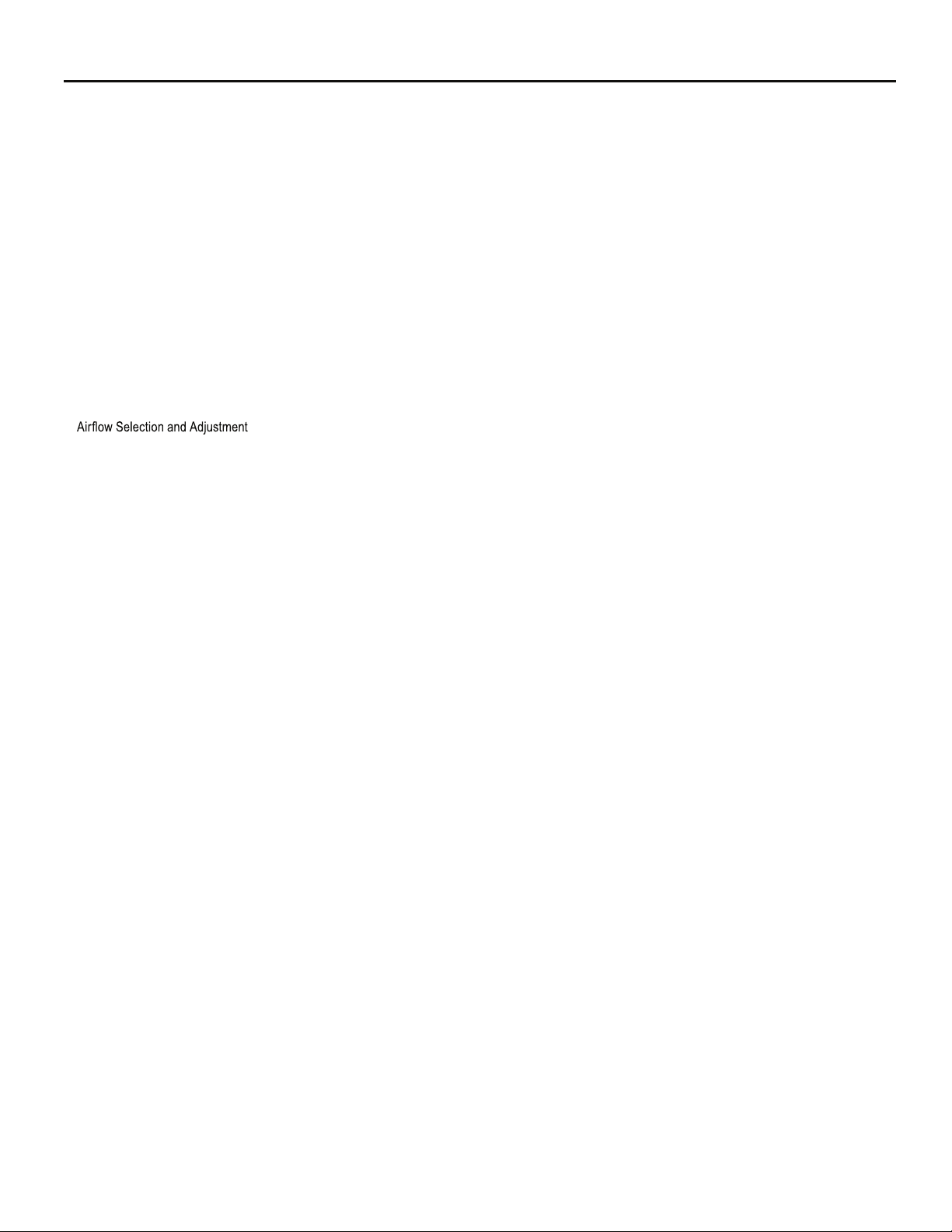
Table of Contents
Safety Precautions ................................................................................................................................................................................................................... 4
Unpacking Instructions............................................................................................................................................................................................................. 5
WARNING: Before Operating Your Unit ..................................................................................................................................................................................6
Standard Filter Cleaning / Installation Instructions .................................................................................................................................................................. 7
Premium Carbon Filter Installation Instructions .......................................................................................................................................................................8
Control Panel Operation ......................................................................................................................................................................................................... 9
New Kühl Control Options ...................................................................................................................................................................................................... 10
Control Panel Operation Instructions ............................................................................................................................................................................................... 11
Remote Control Operation ..................................................................................................................................................................................................... 20
Remote Effectiveness ............................................................................................................................................................................................................ 20
.......................................................................................................................................................................................... 22
Installation Instructions .......................................................................................................................................................................................................... 23
Standard Window Installation ................................................................................................................................................................................................ 25
Cord Routing Change ............................................................................................................................................................................................................34
Through-the-Wall Installation ................................................................................................................................................................................................. 36
Final Inspection & Start-up Checklist..................................................................................................................................................................................... 40
Routine Maintenance .............................................................................................................................................................................................................41
Service and Assistance .........................................................................................................................................................................................................41
Available Accessories ............................................................................................................................................................................................................41
Troubleshooting Tips .............................................................................................................................................................................................................. 42
Addendum 1 ........................................................................................................................................................................................................................... 44
Warranty ..... ........................................................................................................................................................................................................................... 45
3
Page 4

Safety Precautions
We have provided many important safety messages in this manual and on your appliance. Always read and obey all
safety messages.
All safety messages will tell you what the potential hazard is, tell you how to reduce the chance of injury, and tell you
what will happen if the instructions are not followed.
Your safety and the safety of others are very important.
This is a safety Alert symbol.
This symbol alerts you to potential hazards that can kill or hurt you and others.
All safety messages will follow the safety alert symbol with the word “WARNING”
or “CAUTION”. These words mean:
WARNING
CAUTION
Indicates a hazard which, if not avoided, can result in severe personal injury or
death and damage to product or other property.
Indicates a hazard which, if not avoided, can result in personal injury and
damage to product or other property.
NOTICE
Indicates property damage can occur if instructions are not followed.
WARNING
Refrigeration system
under high pressure
Do not puncture, heat, expose to flame or
incinerate.
Only certified refrigeration technicians should
service this equipment.
R410A systems operate at higher pressures
than R22 equipment. Appropriate safe
service and handling practices must be used.
Only use gauge sets designed for use with
R410A. Do not use standard R22 gauge sets.
4
Page 5

Unpacking Instructions
STEP 5. Slide the foam front support forward
STEP 1. Cut all 4 packing straps.
STEP 2. Remove wooden shipping bar dividers.
STEP 3. Remove top foam pads.
STEP 4. Slowly remove outer box, careful not to loosen decorative front.
STEP 6. Carefully lift decorative front box from foam front support
STEP 7. Remove decorative front and set safely aside
5
Page 6

WARNING
NOTICE
Electrical Shock Hazard
Make sure your electrical receptacle has the
same configuration as your air conditioner’s
plug. If different, consult a Licensed Electrician.
Do not use plug adapters.
Do not use an extension cord.
Do not remove ground prong.
Always plug into a grounded 3 prong oulet.
Failure to follow these instructions can result in
death, fire, or electrical shock.
Make sure the wiring is adequate for your unit.
If you have fuses, they should be of the time delay type. Before you install
or relocate this unit, be sure that the amperage rating of the circuit breaker
or time delay fuse does not exceed the amp rating listed in Table 1.
DO NOT use an extension cord.
The cord provided will carry the proper amount of electrical power to the
unit; an extension cord may not.
Make sure that the receptacle is compatible with
the air conditioner cord plug provided.
Proper grounding must be maintained at all times. Two prong receptacles
The grounded receptacle should meet all national and local codes and
ordinances. You must use the three prong plug furnished with the air
conditioner. Under no circumstances should you remove the ground
prong from the plug.
Test the power cord
All Friedrich room air conditioners are shipped from the factory with a
Leakage Current Detection Interrupter (LCDI) equipped power cord. The
LCDI device on the end of the cord meets the UL and NEC requirements
f
or cord connected air conditioners.
To test your power supply cord:
1. Plug power supply cord into a grounded 3 prong outlet.
2. Press RESET (See Figure 1).
3. Press TEST, listen for click; the RESET button trips and pops out.
4. Press and release RESET (Listen for click; RESET button latches
and remains in). The power cord is ready for use.
Do not use the LCDI device as an ON/OFF switch.
Failure to adhere to this precaution may cause
premature equipment malfunction.
Once plugged in, the unit will operate normally without the need to reset
the LCDI device. If the LCDI device fails to trip when tested or if the power
supply cord is damaged, it must be replaced with a new power supply cord
from the manufacturer. Contact our Technical Assistance Line at (800)
541-6645. To expedite service, please have your model number available.
Table 1.
CIRCUIT RATING
OR TIME DELAY
MODEL
FUSE
AMP VOLT
SS08, SS10
SS12, SS14
15 125 5-15R
YS10, SM15
SS12, SS16
SM18, SM21 15 250 6-15R
SL22
SM24
, SL28
ES12, ES16
20 250 6-20R
YS12, SL24
SL36, EM18
EM24,
EL36
30 250 6-30R
YM18, YL24
Figure 1
RESET
TEST
WARNING:
TEST BEFORE EACH USE!
1.PRESS REST BUTTON.
2.PLUG LCDI INTO POWER
RECEPTACLE.
3.PRESS TEST BUTTON,
RESET BUTTON SHOULD
POP UP.
4.PRESS RESET BUTTON
FOR USE.
DO NOT USE IF ABOVE TEST
FAILS.
WHEN GREEN LIGHT IS ON.
IT IS WORKING
PROPERLY!
REQUIRED
WALL
RECEPTACLE
NEMA
NO.
FRR072
6
Page 7

Standard Filter Cleaning / Installation Instructions
STEP 1.
Figure 2
FRR071
STEP 2.
NOTE:
Figure 4
FILTER
FILTER
GRIP
Figure 3
FILTER
GRIP
HANDLE
FRR052
FRR047
STEP 3. Swing the front frame open. Clean the front frame by washing
Figure 5
A
TOP TAB
FRONT
FRAME WITH
STANDARD
MESH FILTER
FRR048
STEP 4.
NOTE:
the tab in the frame stops the handle from sliding in, slide the
handle from the other direction. Do not force the handle into
the frame.
STEP 5.
the inside of the front door.
7
Page 8
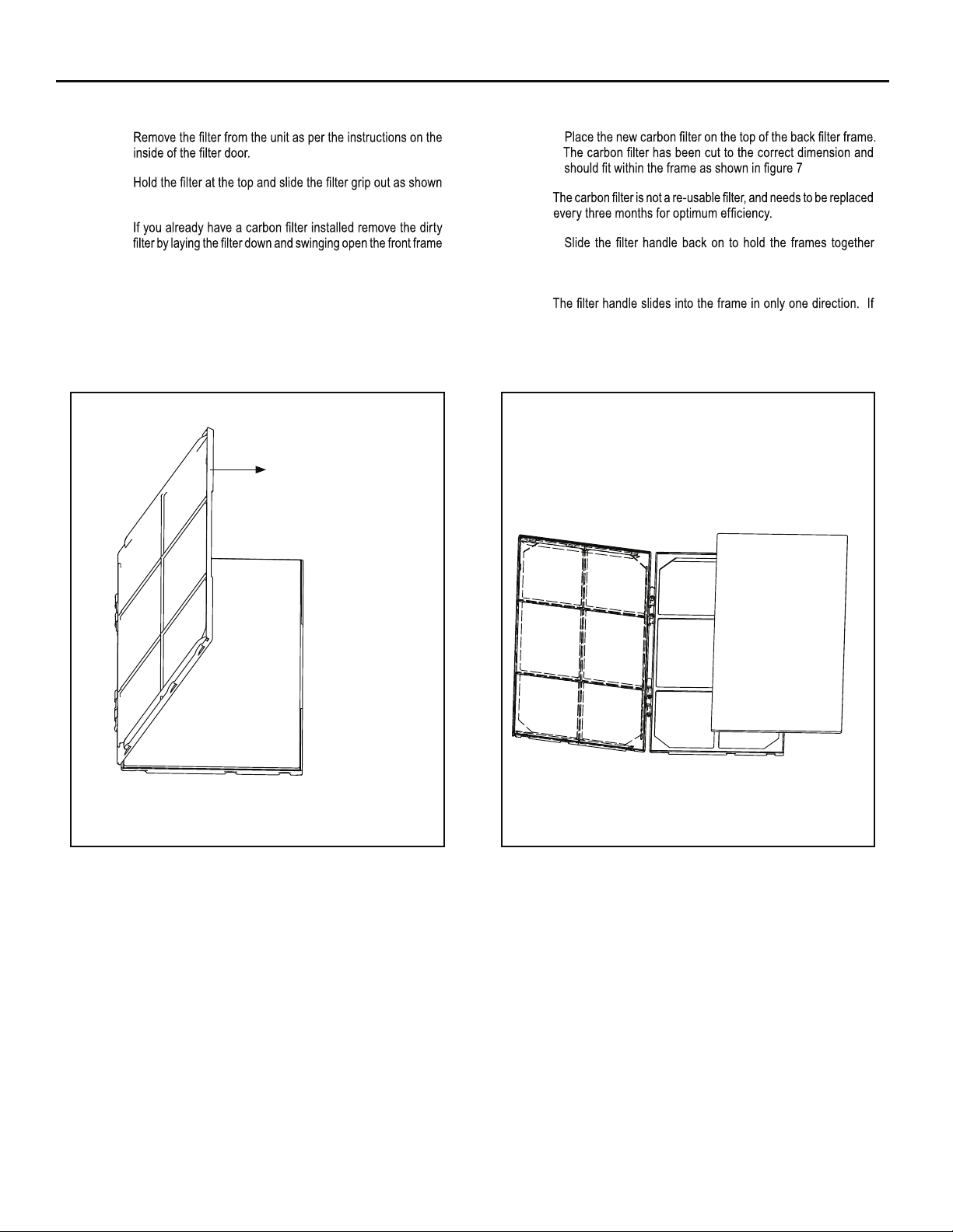
Premium Carbon Filter Installation Instructions
STEP 1.
STEP 4.
STEP 2.
in Figure 4.
STEP 3.
as shown in Figure 6.
NOTE: Make sure the frame with the mesh is facing towards you.
Figure 6
FRONT FRAME WITH
MESH FILTER
NOTE:
STEP 5.
and slide the assembly into the unit as per the instructions
on the door.
NOTE:
the tab in the frame stops the handle from sliding in, slide the
handle from the other direction. Do not force the handle into
the frame.
Figure 7
FRR051FRR050
8
Page 9
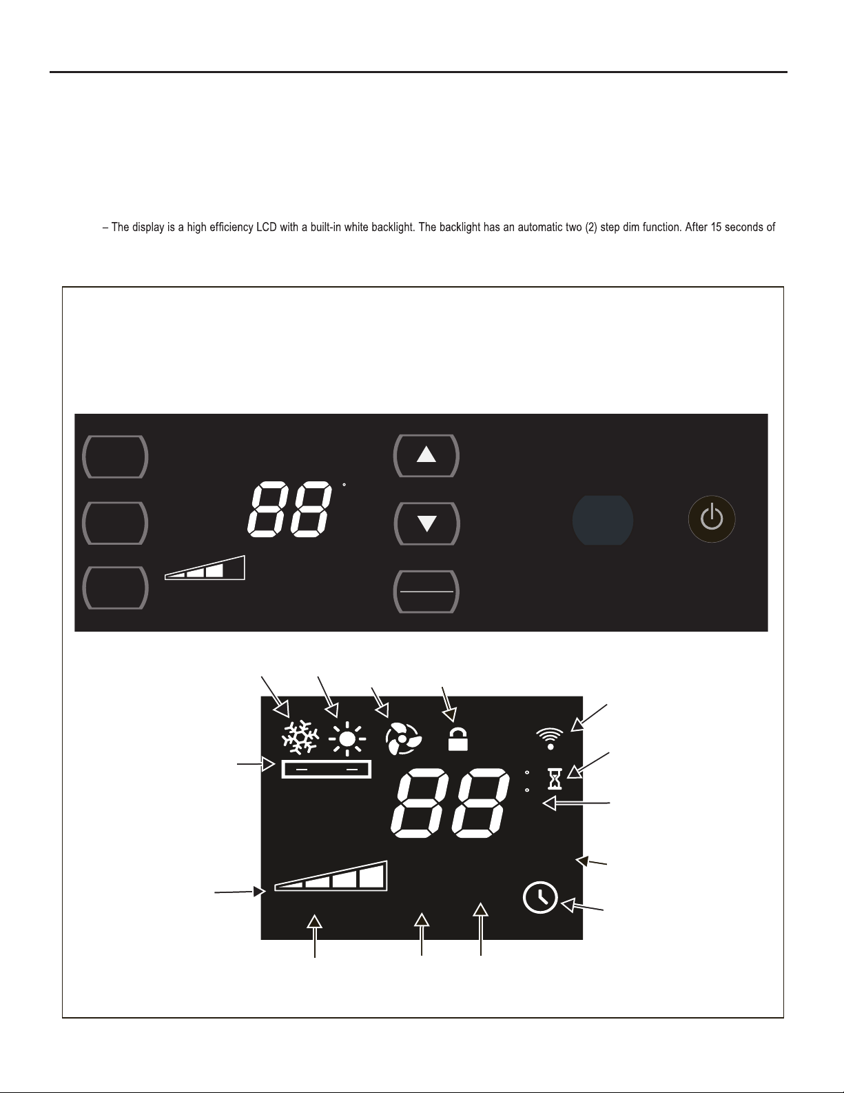
Control Panel Operation
Let’s check out how to control your air conditioner. On the control panel, just above the POWER , is a liquid crystal display (LCD). All of the control panel function
buttons and mode icons can be viewed in Figure 8.
Power On – Press the button to turn on the air conditioner. The power button illuminates to indicate that the power is on. The backlight on the po
we
r switch
will automatically dim to 20% intensity after 15 seconds of inactivity. The remote control can also be used to turn power ON / OFF (See Remote Control).
Display
inactivity, the display dims to 20% intensity. After an additional 120 seconds, the display switches off. Touching any button automatically changes the display
to full brightness.
There are three control push buttons on each side of the display.
Figure 8
SYSTEM
Cycles between
AUTO, HEAT,
COOL, or FAN
ONLY
(if equipped)
FAN MODE
Sets fan to either:
- Cycle automatically
-
Run continuously
FAN SPEED
Sets fan speed:
LOW, MED,
HIGH or AUTO
(if equipped)
TEMPERATURE
Increment UP
TEMPERATURE:
Increment DOWN
TIMER / SCHEDULE
Turns ON or OFF
IR WINDOW
Do not block
:
ON / OFF
Turns unit on/off
SYST EM
F
FAN
MODE
SET POINT
FAN
SPEED
AUTO SPEED
TIMER
SCHEDULE
COOL FAN
AUTO
Automatically switches
between cool & heat
FAN SPEED
Selected fan speed
HEAT
AUTO
AUTO FAN
CONTINUOUS
AUTO SPEED
AUTO SPEED
Automatically
selects best fan
cooling speed
ONLY
CONTROL
LOCKED
SET POINT
ROOM TEMP
CHECK
FILTER
FILTER
Check / Clean
F
C
AM
PM
ON OFF
SCHEDULE
$MART
$MART OPERATING
(if equipped)
WI-FI
OPERATING
(if equipped)
WAIT
2 DIGIT DISPLAY
Shows Setting for:
- Set Point (Temperature)
- Room Temperature
- Clock (AM/PM)
SCHEDULE ON
TIMER ON
9
Page 10

New Kühl Control Options
The new Kühl gives you a variety of options for control, programming, and
scheduling including wireless capabilities
Wireless Programming and Control:
. The new FriedrichLink™ Adapter (sold seperately) allows you to conviently
control, program and monitor your air conditioning unit remotely from a
smartphone or computer.
FriedrichLink™ Adapter accessory available through Friedrich authorized
retailers or www.friedrich.com. See FriedrichLink™ Adapter section on
www.friedrich.com for complete details.
Pre-Programmed Scheduling Options:
Your unit’s digital control comes equipped with a 24-hour timer and two preprogrammed 7-day energy management options.
24-Hour Timer
The 24-hour timer allows you to turn the unit off and on at pre-set times by
setting an on and off time on the unit control panel. (See page 12 for details on
timer set-up.)
Pre-programmed Energy Management
Your unit comes from the factory with two (2) Pre-program
Management settings are shown in Addendum 1 (Residential & Commercial
Schedule Table).
Energy Management Schedule Options are:
1. Residential Schedule – 40 Hr. Work Week
2. Commercial Schedule – 5-Day Business Week
med
Energy
The “Residential” (40 Hr. Work Week) Schedule has four (4) time periods: 06:00,
08:00, 18:00, and 22:00. This option will cause your Kühl Q unit to raise the room
temperature temporarily to 85°F during the hours wh
en most people are away
at work, lower them again to 78°F prior to the time when most people will return
home, and then raise slightly to 82°F to maintain a comfortable temperature
overnight.
The “Commercial” (5-Day Business Week) Schedule has two (2) time periods:
07:00 and 18:00. This option will cause your air conditioner to raise temperatures
to 84°F after typical working hours and on weekends when commercial spaces
r
a
e typically unoccupied.
(See Control Panel Operation Instructions Section)
Customizable Programming Options:
Customizable schedules, with up to four temperature adjustments per day, can
either be uploaded to the unit via the air conditioner’s built-in micro USB interface
or conveniently transmitted wirelessly using the new FriedrichLink™ Adapter
accessory, greatly simplifying the programming of one or multiple units.
See Figure 9.
See www.friedrich.com for complete details on
FriedrichLink.
Figure 9
10
FriedrichLink™ Adapter
AIR CONDITIONING CO.
SAN ANTONIO, TEXAS
ASSEMBLED IN MEXICO
MODEL NUMBER
HEATING
REFRIGERANT
XXXXXXXXX
XXXXXXXXXX
VOLTS 115
COOLING
YS10M10A
60 HZ / 1 PH
BTH/HR 6500
SERIAL NUMBER
VOLTS MIN 108
EER 12.0
LICY00008
AMPS 8.0
FUSE PROTECTED
U
L
BTH/HR 6500
EER 10.4
AMPS 7.0
X XX
30.1 OZ R410A
600 PSIG HS
XXXXXXXXX
CIRCUITS USE 15A
XXXXX
300 PSIG LS
XXXXXXXXXX
TIME DELAY FUSE
XXXXXXXXXX
XXXXXXXXXX
Page 11

Control Panel Operation Instructions
SYSTEM - The
modes of operation:
SYSTEM
button allows you to sequentially select up to four
AUTO
- AUTO -
Not available on some models
COOL
HEAT
Not available on some models
FAN ONLY
AUTO MODE
- AUTO -
AUTO FAN
SET POINT
F
COOL MODE
FRR204
FAN ONLY MODE
FRR105
When in the
- AUTO-, COOL or HEAT or FAN ONLY mode,
you can also select FAN MODE, FAN SPEED, TIMER SCHEDULE,
. The SYSTEM MODE does not change.
and
FAN MODE – The
CONTINUOUS
modes.
FAN
MODE
button allows you to select between
AUTO FAN
AUTO FAN (No Cooling Demand)
AUTO FAN
F
and
AUTO FAN
SET POINT
HEAT MODE
AUTO FAN
SET POINT
FAN SPEED - Depending on your model, the
F
When in the
AUTO FAN
mode, the fan only operates when the system has
SET POINT
a demand to cool or heat the room. Note: the fan is off (no fan speed icon),
FRR103
indicating no command for cooling or heating.
AUTO FAN (Cooling Demand)
F
FRR104
N
FAN
SPEED
button allows you to toggle between four or five modes of operation: LOW, MEDIUM, HIGH and AUTO.
System has a demand for cooling. The fan is operating at a medium speed.
AUTO FAN
SET POINT
F
AUTO
FRR112
FRR106
4 Speed
AUTO
3 Speed
When fan speed AUTO FAN mode (SYSTEM mode AUTO, COOL or HEAT) is selected, fan speed automatically varies depending on the difference between
the unit’s set point on the control panel and the actual room temperature. When the system detects a wide difference between the set point and the actual
room temperature the fan speed increases to HIGH for a period of time. The fan speed decreases, in step, as the temperature difference decreases. When the
room temperature matches the system's set point, fan speed returns to the origin
al setting.
11
Page 12
CONTINUOUS
CONTINUOUS
The
F
SET POINT
FRR113
In the
CONTINUOUS
fan mode, the fan operates all the time. The system
UP and DOWN - arrows - Pressing either or button changes
the system's set point (desired room temperature). These buttons are also
used to make system parameter changes later in this manual.
AUTO FAN
SET POINT
F
FRR100
AUTO FAN
F
SET POINT
FRR123
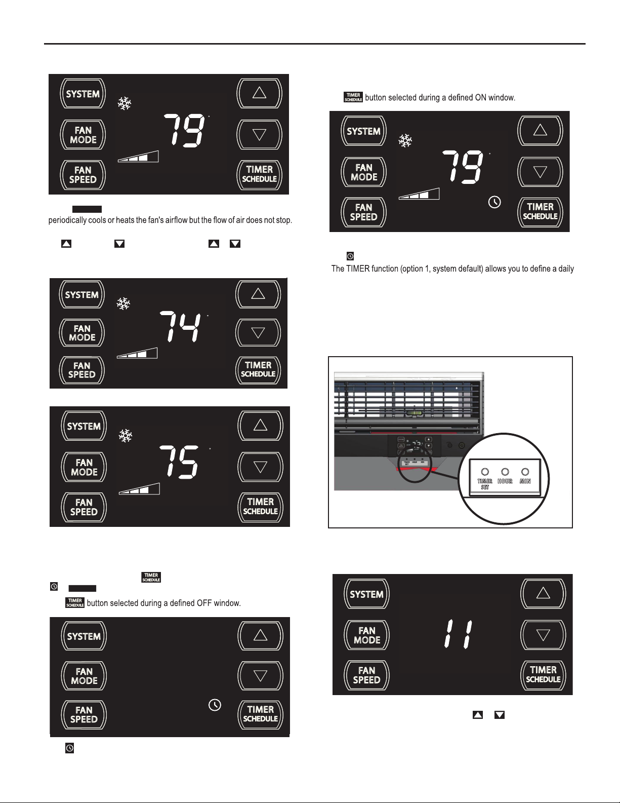
The icon illuminates.
system ON and OFF time window. For example, you can command the
system to turn ON at 8:15 am and turn OFF at 1:30 pm everyday.
The SCHEDULE function allows you to choose either Residential (option
2) or Commercial (option 3). The Residential and Commercial options are
described later in this manual.
OTHER FUNCTIONS
Figure 10
AUTO FAN
SET POINT
F
FRR101
One press equals 1 degree of change. Holding the button down for more
than 0.6 seconds starts the fast increment/decrement change of the set
point.
TIMER SCHEDULE - The
SCHEDULE
or
function.
button allows you to select the TIMER
The
The icon illuminates.
FRR122
12
SET TIME- To adjust the unit's time press and hold the HOUR and the MIN
buttons for three seconds (Refer to Figure 10).
AM
FRR128
The unit's current hour displays. Use the or buttons to adjust the
hour. To change from AM to PM continue to increment (roll) the display.
Press TIMER SET (Refer to Figure 10) button to display the unit's current
minutes.
Page 13
FRR129
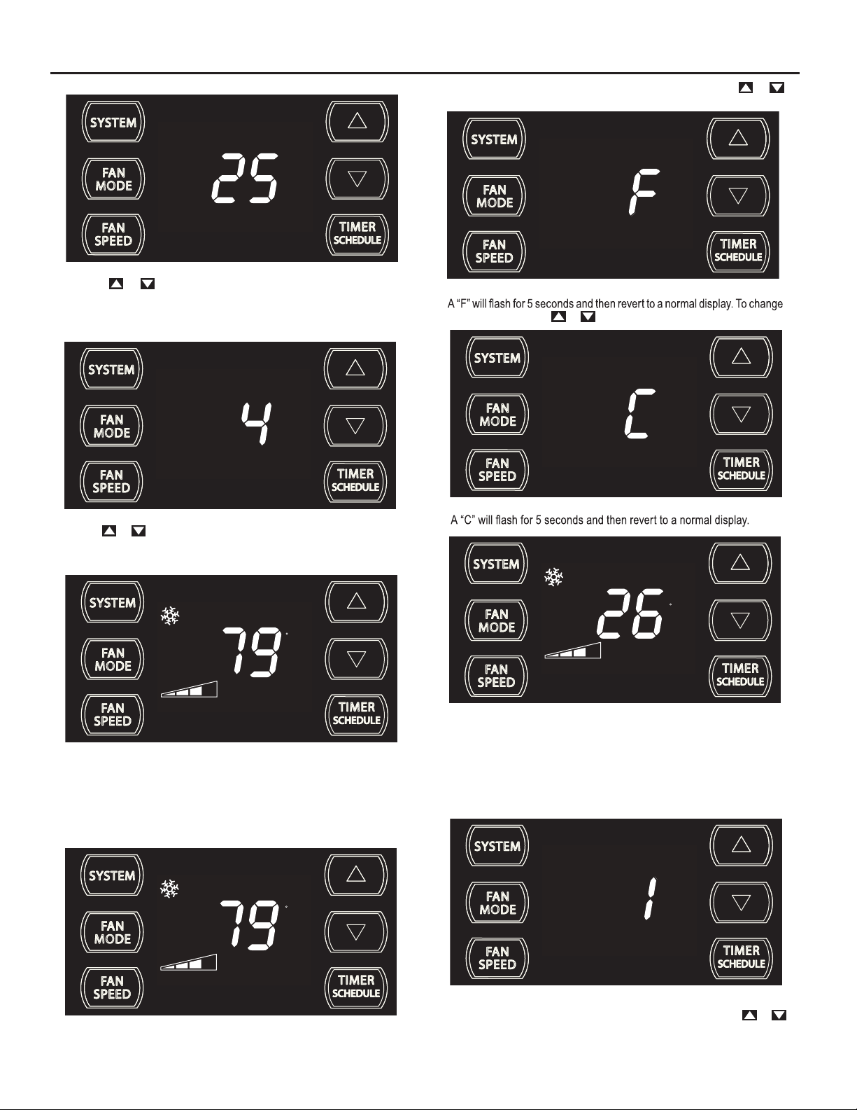
Use the or buttons to adjust the minutes. The clock is now set
for 11:25 AM. Press TIMER SET (Refer to Figure 10) button to display the
unit's day setting.
To switch from degrees Fahrenheit (F) to Celsius (C), press &
buttons for three seconds.
FRR133
from F to C, press the or button within 5 seconds.
FRR130
Use the or buttons to adjust the day (1 to 7). The day setting is up
to
you the user. If you set the current day = 1, and today is Tuesday,
then Day 1 = Tuesday.
AUTO FAN
SET POINT
F
FRR131
Press TIMER SET (Refer to Figure 10) button to exit and save the SET
TIME function. The TIMER SET button must be pressed within 15 second.
Button inactivity for more than 15 seconds causes the display to time out
and return to the normal operating display.
ºF - ºC Select
AUTO FAN
F
FRR134
AUTO FAN
SET POINT
C
FRR135
The ºF icon goes away and the ºC icon illuminates on the normal display.
DIM Function
There are three separate display brightness levels, AUTO, 20% and full
(100%). To change the DIM setting, press the Power button for three
seconds.
SET POINT
FRR132
FRR192
The 1 indicates a DIM setting of Auto (factory default). Use the or
buttons to change the setting.
13
Page 14
AUTO FAN
F
SET POINT
FRR193
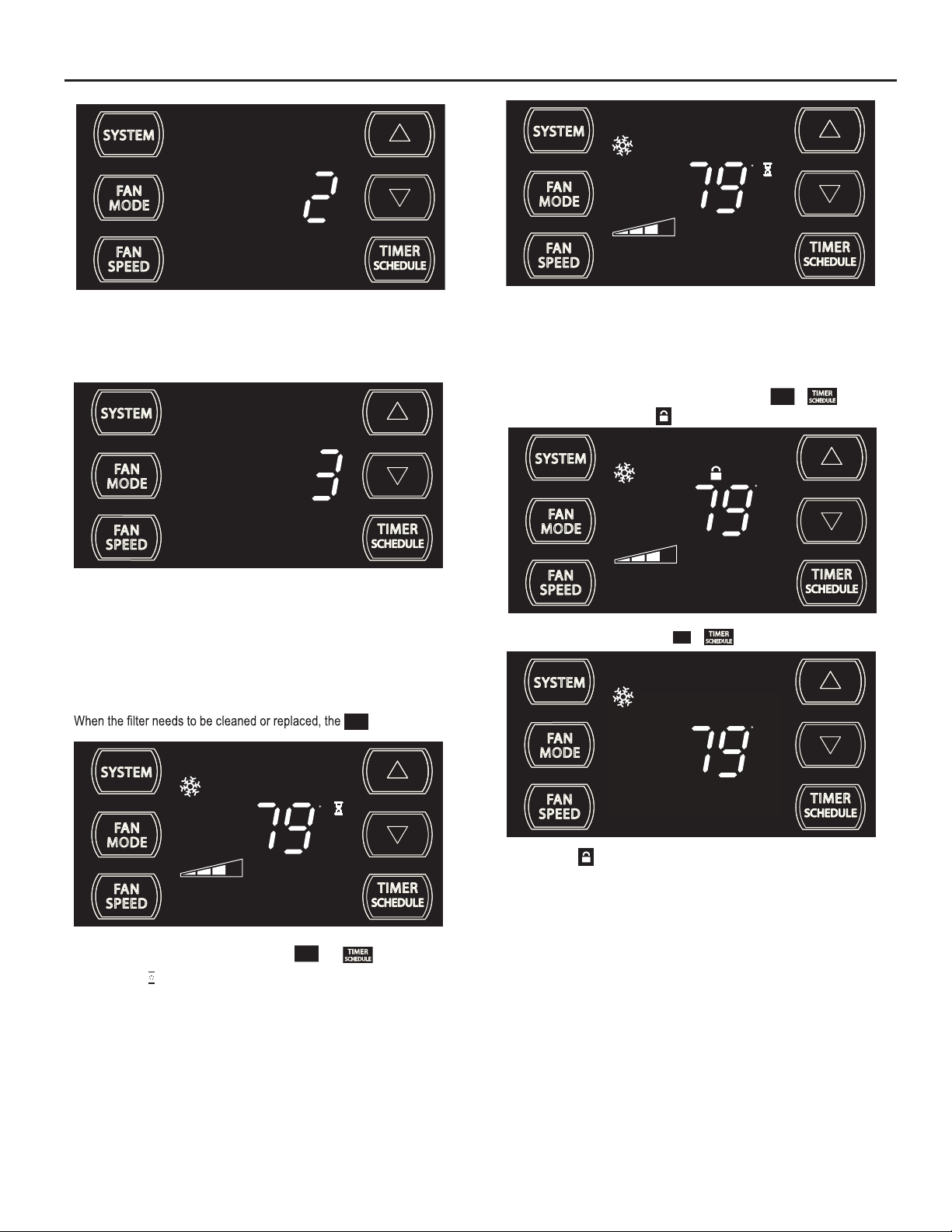
The 2 indicates a DIM setting of 20%. Press the TIMER SET button within
15 seconds to save the setting. Button inactivity for more than 15 seconds
causes the display to time out and return to the normal operating display.
FRR194
The 3 indicates a DIM setting of 100% (full brightness). Press the TIMER
SET (Refer to Figure 10) button within 15 seconds to save the setting.
Button inactivity for more than 15 seconds causes the display to time out
and return to the normal operating display.
Alerts
CHECK
icon displays.
FILT ER
This means there is a compressor demand but the system is not ready
FRR120
for the compressor to operate. For example a short power outage, the
compressor will not restart until the internal pressures of the compressor
are at the proper level.
Lock Control Panel
To lock the front panel controls, press and hold the
for 3 seconds. The lock icon
AUTO FAN
To unlock, presses and hold the
AUTO FAN
illuminates to indicate the locked status.
SET POINT
FAN
SPEED
+ buttons for 3 seconds.
FAN
SPEED
F
F
+ buttons
16
FRR1
AUTO FAN
SET POINT
FILTER
The alert can be dismissed by pressing the
F
FAN
MODE
and for 3 seconds.
FRR118
The wait icon illuminates when the compressor 3 minute time delay is
active.
14
SET POINT
The lock icon disappears to indicate unlocked status.
FRR117
Page 15

External Control Status
$MART
The
remotely from a source such as a smart grid.
icon illuminates to indicate that the system is being controlled
When selected the unit
3. Commercial Schedule (Selection #2) -
follows a preprogrammed set of operational parameters that covers 7
days of the week with 2 time windows during each day. Each time window
has it's own set of 6 operating parameters. Refer to Addendum 1.
AUTO FAN
79
SET POINT
AUTO FAN
79
SET POINT
The icon illuminates to indicate that the system is receiving a Wi-Fi
connection.
ADVANCED FUNCTIONS
Let me put in plain words many of your unit's advanced functions (Timer,
Schedule, Error Mode, Test Mode, and Maintenance Menu). The functions
mentioned in the following section may or may not be available depending
on the air conditioner model.
Timer/Schedule Select
F
$MART
FRR125
F
FRR126
1
To change the selection, press and hold the TIMER/SCHEDULE
button for 3 sec.
If the Schedule function is available, the system displays the
SCHEDULE
icon. The display indicates the schedule function that is active.
To change to an alternate schedule (2 or 3), press the
If the Schedule function is not available, the Timer icon
SCHEDULE
the
To save and exit this selection, press the TIMER SET button for 3
seconds (Figure 10).
If there is no button activity for 15 seconds, the function will time out and
leave the original selection. Once the selection is saved or timed out, the
display reverts to the normal display.
icon.
2
SCHEDULE
FRR137
or button.
shows without
SCHEDULE
+ noci
AUTO FAN
79
SET POINT
The control system has three Timer/Schedule functions:
1.
Timer (factory default) - Allows you to command the unit to turn
ON and OFF at time you program within a 7 day window. Setting
the start, stop and day window can be found later in this manual.
2.
Residential Schedule (Selection #1) - When selected the unit
follows a preprogrammed set of operational parameters that
covers 7 days of the week with 4 time windows during each day.
Each time window has it's own set of 6 operating parameters.
Refer to Addendum 1.
F
FRR136
FRR138
After pressing the or button, within 15 second of pressing the
button for 3 seconds, the display indicates a change to Timer/Scheduler
2. To save and exit this selection, press the TIMER SET button (Figure 10).
AUTO FAN
79
SET POINT
The display reverts to the normal display.
F
FRR136
15
Page 16

AUTO FAN
FRR146
79
SET POINT
F
FRR139
To turn on the timer or schedule selected, press and release the
button and the selected system will operate in the mode (1, 2 or 3).
Modify the TIMER Function
Timer Start Time
AUTO FAN
79
SET POINT
The display shows a normal system. Press and hold the HOUR button
(Figure 10) for 3 seconds. Note the Timer start-stop times may be set even
when the system is in the Timer or Schedule mode.
4
F
FRR140
AM
ON
FRR143
The display returns to normal once the settings are saved.
Timer Stop Time
AUTO FAN
79
SET POINT
The display shows a normal system. Press and hold the MIN button (Figure
10) for 3 seconds. Note the Timer start - stop times may be set even when
the system is in the Schedule mode.
11
F
FRR144
AM
OFF
FRR141
Use the or button to adjust the hour. Press the TIMER SET button
(Figure 10 10) to adjust the minutes.
21
Use the or button to adjust the minutes. Press the TIMER SET
button (Figure 10) within 15 seconds to exit and save the setting. The timer
is now set to start at 4:21 AM.
16
ON
FRR142
FRR145
Use the or button to adjust the hour. Press the TIMER SET button
(Figure 10) to adjust the minutes.
55
Use the or button to adjust the minutes. Press the TIMER SET
button (Figure 10) within 15 seconds to exit and save the setting. The timer
is now set to stop at 11:55 AM.
OFF
Page 17

FRR148
SET POINT
F
AUTO FAN
79
SCHEDULE
FRR149
Schedule ON Scenarios
AUTO FAN
79
SET POINT
The display returns to normal once the settings are saved.
Timer - Scheduler Control Block
AUTO FAN
79
SET POINT
If the unit is operating in the TIMER or SCHEDULE mode, and then you
press any button except the button, the Timer icon begins
to blink. All button action is blocked. The Timer icon stops blinking after 3
seconds.
F
FRR147
F
SCHEDULE
AUTO FAN
79
SET POINT
The display shows a normal system.
If the Schedule function is turned ON during normal operation, the
and Timer
current period schedule parameters.
F
SCHEDULE
FRR154
SCHEDULE
FRR153
eht snur yletaidemmi metsys lortnoc ehT .setanimulli snoci
AUTO FAN
79
SET POINT
You must turn the active Timer or Schedule mode OFF before making
changes. Once the changes are made, press the button to
re-activate Timer or Schedule mode.
Timer or schedule mode is re-activated.
F
FRR150
17
Page 18

Timer ON Scenarios
Scenario 1
AUTO FAN
79
SET POINT
The display shows a normal operating system.
If the Timer function is turned ON during the Off time, the icon
illuminates. The control system immediately turns the unit OFF.
Scenario 2
F
FRR156
FRR157
AUTO FAN
79
SET POINT
If the Timer function is turned ON during the ON time, the Timer
illuminates. The control system continues to run.
Scheduler OFF Scenarios
Scenario 1
AUTO FAN
79
SET POINT
The display shows the unit in Schedule mode.
F
F
SCHEDULE
FRR159
noci
FRR160
AUTO FAN
79
SET POINT
The display shows a normal operating system.
18
F
FRR158
If the Schedule function is turned OFF during a schedule’s active state
(not off), the Timer and icons turn off. The control stays in the
current state.
The display shows a normal operating system.
Scenario 2
The display shows the unit in Schedule mode during an in-active (OFF)
period.
AUTO FAN
SCHEDULE
79
SET POINT
F
FRR161
SCHEDULE
FRR162
Page 19

AUTO FAN
F
AUTO FAN
F
79
SET POINT
FRR163
If the Schedule function is turned OFF during an in-active (OFF) period,
the Timer
known non-schedule state.
Timer OFF Scenarios
The display shows the unit in Timer mode during an in-active (OFF) period.
and
SCHEDULE
icons turn off. The unit wakes up in the last
FRR166
79
SET POINT
FRR167
If the Timer function is turned OFF during an in-active (OFF) period, the
Timer
If the Timer function is turned OFF during the ON time. The Timer icon
turns off. The control stays in the current state.
icon turns off. The display shows a normal system.
AUTO FAN
AUTO FAN
79
SET POINT
F
F
FRR168
79
The display shows a normal system.
SET POINT
FRR169
19
Page 20

Remote Control Operation
Remote Control - Refer to Figures 12 and 13 during operation description.
Getting Started - Install two (2) AAA batteries in the battery compartment
located on the back of the unit.
Operation - The remote control should be within 25 feet of the air
conditioner for operation. (Refer to Figure 11 for effectiveness). Press the
power button to turn the remote on. The remote will automatically power
of
f aft
er 15 seconds if the buttons are not being pressed. The remote must
be on to control the unit.
POWER Button - Turns remote and unit on and off.
SYSTEM Button - Allows the user to sequentially select the
following: AUTO - AUTO -, COOL
operations. When the button is pressed, the display indicates which mode
has been selected via a display message.Note that when the heating
function is not available, the system will
FAN MODE Button - Selects between automatic (
operation. In the
AUTO FAN
mode, the fan only turns on and off when the
compressor operates or the heat function is enabled.
NOTE:
AUTO FAN
indicates
is not available in the FAN ONLY Mode, the display
CONTINUOUS
. In the
determined by your selection on the
HEAT
,
, and FAN ONLY
automatically skip the HEAT mode.
CONTINUOUS
) or
CONTINUOUS
FAN
SPEED
AUTO FAN
mode, fan speed is
button.
FAN SPEED Button - Used to sequentially select new fan speed, plus
AUTO operation. When the
FAN
button is pressed, the fan speed icon
SPEED
(triangle) changes to indicate the new speed level. Fan speed automatically
varies depending on the set temperature on the control panel and the actual
room temperature. For example if there is a big difference between your
set temperature and the actual room temperature, the system fan speed
increases to HIGH. It remains at this speed until the room temperature
matches the set temperatur
SCHEDULE Button – The
e
.
SCHEDULE
button turns the schedule function
on and off. Press the Schedule button once to turn on the Schedule
(Residential, Commercial, Timer, or Customized) that has already been
selected on your unit. Pressing the
SCHEDULE
button a second time turns
the schedule function off.
UP and DOWN Arrows - Pressing either the
(UP) or (DOWN)
button changes the desired room temperature. The factory preset lower
and upper limits are 60°F (16°C) and 99°F (37°C). These buttons are also
used to navigate between function options when using the User Menu or
Maintenance Mode.
Remote Effectiveness
Hand Held Remote - Has an operating range of up to 25 ft. The infrared
remote control signal must have a clear path to transmit the command to
the air conditioning unit. The remote signal has some ability to "bounce"
off of walls and furniture similar to a television remote control. The diagram
below shows the typical operating range of the control in a standard room
with 8 ft high ceilings.
Figure 11
SIDE VIEW
TOP VIEW
25ft
25ft
7.5ft
30°
45°
60°
60°
45°
30°
8ft
25ft
25ft
25ft
4ft
8ft
60°
60°
45°
45°
30°
30°
6ft
16ft
25ft
20
25ft
25ft
FRR080
Page 21

FRR081
Figure 12
SYSTEM
TEMPERATURE
UP
FAN SPEED
AUTO
AUTO FAN
CONTINUOUS
AUTO
SYSTEM
FAN SPEED
POWER
F
C
FAN MODE
SCHEDULE
DISPLAY
FAN MODE
POWER
TEMPERATURE
DOWN
SCHEDULE
Figure 13
SYSTEM
MODE
FAN
MODE
FAN
SPEED
COOL
ICON
AUTO
AUTO FAN
CONTINUOUS
AUTO
HEAT
ICON
SCHEDULE
ICON
FAN ONLY
ICON
F
C
°F / °C
ICONs
FRR082
21
Page 22

Airflow Selection and Adjustment
Air flow direction adjustment
left or right side of the discharge opening. Each of the banks of louvers
can be directed left, right, up or down in order to achieve the most optimum
move it in the direction that you would like the air to be directed. Please
louvers than the other.
Fresh air and exhaust control
Your air conditioner has the ability to bring fresh air into the room or exhaust
stale air out of the room. The control slide is found on the upper part of
the unit (See Figure 14).
TO BRING IN FRESH AIR – Move the lever to the Fresh Air
which allows outside air to enter the room. This is useful in fall and spring as
a means of bringing in fresh outside air when using FAN ONLY . It can also
be used in the summer with the compressor in the Cooling Mode if you wish.
TO EXHAUST INDOOR AIR – Move the lever to the Exhaust
position. This will allow stale air to be expelled to the outside of the dwelling.
This is especially handy in the spring or fall when indoor air tends to get
stale, or after a social gathering involving smokers, or to remove cooking
odors.
BEST PERFORMANCE – Move the lever to the Re-Circulate Position
position
Figure 14
FRR008
22
Page 23

Installation Instructions
READ THIS FIRST! Electrical Requirements
WARNING
Electrical Shock Hazard
Make sure your electrical receptacle has the
same configuration as your air conditioner’s
plug. If different, consult a Licensed Electrician.
Do not use plug adapters.
Do not use an extension cord.
Do not remove ground prong.
Always plug into a grounded 3 prong oulet.
Failure to follow these instructions can result in
death, fire, or electrical shock.
IMPORTANT: Before you begin the actual installation of your air
conditioner, check your local electrical codes and the information below.
Your air conditioner must be connected to a power source with the same
alternating current (A.C.) voltage and amperage as marked on the name
plate located on the chassis. Only A.C. can be used. Direct Current (D.C.)
cannot be used.
CIRCUIT PROTECTION – Use on single outlet circuit only. An overloaded
c
ircuit will invariably cause malfunction or failure of an air conditioner,
therefore, it is necessary that the electrical protection is adequate. Due
to momentary high current demand when the air conditioner starts, use a
"TIME DELAY" fuse or a HACR type circuit breaker. Consult your dealer
or power company if in doubt.
Refer to the electrical name plate located on the air conditioner chassis
(
See page 2) to determine the correct fuse or circuit breaker amperage
for your model (See Table 1 on Page 6 for electrical receptacle types).
The power cord has a plug with a grounding prong and a matching
receptacle is required.
The following instructions are for standard chassis model groups
sizes listed in Table 3.
Table 3
MODEL DESIGNATION CABINET SIZE (H x W x D)
SMALL CHASSIS - SS,
ES, YS
MEDIUM CHASSIS - SM,
EM, YM
LARGE CHASSIS - SL,
EL, YL
15
15
⁄16" x 25 15⁄16" x 29" (405 mm x
660 mm x 737 mm)
15
17
⁄16" x 25 15⁄16" x 29" (455 mm x
660 mm x 737 mm)
3
⁄16" x 28" x 35 1⁄2" (513 mm x 711
20
mm x 851 mm)
WARNING
MOVING PARTS HAZARDS
* Do not operate unit out of sleeve
or with front grille removed.
* Do not place hands in blower or
fan blade areas.
Failure to do so can result in
serious injury.
CAUTION
Excessive Weight Hazard
Use two or more people when
installing your air conditioner.
Failure to do so can result in
back or other injury.
Recommended Tools
1. Power Drill
2. 5/32" Drill Bit
3. Gloves
4. Carpenters Level
5. 5/16" Wrench
6. 1/4" Wrench
7. #2 Phillips Screw Driver
8. Putty Knife or (wood stir stick)
4
1
5/16
2
3
ITEMS NOT TO SCALE
5/16
1/4
1
/4
65
87
23
Page 24
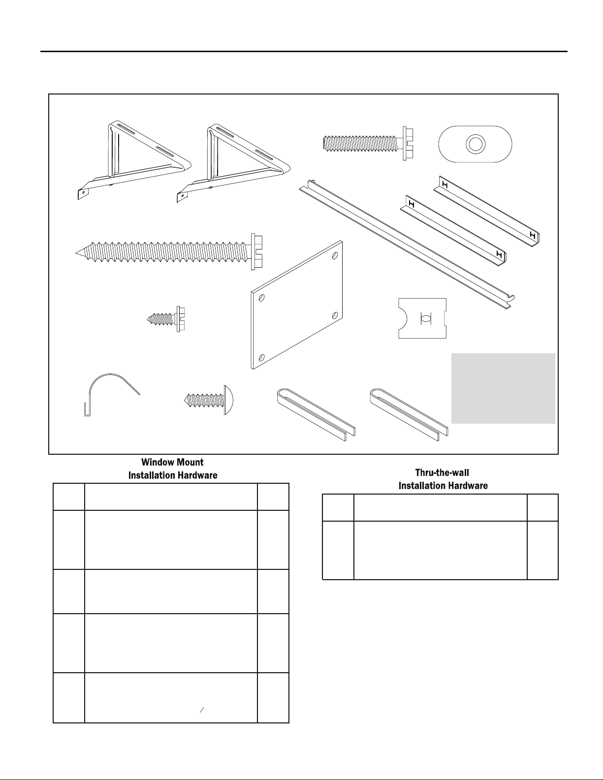
INSTALLATION HARDWARE AND ACCESSORY DETAIL
ITEM 10
ITEMS NOT TO SCALE
ITEM 4
ITEM 7
ITEM 1
ITEM 11
ITEM 2
ITEM 5 ITEM 6
ITEM 8
ITEM 12 ITEM 13
ITEM 3
ITEM 9
ITEM 14
FRR009
ITEM
DESCRIPTION QTY.
NO
WINGBOARD MOUNTING PARTS
10 WINGBOARD CLIP (SPRING STEEL) 4
11 SCREW, #8 x ½" PHILLIPS TRUSS HD. 4
WINDOW SEALING
12 WINDOW SEAL GASKET (DARK FOAM) 1
13 CHASSIS SEAL GASKET (LIGHT FOAM) 1
SHELL MOUNTING PARTS
1
2 SCREW, 10-24 x 1" HEX HEAD
3
4 SCREW, SHEET METAL #12 x 2" 7
WINGBOARD ANGLE MOUNTING
5
6 WINGBOARD ANGLE, SIDE 2
7 SCREW, SHEET METAL #8 x
24
3
8
" 2
ITEM
DESCRIPTION QTY.
NO
1WINGBOARD (MASONITE)
4"J" TYPE SPEED NUT
NOTE: K ühl + models do not come w i t h window mou nting
2SUPPORT BRACKET
4
410-24 FLAT WELD NUT
1WINGBOARD ANGLE, TOP
MOUNTING PARTS
4
SCREW, SHEET METAL #12A x 2”
CHASSIS SEAL GASKET (LIGHT FOAM)
14
components. When mounting a cooling and heating model
a window installation kit must be purchased separately.
KWIKS – For all ES and YS models.
KW
IKM – For all EM and YM models.
KWIKL – For all EL and YL models.
7
1
Page 25
Standard Window Installation
Figure 16
NOTE: Hardware and accessories used during installation are shown
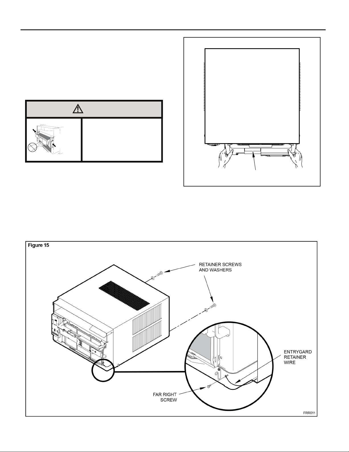
STEP 1. Remove the chassis Entrygard retainer by removing the far
on page 23. Each part will be referred as Item No.
right screw (See Figure 15), save this screw to reattach the
chassis retainer after installation (Step 12). Also, remove and
discard the two retainer screws and washers located at the
rear of the unit (See Figure 15).
CAUTION
Handle Use
Use Handle
Locations
(both sides)
STEP 2. Hold the cabinet stationary, then use the hand grips on both
STEP 3. Remove the large white foam blocks used to restrain the
ends of the control unit support bracket to pull the chassis out
of the cabinet (See Figure 16).
compressor during shipment (See Figure 17). Inspect base
pan for dislodged white foam blocks and remove. Do not
remove any other foam parts.
Use handle on both sides to
pull unit from sleeve.
Do not push, pull or lift from
center of support.
CONTROL UNIT
SUPPORT BRACKET
STEP 4. Anchor the side angles (Item 6) by engaging the tabs of the
l
ower sill plate (See Figure 18, Detail B-2) with the loops of the
side angle. Engage the tabs of the top angle (Item 5) with the
top loops of the side angle (See Figure 18, Detail B-1). Install
two (2) screws (Item 7) to secure the top angle tabs and the
side angle to the cabinet (See Figure 18, Detail B-1).
FRR012
25
Page 26

CAUTION
TOP VIEW OF UNIT
Remove Shipping Blocks
Prior to operating the unit remove
the foam shipping blocks.
Failure to do so may result in
damage to the unit which is not
covered by the manufacturer’s
warranty!
STEP 5. Check the window sill and frame to be sure they are in good
STEP 6. CABINET MOUNTING – Raise the lower window 1/4" more
STEP 7. OUTSIDE SUPPORT MOUNTING – Refer to Figures 20 and
Figure 17
than the height of the cabinet. Carefully slide the cabinet
through the opening until the lower sill plate channel rests
behind the window sill and the top angle rests against the
window (See Figure 19). Center the cabinet within the
opening. Drill three (3) 5/32" diameter pilot holes into window
sill using the holes in the cabinet sill plate as a guide. Install
t
hree (3) #12 x 2" long screws (Item 4) (See Figure 19).
21. Assemble the support brackets (Item 1) to the bottom of
the cabinet with four (4) 10-24 1” long screws (Item 2) and four
combination of the elongated holes of the bracket and different
hole locations in the cabinet, to bring the bottom support bracket
pads in contact with the wall. A 1" x 4" or 2" x 4" SPACER
SHOULD BE USED BETWEEN THE WALL AND SUPPORT
THE BRACKETS WHEN INSTALLED ON ALUMINUM OR
VINYL SIDING. Drill 5/32" diameter pilot holes and secure
the brackets to the wall with two (2) 12A x 2" long screws
(Item 4).
NOTE: DO NOT LEVEL the cabinet from front to back. Make sure there
Adjust the support brackets to provide an inside-to-outside slope for excess
condensation drainage (Refer to Standard Window Installation, Figures 20
through 24). Tighten all screws.
Alternate support method A: If you have a wide window sill which prevents
you from mounting the b
U
set the placement of the
Tighten all screws.
Alternate support method B: If the window ledge gap is narrow, try the
as shown in Figure 24. Bend the short piece so it will be vertical when
installed. Adjust the placement as required. Tighten all screws.
STEP 8.
is approximately 3/8” to 1/2” slope (1/8 to 1/4 bubble on level)
toward the outside of the house.
sing the elongated holes and different hole locations in the cabinet,
between t
Make sure you include the depth of the window channel.
rackets as shown in Figure 23, try the following:
bracket to support the unit’s weight (Figure 23).
he window side channels and cabinet. (Figure 25).
NOTICE
For YOUR security and safety, YOU must
provide a means of preventing the upper
part of the window from opening.
STEP 9. t "J" eht no hsup ,slenap draobgniw eht elbmessa oT ype speed
nuts (Item 9) and spring steel clips (Item 10) (See Figures 26)
on page 31. Secure each panel with two (2) screws (Item 11).
26
LEFT SIDE
REMOVE AND DISCARD
FOAM BLOCKS
COMPRESSOR
BACK
FAN MOTOR
EVAPORATOR COIL
FRONT
REMOVE AND DISCARD
SCREWS
RIGHT SIDE
REMOVE AND SAVE
SCREW FOR
RE-INSTALLATION
FRR045
Page 27

27
Page 28
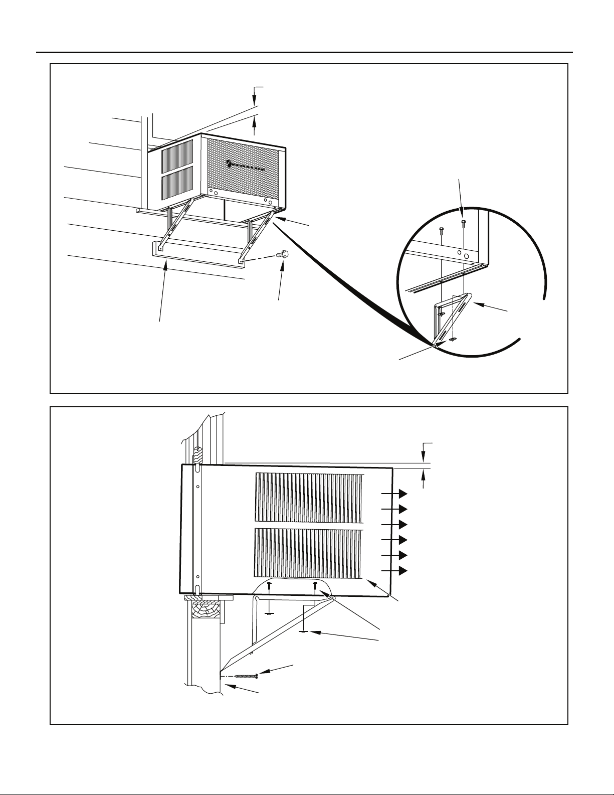
Figure 20
3/8” SLOPE DOWN
#10-24 x 1” HEX HD.
SCREW (ITEM 2)
SUPPORT BRACKET
(ITEM 1)
SPACER SHOULD BE USED BETWEEN
WALL AND BRACKET WHEN INSTALLED
ON ALUMINUM OR VINYL SIDING.
Figure 21
#12 x 2” SCREW
(ITEM 4)
SUPPORT
BRACKET
(ITEM 1)
10-24 x FLAT WELD
NUT (ITEM 3)
FRR015
3/8” SLOPE DOWN
CONDENSER
AIR OUTLET
28
CONDENSER
AIR INLETS
#10-24 SCREW
#10-24 FLAT WELD NUT
#12 x 2” SHEET METAL
SCREW (ITEM 4)
SPACER SHOULD BE USED BETWEEN
WALL AND BRACKET WHEN INSTALLED
ON ALUMINUM OR VINYL SIDING.
FRR016
Page 29

Figure 22
STONE LEDGE
3/8” SLOPE DOWN
CONDENSER
AIR INLETS
#10-24 SCREW
#10-24 FLAT WELD NUT
#12 x 2” SHEET METAL
SCREW (ITEM 4)
SPACER
FRR017
Figure 23
3/8” SLOPE DOWN
#10-24 SCREW
STRAIGHTEN TAB TO LAY FLAT
ALONG THE BOTTOM RAIL OF
THE SHELL
#10-24 FLAT WELD NUT
SECURE THE LONGEST SIDE OF
THE BRACKET TO THE SHELL
ADJUST IN OR OUT TO REST
ON THE LEDGE
STONE LEDGE
FRR018
29
Page 30

Figure 24
3/8” SLOPE DOWN
#10-24 SCREW
#10-24 FLAT WELD NUT
STONE LEDGE
OUTSIDE WALL
DIMENSION “A”
CUT
HERE
DISCARD
SHADED AREA
CUT TO FIT DIMENSION “A”
AND BEND DOWN TO FORM
A VERTICAL LEG.
A
FRR019
30
Page 31

STEP 10. INSTALL THE R1 INSULATION PANEL – To
minimize air leaks and ensure optimal insulation, install the
included R1 insulation panel. (14 in parts list) (See Figure 28
A-C).
First, measure the width from one side of the cabinet/sleeve
(covering the side angles where the wingboard was just
secured) to the end of the wingboard. (See Figure 28A)
Next cut the R1 insulation panel to the measured width and
remove protective cover, exposing adhesive on back panel
(See Figure 28B)
Last, evenly apply the adhesive side of the panel across the
entire height and width from side angle to wingboard panel.
(See Figure 28C)
Repeat the steps above for the other wingboard panel.
STEP 11. INSTALL THE WINDOW SEALING GASKETS – Measure
and cut the dark foam window seal gasket (Item 12) and
install it between the upper glass panel and the top part of
the window sash (Figure 29).
CAUTION
Cut/Sever
Although great care has been
taken to minimize sharp edges
in the construction of your unit,
use gloves or other hand
protection when handling unit
Failure to do so can result in minor
to moderate personal injury.
STEP 12. Carefully team lift the chassis and set it into the cabinet. Slide
the chassis stopping approximately 3" from full insertion. Insert
the chassis seal gasket (Item 13) one inch deep between the
chassis and
33.
inserting the gasket at either bottom corner and go up the
side, across the top, and down the opposite side. Then push
the chassis all the way into the cabinet.
the cabinet (See Figure 31) as shown on page
A paint stir stick or ruler might be helpful here. Begin
Figure 26
CAUTION
Excessive Weight Hazard
Use two or more people when
installing your air conditioner.
Failure to do so can result in
back or other injury.
“J” TYPE SPEED NUT
(ITEM #9) 2 REQUIRED
CUT
WINGBOARD
PANEL
NOTE: If the chassis seal gasket is not installed or installed improperly,
the operation of the unit will be negatively affected. Operational
STEP 13. Reattach the entry guard chassis entry guard retainer wire with
the same screw retained in Step 1 (See Figure 15).
SPRING STEEL
CLIP (ITEM 10)
2 REQUIRED
3"
CUT EDGE
CENTER THE HOLE IN THE
SPEED NUT OVER THE SLOT
IN THE WINGBOARD PANEL
3"
SLIDE CLIP OVER CUT EDGE
OF WINGBOARD PANEL
ROTATED 90°
FRR021
31
Page 32

Figure 27
TOP OF CABINET
PLACE WINGBOARD PANEL IN WINDOW JAM
TO COMPRESS THE SPRINGS INSIDE THE
RUNNERS, AND SWING THE WINGBOARD
PANELS INTO PLACE AS INDICATED BY THE
DASHED LINES.
Figure28
INSERT FOAM WINDOW
SEAL GASKET (ITEM 12)
WINDOW JAM
CLIP (ITEM 10)
SECTION A-A
A
A
I
C
SECURE THE SIDE WINGBOARD PANELS TO
THE SIDE ANGLES WITH FOUR (4) #8 x 1/2” LONG
SCREWS (ITEM 11), TWO ON EACH SIDE.
32
FRR022
SECTION B-B
Page 33

OPTIONAL: e ti taht os droc ylppus eht selbmessa yrotcaf ehT xits the left
side of the unit at the bottom. At the consumer’s discretion,
the supply cord can be routed to exit the right side of the unit.
To do this, route the supply cord to the right side. Pull the
supply cord taunt through the loops (Refer to Cord Routing
Change, Figure 31) and route the cord down.
Use Tool Provided
Please use the provided tool to attach the decorative front to the chassis.
Figure 29
STEP 14.
To attach and prevent damage to the front grille align the
cord notch over the cord and center the fresh air lever, then
align and tighten the four (4) captive screws as indicated by
the arrows in Figure 29. Before closing the front panel, be
sure the filter is in place. Make sure curtains do not block
the side air intakes.
STEP 15. Refer
to the Control Panel Operation section for instructions.
STEP 16. You are now ready to control the comfort level of the room.
USE HAND TOOLS
DO NOT O VER T IGHTE N
B
LOCATION OF GRILLE
REMOVAL TOOL
FRR053
33
Page 34

34
Page 35

35
Page 36

Through-the-Wall Installation
The following instructions apply to wood, masonry, brick, concrete or cinder
block wall construction.
STEP 1. Follow steps 1, 2, 3, and 4 of the "STANDARD WINDOW
STEP 2. CABINET PREPARATION – Remove the sill plate
INSTALLATION" instructions beginning on page 25.
from the
cabinet by removing two (4) nuts and screws (Figure 39).
Note that the chassis retainer is secured by a right side nut
and screw (Detail A, Figure 39). Bend the tabs of the sill plate
down into its channel at both ends of the plate or cut them off
(Detail B, Figure 39) Rotate the sill plate 180° (end-to-end,
Detail B, Figure 39) and reinstall. Reverse the orientation of
the nuts and screws, so that the head of the screws are on the
underside of cabinet facing up
C, Figure 39). Ensure that the chassis retainer is reinstalled
as shown in the detail.
and the nuts are on top (Detail
NOTICE
The outside cabinet condenser air intake louvers
MUST NOT BE BLOCKED by extra thick walls.
STEP 3. WALL PREPARATION – The maximum wall thickness
permissible without special construction is determined by
the model size to be installed. Observe the maximum wall
thickness shown in Figure 40. Walls exceeding the maximum
thickness shown in the chart, should be altered as shown in
Figure 40.
B
Table 3
FINISHED
DIMENSION
A 16 3⁄16" 18 3⁄16" 20 3⁄8"
B 26
SMALL
CHASSIS
3
⁄16" 26 3⁄16" 28 1⁄4"
MEDIUM
CHASSIS
size.
A
LARGE
CHASSIS
STEP 4. CHECKING WIRING AND PLUMBING – Check for wiring and
STEP 5. OPENING CONSTRUCTION – Depending upon size of unit
plumbing inside and outside of the wall to be sure none will be
damaged when the
to be installed, lay out the hole dimensions per Table 3. Cut
construction is typical frame or 2” x 4” studding with brick or
stone veneers, locate the opening next to one of the studs.
For masonry, concrete or cinder block walls, locate opening
for your convenience (See Figures 41, 42, and 43).
cabinet framework is being constructed.
36
Page 37

37
Page 38

38
Page 39

STEP 6. Slide the cabinet into the hole far enough to allow the
guide-channel of the sill plate to contact the inside wall surface
(Figure 21).
STEP 7. Drill three (3) 5/32” diameter pilot holes (use the sill-plate holes
as a guide) into the frame and install three (3) #12 x 2" long
screws (Item 4) (Figure 21).
NOTE: Alternate fasteners are required when securing the sill plate or
support brackets to material other than wood (cinde
r block, brick,
masonry or concrete). These items can be purchased at your
local hardware store.
NOTE: DO NOT LEVEL the cabinet from front to back. Make sure there
is approximately 3/8” to 1/2” slope (1/8 to 1/4 bubble on the level)
toward the outside of the house.
STEP 8. Drill two (2) 5/32" diameter pilot holes in each cabinet side
at the locations shown (Figure 21) and install four (4) #12 x
2" screws (Item 4). Provided
that Step 5 (hole construction)
provides a sturdy mount with solid vertical studs, support
brackets may not be required. The installation must support
the weight of the unit plus an additional weight of 400 pounds
on the rear of the cabinet. If support brackets (Item 1) are
available, they can be installed as shown in Figure 21.
EXPANSION ANCHOR BOLT
MOLLY OR TOGGLE BOLT
Figure 44
TRIM MOULDING
SCREW #12 x 2"
LONG (USE 3)
(ITEM 4)
SILL PLATE GUIDE CHANNEL
STEP 9. Complete the installation by following steps 12 through 15
of “STANDARD WINDOW INSTALLATION” ins
tru ctions,
page 25.
CAULK ALL SIDES WEATHER TIGHT
INSIDE AND OUTSIDE
3/8" SLOPE DOWN
3"
4"
NOTE: SUPPORT BRACKET MAY BE
OMITTED FROM THROUGH-THE-WALL
INSTALLATIONS IF THE CABINET IS
SECURED AS FOLLOWS. DRILL TWO
HOLES IN EACH SIDE AND INSTALL 4
FASTENERS (2 EACH SIDE). USE #12 x 2"
SCREWS, (ITEM 4).
TOGGLE BOLTS OR EXPANSION BOLTS
MAY BE REQUIRED.
CABINET
INSIDE WALL SURFACE
SUPPORT BRACKETS
SCREW #12 x 2" LONG
DRILL 5/32" DIA. PILOT HOLES.
FRR031
39
Page 40

Final Inspection & Start-up Checklist
Inspect and ensure that all components and accessories have been
installed properly and that they have not been damaged during the
installation progress.
Check the condensate water drain(s) to ensure that they are adequate
for the removal of condensate water, and that they meet the approval
of the end user.
Ensure that all installation instructions concerning clearances around
indoor coil, and outdoor coil are free from any obstructions.
Ensure that the circuit breaker(s) or fuse(s) and supply circuit wire
size have been sized correctly. If the unit was supplied with a power
supply cord, insure that it is stored properly.
Ensure that the entire installation is in compliance with all applicable
national and local codes and ordinances having jurisdiction.
Secure components and accessories, such as a decorative front
cover.
Start the unit and check for proper operation of all components in
each mode of operation.
Instruct the owner or operator of the units operation, and the
manufacturer's Routine Maintenance.
NOTE: A log for recording the dates of maintenance and/or service is
recommended.
Present the owner or operator of the equipment with the Installation
& Operation Manual, all accessory installation instructions, and the
name, address and telephone number of the Authorized Friedrich
Warranty Service Company in the area for future reference if
necessary.
Heat pumps operate differently
If your unit is a "Y", or heat pump model, there are some things that you
will want to be aware of. Some functions of a heat pump differ from your
unit when it is used for heating:
It is normal for
1. ice to form on the outdoor coil of the heat pump.
Moisture in the outside air, passing over the coil when very cold,
will form ice.
2. If the outdoor temperature drops below 37° F (3° C), your heat
p
ump will automatically turn on the electric resistance heat. When
the temperature rises to 40° F (4° C), the compressor will resume
the heat pump operation. If your unit is a 115 volt model (YS10),
it is designed for use in warmer climates and does not have an
electrical heat feature, and will not provide adequate heat below
37° F (2.8° C).
Control Panel Battery Change Procedure
Remove the grille, by loosening four (4) captive screws (See Figure 45). In
the upper left corner, remove one (1) screw on the battery retaining door
(See Figure 46). Remove and replace the battery (CR2450). Reinstall
the battery retaining door. Align the grille guide pins then tighten the four
Clean or replace it as necessary.
Figure 45
This is a warm weather appliance
Your air conditioner is designed to cool in warm weather when the outside
temperature is above 60° F (15.6° C) and below 115° F (46.1° C), so it
cool a room if it is already cool outside. If you want to cool a room in the
spring or fall, select the FAN ONLY
air control to Fresh Air. This will bring in a supply of cooler outside air.
mode and set the Fresh Air/Exhaust
won't
Condensation is normal
Air conditioners actually pump the heat and humidity from your room to the
outside. Humidity becomes water, and your air conditioner will use most
of the water to keep the outside coil cool. If there is excessive humidity,
there may be excess water that will drip outside. This is normal operation.
Frosting
ONLY and the frost will disappear. Setting the thermostat a little warmer
will probably prevent the frosting from recurring.
Noises
All air conditioners make some noise. Friedrich units are designed to
operate as quietly as possible. An air conditioner mounted in a wall is
quieter than one mounted in a window. It is important to ensure that the
chassis seal gasket (Item 13) is properly installed (refer to installation
instructions).
USE HAND TOOLS
DO NOT OVER TIGHTEN
1. USE HAND TOOLS WHEN INSTALLING AND
REMOVING FRONT PANEL.
DO NOT OVERTIGHTEN SCREWS.
2. DISCONNECT POWER AND FOLLOW ALL
LABELED WARNINGS WHEN FRONT PANEL
IS REMOVED.
Figure 46
FRR010
40
Page 41

Routine Maintenance
monthly, and more frequently if conditions warrant. The unit must be turned
To Remove, Wash and Replace Filter
Coils & Chassis
NOTE:
The indoor coil and outdoor coils and base pan should be inspected
periodically (annually or semi-annually) and cleaned of all debris (lint, dirt,
leaves, paper, etc.) as necessary. Under extreme conditions, more frequent
cleaning may be required. Clean the coils and base pan with a soft brush
and compressed air or vacuum. A pressure washer may also be used,
pack when pressure cleaning coils.
Do not use a caustic cleaning agent on coils or base pan..
Use a biodegradable cleaning agent and degreaser. The use
of harsh cleaning materials may lead to deterioration of the
Service and Assistance
Before calling for service, please check the “Troubleshooting Tips” section
avoid unnecessary service calls, and save you the cost of a service call
if the problem is not due to the product itself. If you have checked the
“Basic Troubleshooting” section and still need help, it is available as follows:
our web site at www.friedrich.com.
If you require further assistance
You can call the Customer Support Call Center at 1-800-541-6645.
Before calling, please make sure that you have the complete model and
serial number, and date of purchase of your equipment available. By
providing us with this information, we will be better able to assist you.
Our specialists are able to assist you with:
Referrals to dealers, and distributors.
Use and Care Information.
Recommended maintenance procedures.
Installation information.
Referrals to Authorized Service Providers and Parts depots.
42
43
NOTE: It is extremely important to insure that none of the electrical
and/or electronic parts of the unit get wet. Be sure to cover all
electrical components to protect them from water or spray.
Decorative Front
Use a damp (not wet) cloth when cleaning the control area to prevent
water from entering the unit, and possibly damaging the electronic control.
The decorative front and the cabinet can be cleaned with warm water
and a mi
ld liquid detergent. Do NOT use solvents or hydrocarbon based
cleaners such as acetone, naphtha, gasoline, benzene, etc.
The indoor coil can be vacuumed with a dusting attachment if it appears
to be dirty. DO NOT BEND FINS. The outdoor coil can be gently
sprayed with a hose if you can get to it. If not, you might call your dealer
for a more thorough cleaning when needed.
vacuuming with a dust attachment or by cleaning in the sink using warm
reinstalling. Use caution the coil surface can be sharp.
Fan Motor & Compressor
The fan motor & compressor are permanently lubricated, and require no
additional lubrication.
Wall Sleeve
Inspect the inside of the wall sleeve and drain system periodically (annually
or semi-annually) and clean as required. Under extreme conditions, more
frequent cleaning may be necessary. Clean both of these areas with an
antibacterial and antifungal cleaner. Rins
water and ensure that the drain outlets are operating correctly. Check the
sealant around the sleeve and reseal areas as needed.
e both items thoroughly with
Available Accessories
DC-2 Drain Kit – Part No. 01900235
In some installations, excess condensate water caused by extremely humid
conditions, may result in an undesirable water drip such as on a patio or
over an entryway. MODEL DC-2 DRAIN KIT (Part No. 01900-235) can be
installed to drain excess condensation to an alternate location.
Carbon Filter Kits
The kits vary depending on the chassis size (small, medium, large). Each
KWCFS
KWCFM
KWCFL
FriedrichLink™ Adapter Accessory:
KWIFI - FriedrichLink™ Adapter Accessory for wireless control and
additional programming options
Decorative Color Front Panel Kits:
The kits vary depending on the chassis size (small, medium, large.)
KWBGE(S/M/L)A- S/M/L Decorative Front Cover in Classic Beige
KWBLK(S/M/L)A - S/M/L Decorative Front Cover in Black Onyx
K
WBLU(S/M/L)A - S/M/L Decorative Front Cover in Cobalt Blue
KWPNK(S/M/L)A
KWRED(S/M/L)A
KWWHT(S/M/L)A
Window Installation Kits (Standard in Kühl Models without Heat)
KWIKS – For all ES and YS models.
KWIKM – For all EM and YM models.
KWIKL – For all EL and YL models.
See www.friedrich.com for additional accessories for your unit.
- S/M/L Decorative Front Cover in Pink Diamond
- S/M/L Decorative Front Cover in Deep Red
- S/M/L Decorative Front Cover in Designer White
41
Page 42

Troubleshooting Tips
COMPLAINT CAUSE SOLUTION
Unit does not operate.
Unit Trips Circuit Breaker or Blows Fuses.
LCDI Power Cord Trips (Reset Button Pops Out).
Unit Does Not Cool/Heat Room Sufciently, Or
Cycles On And Off Too Frequently.
● The unit is turned to the off position,
or the thermostat is satised.
● The LCDI power cord is unplugged. ● Plug into a properly grounded 3 prong receptacle.
● The LCDI power cord has tripped
(Reset button has popped out).
● The circuit breaker has tripped or
the supply circuit fuse has blown.
● There has been a local power
failure.
● Other appliances are being used on
the same circuit.
● An extension cord is being used. ● Do NOT use an extension cord with this or any
● The circuit breaker or time-delay
fuse is not of the proper rating.
● The LCDI power cord can trip (Reset
button pops out) due to disturbances
on your power supply line.
● Electrical overload, overheating, or
cord pinching can trip (Reset button
pops out) the LCDI power cord.
NOTE: A damaged power supply cord must be replaced with a new power supply cord obtained
from the product manufacturer and must not be repaired.
● The return/discharge air grille is
blocked.
● Windows or doors to the outside are
open.
● The temperature is not set at a cool
enough/warm enough setting.
● The lter is dirty or obstructed. ● Clean the lter, (See Routine Maintenance), or
● The indoor coil or outdoor coil is
dirty or obstructed.
● There is excessive heat or moisture
(cooking, showers, etc.) in the room.
● The temperature of the room you
are trying to cool is extremely hot.
● Turn the unit to the on position and raise or lower
temperature setting (as appropriate) to call for
operation.
See “Electrical Rating Tables” on pg. 6 for the
proper receptacle type for your unit.
● Press and release RESET (listen for click; Reset
button latches and remains in) to resume operation.
● Reset the circuit breaker, or replace the fuse as
applicable. If the problem continues, contact a
licensed electrician.
● The unit will resume normal operation once power
has been restored.
● The unit requires a dedicated outlet circuit, not
shared with other appliances.
other air conditioner.
● Replace with a circuit breaker or time-delay fuse
of the proper rating. See “Electrical Rating Tables”
on pg. 6 for the proper circuit breaker/fuse rating
for your unit. If the problem continues, contact a
licensed electrician.
● Press and release RESET (listen for click; Reset
button latches and remains in) to resume normal
operation.
● Once the problem has been determined and
corrected, press and release RESET (listen for
click; Reset button latches and remains in) to
resume normal operation.
● Ensure that the return and/or discharge air paths
are not blocked by curtains, blinds, furniture, etc.
● Ensure that all windows and doors are closed.
● Adjust the Temperature control to a cooler or
warmer setting as necessary.
remove obstruction.
● Clean the coils, (See Routine Maintenance), or
remove obstruction.
● Be sure to use exhaust vent fans while cooking
or bathing and, if possible, try not to use heat
producing appliances during the hottest part of the
day.
● Allow additional time for the air conditioner to cool
off a very hot room.
42
Page 43

COMPLAINT CAUSE SOLUTION
Unit Does Not Cool/Heat Room Sufciently, Or
Cycles On And Off Too Frequently (continued).
Unit Runs Too Much.
● The outside temperature is below
60°F (16° C).
● The digital control is set to fan
cycling mode.
● The air conditioner has insufcient
cooling capacity to match the heat
gain of the room.
● The air conditioner has insufcient
heating capacity to match the heat
loss of the room.
● This may be due to an excessive
heat load in the room.
● It may also be due to an improperly
sized unit.
● This may be normal for higher
efciency (EER) air conditioners.
● You may notice that the discharge
air temperature of your new air
conditioner may not seem as cold
as you may be accustomed to from
older units. This does not, however,
indicate a reduction in the cooling
capacity of the unit.
● Do not try to operate your air conditioner in the
cooling mode when the outside temperature is
below 60°F (16° C). The unit will not cool properly,
and the unit may be damaged.
● Since the fan does not circulate the room air
continuously at this setting, the room air does not
mix as well and hot (or cold) spots may result.
Using the continuous fan setting is recommended
to obtain optimum comfort levels.
● Check the cooling capacity of your unit to ensure it
is properly sized for the room in which it is installed.
Room air conditioners are not designed to cool
multiple rooms.
● Check the heating capacity of your unit. Air
conditioners are sized to meet the cooling load,
and heater size is then selected to meet the
heating load. In extreme northern climates, room
air conditioners may not be able to be used as a
primary source of heat.
● If there are heat producing appliances in use in the
room, or if the room is heavily occupied, the unit will
need to run longer to remove the additional heat.
● Be sure to use exhaust vent fans while cooking
or bathing and, if possible, try not to use heat
producing appliances during the hottest part of the
day.
● The use of higher efciency components in your
new air conditioner may result in the unit running
longer than you feel it should. This may be more
apparent, if it replaced an older, less efcient,
model. The actual energy usage, however, will be
signicantly less when compared to older models.
● The energy efciency ratio (EER) and cooling
capacity rating (Btu/h) listed on the unit’s rating
plate are both agency certied.
43
Page 44

Addendum 1
Schedule Table with Energy Saving Values
Period Sun Mon Tues Wed Thur Fri Sat
Start Time 600 Start Time 600 Start Time 600 Start Time 600 Start Time 600 Start Time 600 Start Time 600
System Mode Cool System Mode Cool System Mode Cool System Mode Cool System Mode Cool System Mode Cool System Mode Cool
Fan Mode Auto Fan Mode Auto Fan Mode Auto Fan Mode Auto Fan Mode Auto Fan Mode Auto Fan Mode Auto
1
Fan Speed Low Fan Speed Low Fan Speed Low Fan Speed Low Fan Speed Low Fan Speed Low Fan Speed Low
Set Point Cool 78 Set Point Cool 78 Set Point Cool 78 Set Point Cool 78 Set Point Cool 78 Set Point Cool 78 Set Point Cool 78
Set Point Heat 70 Set Point Heat 70 Set Point Heat 70 Set Point Heat 70 Set Point Heat 70 Set Point Heat 70 Set Point Heat 70
Start Time 800 Start Time 800 Start Time 800 Start Time 800 Start Time 800 Start Time 800 Start Time 800
System Mode Cool System Mode Cool System Mode Cool System Mode Cool System Mode Cool System Mode Cool System Mode Cool
Fan Mode Auto Fan Mode Auto Fan Mode Auto Fan Mode Auto Fan Mode Auto Fan Mode Auto Fan Mode Auto
2
Fan Speed Low Fan Speed Low Fan Speed Low Fan Speed Low Fan Speed Low Fan Speed Low Fan Speed Low
Set Point Cool 85 Set Point Cool 85 Set Point Cool 85 Set Point Cool 85 Set Point Cool 85 Set Point Cool 85 Set Point Cool 85
Set Point Heat 62 Set Point Heat 62 Set Point Heat 62 Set Point Heat 62 Set Point Heat 62 Set Point Heat 62 Set Point Heat 62
Start Time 1800 Start Time 1800 Start Time 1800 Start Time 1800 Start Time 1800 Start Time 1800 Start Time 1800
System Mode Cool System Mode Cool System Mode Cool System Mode Cool System Mode Cool System Mode Cool System Mode Cool
Fan Mode Auto Fan Mode Auto Fan Mode Auto Fan Mode Auto Fan Mode Auto Fan Mode Auto Fan Mode Auto
3
Fan Speed Low Fan Speed Low Fan Speed Low Fan Speed Low Fan Speed Low Fan Speed Low Fan Speed Low
Set Point Cool 78 Set Point Cool 78 Set Point Cool 78 Set Point Cool 78 Set Point Cool 78 Set Point Cool 78 Set Point Cool 78
Set Point Heat 70 Set Point Heat 70 Set Point Heat 70 Set Point Heat 70 Set Point Heat 70 Set Point Heat 70 Set Point Heat 70
Start Time 2200 Start Time 2200 Start Time 2200 Start Time 2200 Start Time 2200 Start Time 2200 Start Time 2200
System Mode Cool System Mode Cool System Mode Cool System Mode Cool System Mode Cool System Mode Cool System Mode Cool
Fan Mode Auto Fan Mode Auto Fan Mode Auto Fan Mode Auto Fan Mode Auto Fan Mode Auto Fan Mode Auto
4
Fan Speed Low Fan Speed L
Set Point Cool 82 Set Point Cool 82 Set Point Cool 82 Set Point Cool 82 Set Point Cool 82 Set Point Cool 82 Set Point Cool 82
Set Point Heat 62 Set Point Heat 62 Set Point Heat 62 Set Point Heat 62 Set Point Heat 62 Set Point Heat 62 Set Point Heat 62
ow Fan Speed Low
Fan Speed Low Fan Speed Low Fan Speed Low Fan Speed Low
Commercial Schedule
Period Sun Mon Tues Wed Thur Fri Sat
Start Time 700 Start Time 700 Start Time 700 Start Time 700 Start Time 700 Start Time 700 Start Time 700
System Mode Cool System Mode Cool System Mode Cool System Mode Cool System Mode Cool System Mode Cool System Mode Cool
Fan Mode Auto Fan Mode Auto Fan Mode Auto Fan Mode Auto Fan Mode Auto Fan Mode Auto Fan Mode Auto
1
Fan Speed Med Fan Speed Med Fan Speed Med Fan Speed Med Fan Speed Med Fan Speed Med Fan Speed Med
Set Point Cool 84 Set Point Cool 75 Set Point Cool 75 Set Point Cool 75 Set Point Cool 75 Set Point Cool 75 Set Point Cool 84
Set Point Heat 62 Set Point Heat 70 Set Point Heat 70 Set Point Heat 70 Set Point Heat 70 Set Point Heat 70 Set Point Heat 62
Start Time 1800 Start Time 1800 Start Time 1800 Start Time 1800 Start Time 1800 Start Time 1800 Start Time 1800
System Mode Cool System Mode Cool System Mode Cool System Mode Cool System Mode Cool System Mode Cool System Mode Cool
Fan Mode Auto Fan Mode Auto Fan Mode Auto Fan Mode Auto Fan Mode Auto Fan Mode Auto Fan Mode Auto
2
Fan Speed Med Fan Speed Med Fan Speed Med Fan Speed Med Fan Speed Med Fan Speed Med Fan Speed Med
Set Point Cool 84 Set Point Cool 84 Set Point Cool 84 Set Point Cool 84 Set Point Cool 84 Set Point Cool 84 Set Point Cool 84
Set Point Heat 62 Set Point Heat 62 Set Point Heat 62 Set Point Heat 62 Set Point Heat 62 Set Point Heat 62 Set Point Heat 62
Residenal Schedule
44
Page 45

Friedrich Air Conditioning Company
10001 Reunion Place, Suite 500
San Antonio, TX 78216
1-800-541-6645
www.friedrich.com
ROOM AIR CONDITIONERS
LIMITED WARRANTY
FIRST YEAR
ANY PART: If any part supplied by FRIEDRICH fails because of a defect in workmanship or material within twelve months from date of original
purchase, FRIEDRICH will repair the product at no charge, provided room air conditioner is reasonably accessible for service. Any additiona
cost for removing inaccessible units and/or charges for mileage related to travel by a Service Agency that exceeds 25 miles one way will be the
responsibility of the owner. This remedy is expressly agreed to be the exclusive remedy within twelve months from the date of the original purchase.
l labor
SECOND THROUGH FIFTH YEAR
SEALED REFRIGERANT SYSTEM: -
in workmanship or material within sixty months from date of purchase, FRIEDRICH will pay a labor allowance and parts necessary to repair the Sealed
Refrigeration System; PROVIDED FRIEDRICH will not pay the cost of diagnosis of the problem, removal, freight charges, and transportation of the air
conditioner to and from the Service Agency, and the reinstallation charges associated with repair of the Sealed Refrigeration System. All su
the sole responsibility of the owner. This remedy is expressly agreed to be the exclusive remedy within sixty months from the date of the original purchase.
APPLICABILITY AND LIMITATIONS: This warranty is applicable only to units retained within the Fifty States of the U.S.A., District of Columbia, and Canada.
This warranty is not applicable to:
1.
2. Products on which the model and serial numbers have been removed.
3. Products which have defects or damage which results from improper installation, wiring, electrical current characteristics, or maintenance; or caused by
ch cost will be
in performance caused by war, government restrictions or restraints, strikes, material shortages beyond the control of FRIEDRICH, or acts of God.
OBTAINING WARRANTY PERFORMANCE: Service will be provided by the FRIEDRICH Authorized Dealer or Service Organization in your area. They are listed
in the Yellow Pages. If assistance is required in obtaining warranty performance, write to: Room Air Conditioner Service Manager, Friedrich Air Conditioning Co.
L
IMITATIONS: THIS WARRANTY IS GIVEN IN LIEU OF ALL OTHER WARRANTIES. Anything in the warranty notwithstanding, ANY IMPLIED WARRANTIES
OF FITNESS FOR PARTICULAR PURPOSE AND/OR MERCHANTABILITY SHALL BE LIMITED TO THE DURATION OF THIS EXPRESS WARRANTY.
MANUFACTURER EXPRESSLY DISCLAIMS AND EXCLUDES ANY LIABILITY FOR CONSEQUENTIAL OR INCIDENTAL DAMAGE FOR BREACH OF
ANY EXPRESSED OR IMPLIED WARRANTY.
NOTE: Some states do not al
damages, so the foregoing exclusions and limitations may not apply to you.
OTHER:
PROOF OF PURCHASE: Owner must provide proof of purchase in order to receive any warranty related services.
All service calls for explaining the operation of this product will be the sole responsibility of the consumer.
All warranty service must be provided by an Authorized FRIEDRICH Service Agency, unless authorized by FRIEDRICH prior to repairs being made.
low limitations on how long an implied warranty lasts, or do not allow the limitation or exclusion of consequential or incidental
45
Page 46

Friedrich Air Conditioning Co.
10001 Reunion Place, Suite 500 • San Antonio, Texas 78216
1-800-541-6645
www.friedrich.com
Printed in Mexico
93001004_03
Page 47

Page 48

Page 49

Aire Acondicionado de Habitación
Manual de Instalación y Operación
Standard Chassis Models
93001004_03
115-Volt:
208-230-Volt:
115-Volt:
208-230-Volt:
SS08, SS10, SS12, SS14, SM15
SS12, SS16, SM18, SM21, SM24
SL22, SL24, SL28, SL36
YS10
ES12, ES16, YS12, EM18
YM18, EM24, EL36, YL24
Page 50

Felicidades!
Gracias por su decisión de comprar el Aire Acondicionado de Alta Eficiencia Friedrich. Su nuevo Friedrich ha sido cuidadosamente diseñado y fabricado para
darle muchos años de funcionamiento confiable y eficiente, manteniendo una temperatura y nivel de humedad confortables. Se han incorporado muchas
características adicionales a la unidad para garantizar un funcionamiento silencioso, la mayor circulación de aire frío y seco, y el funcionamiento más económico.
GRACIAS, a nombre de toda nuestra empresa,
por hacer una compra tan inteligente.
AIR CONDITIONING CO.
SAN ANTONIO, TEXAS
ASSEMBLED IN MEXICO
Registre su aire acondicionado
La información del modelo se puede encontrar en la placa de identificación detrás de la
tapa frontal.
Favor de llenar y enviar la tarjeta de registro
proporcionada con este producto, o
registrarse en línea en www.friedrich.com.
Para su futura comodidad, registre la
información del modelo aquí.
NÚMERO DE MODELO
NÚMERO DE SERIE
MODEL NUMBER
HEATING
REFRIGERANT
XXXXXXXXX
XXXXXXXXXX
VOLTS 115
COOLING
YS10M10A
60 HZ / 1 PH
BTH/HR 6500
SERIAL NUMBER
VOLTS MIN 108
EER 12.0
LICY00008
AMPS 8.0
FUSE PROTECTED
U
L
30.1 OZ R410A
600 PSIG HS
300 PSIG LS
X XX
XXXXXXXXX
CIRCUITS USE 15A
XXXXX
XXXXXXXXXX
TIME DELAY FUSE
XXXXXXXXXX
XXXXXXXXXX
AIR CONDITIONING CO.
SAN ANTONIO, TEXAS
ASSEMBLED IN MEXICO
MODEL NUMBER
YS10M10A
SERIAL NUMBER
LICY00008
FECHA DE COMPRA
BTH/HR 6500
EER 10.4
AMPS 7.0
2
Page 51

Contenido
Medidas de Seguridad...............................................................................................................................................................................................................4
Instrucciones de Desempacado................................................................................................................................................................................................5
ADVERTENCIA: Antes de Operar Su Unidad...........................................................................................................................................................................6
Limpieza del Filtro Estándar / Instrucciones de Instalación.......................................................................................................................................................7
Instrucciones de Instalación del Filtro de Carbono Premium.....................................................................................................................................................8
Funcionamiento del Panel de Control........................................................................................................................................................................................9
Nuevas Opciones del Control Kühl..........................................................................................................................................................................................10
Instrucciones de Funcionamiento del Panel de Control...........................................................................................................................................................11
Funcionamiento del Control Remoto........................................................................................................................................................................................20
Efectividad del Control Remoto................................................................................................................................................................................................20
Selección y Ajuste del Flujo de Aire.........................................................................................................................................................................................22
Instrucciones de Instalación.....................................................................................................................................................................................................23
Instalación de Ventana Estándar ............................................................................................................................................................................................25
Cambio de Enrutamiento del Cable.........................................................................................................................................................................................34
Instalación a Través de la Pared..............................................................................................................................................................................................36
Inspección Final & Lista de Verificación de Arranque..............................................................................................................................................................40
Mantenimiento de Rutina.........................................................................................................................................................................................................41
Servicio y Asistencia................................................................................................................................................................................................................41
Accesorios Disponibles............................................................................................................................................................................................................41
Consejos Para Solucionar Problemas.....................................................................................................................................................................................42
Anexo 1....................................................................................................................................................................................................................................44
Garantía...................................................................................................................................................................................................................................45
3
Page 52

Medidas de seguridad
Tu seguridad y la de los demás es muy importante.
Hemos proporcionado muchos mensajes de seguridad importantes en este manual y en su electrodoméstico. Siempre lea
y obedezca todos los mensajes de seguridad.
Este es un símbolo de alerta de seguridad.
Este símbolo le advierte de los peligros potenciales que pueden matar o lastimar a usted y a los demás.
Todos los mensajes de seguridad le seguirán al símbolo de alerta de seguridad con la palabra
"ADVERTENCIA" o "PRECAUCIÓN". Estas palabras significan:
ADVERTENCIA
PRECAUCIÓN
Todos los mensajes de seguridad le dirán cuál es el peligro potencial, le dirán cómo reducir el riesgo de lesiones, y le dirán
lo que sucederá si no se siguen las instrucciones.
AVISO
Indica un peligro que, de no evitarse, puede resultar en lesiones personales graves
o en la muerte y en daños al prod
Indica un peligro que, de no evitarse, puede resultar en lesiones personales y en
daños al producto u otros bienes.
Indica que le pueden ocurrir daños a los bienes si no se siguen las instrucciones.
ucto u otros bienes.
ADVERTENCIA
Sistema de enfriamiento
bajo alta presión.
No perforar, calentar, exponer a las llamas o
incinerar.
Únicamente los técnicos certificados en
refrigeración deben reparar este equipo.
Los sistemas R410A funcionan a presiones
más altas que el equipo R22. Se deben
utilizar prácticas adecuadas de servicio y
manejo seguro.
Únicamente utilice los medidores de presión
diseñados para su uso con R410A. No utilice
los medidores de presión estándar R22.
4
Page 53

Instrucciones de desempaquetado
PASO 1. Cortar las 4 cintas del empaquetado.
PASO 2. Retirar las barras separadoras de madera del embalaje.
PASO 3. Retirar las almohadillas superiores de hule espuma.
PASO 4. Lentamente retirar la caja exterior, cuidando no aflojar la carcasa
decorativa.
PASO 5. Deslizar el soporte de hule espuma frontal hacia delante.
PASO 6. Levantar cuidadosamente la caja de la carcasa decorativa del
soporte de hule espuma frontal.
PASO 7. Retirar la carcasa decorativa y colocar con cuidado a un lado.
5
Page 54

ADVERTENCIA: Antes de operar su unidad
ADVERTENCIA
Peligro de Descarga Eléctrica
Asegurarse de que su toma de corriente eléctrica tenga la
misma configuración que el enchufe de su aire acondicionado. Si es diferente, consultar a un Electricista Certificado.
No utilizar adaptadores de enchufe.
No utilizar un cable de extensión.
No quitar la clavija de tierra.
Conectar siempre a una toma de corriente de 3 clavijas con
conexión a tierra.
El incumplimiento de estas instrucciones puede ocasionar
la muerte, un incendio o una descarga eléctrica.
Asegúrese de que el cableado es el adecuado para su
unidad.
Si tiene fusibles, deben ser del tipo de retardo. Antes de instalar o
trasladar esta unidad, asegúrese de que el amperaje del interruptor o
el fusible de retardo no superen el amperaje en el Cuadro 1.
NO utilice un cable de extensión
El cable proporcionado le suministrará la cantidad de energía eléctrica
adecuada a la unidad; puede que un cable de extensión no.
Asegúrese de que la toma de corriente sea compatible
con el enchufe del aire acondicionado proporcionado.
Se debe mantener una conexión a tierra en todo momento. Las tomas de
corriente de dos clavijas se deben remplazar por tomas de corriente con
conexión a tierra por un electricista certificado. La toma de corriente con
ión a tierra debe cumplir con todos los códigos y reglamentos
conex
locales y nacionales. Debe utilizar el enchufe de tres clavijas suministrado con el aire acondicionado. Bajo ninguna circunstancia deberá
quitar la clavija de tierra del enchufe.
Pruebe el cable de alimentación
Todas las unidades de aire acondicionado Friedrich salen de fábrica con
un cable de alimentación equipado con un Interruptor de Detección de
Fugas de Corriente (LCDI, en inglés). El dispositivo LCDI cumple con los
requisitos de UL y NEC para aires acondiciona
cable
Para probar el cable de alimentación:
dos conectados mediante
ADVERTENCIA
No utilizar el dispositivo LCDI como interruptor de
ENCENDIDO/APAGADO.
El incumplimiento de esta precaución puede resultar en descomposturas prematuras de su equipo.
Una vez conectada, la unidad funcionará con normalidad sin necesidad
de reiniciar el disposit
bota o si el cable de alimentación está dañado, debe ser sustituido por
un nuevo cable de alimentación suministrado por el fabricante. Póngase
en contacto con nuestra Línea de Asistencia Técnica al (800) 541-6645.
Para agilizar el servicio, por favor tenga su número de modelo a la
mano.
Tabla 1.
-
MODELO
SS08, SS10
SS12, SS14
YS10, SM15
SS12, SS16
SM18, SM21
SL22
SM24, SL28
ES12, ES16
YS12, SL24
SL36, EM18
EM24, EL36
YM18, YL24
Diagrama 1
ivo LCDI. Si, al probarse, el dispositivo LCDI no se
CAPACIDAD DEL
CIRCUITO O
FUSIBLE DE
RETARDO
AMP VOLT
15 125 5-15R
15 250 6-15R
20 250 6-20R
30 250 6-30R
TOMA DE
CORRIENTE
REQUERIDA
NEMA
NO.
1. Enchufar el cable de alimentación a una toma de
corriente de 3 clavijas con conexión a tierra.
2. Oprimir el botón RESET (Ver Diagrama 1).
3. Oprimir el botón TEST, escuchar el chasquido; el botón
RESET se detona y se bota.
4. Oprimir y soltar el botón RESET (Escuchar el chasquido;
el botón RESET se traba y permanece adentro). El cable
de alimentación está listo para su uso.
6
ADVERTENCIA:
¡PROBAR ANTES DE CADA USO!
1. OPRIMIR EL BOTÓN RESET.
2. ENCHUFAR EL LCDI A LA TOMA DE
CORRIENTE.
3. OPRIMIR EL BOTÓN TEST, EL BOTÓN
RESET SE DEBE BOTAR.
4. PRESIONAR EL BOTÓN RESET PARA
UTILIZAR.
NO UTILIZAR SI LA PRUEBA ANTERIOR
FALLA.
CUANDO LA LUZ VERDE ESTÁ
ENCENDIDA, ¡FUNCIONA
CORRECTAMENTE!
FRR001
Page 55

Limpieza del Filtro Estándar / Instrucciones de Instalación
Jalar para abrir la puerta y quitar el filtro sujetando el
agarre del filtro y empujando el soporte del filtro hacia
arriba y hacia afuera.
Diagrama 2 Diagrama 4
Deslizar el agarre del filtro hacia fuera del filtro como se
muestra en el Diagrama 4.
Asegurarse de que el marco frontal con el filtro de malla
le quede de frente.
Diagrama 3
Jalar y abrir el marco frontal. Limpiar el marco frontal
lavándole el polvo del filtro. Utilizar una solución de jabón
suave de ser necesario. Dejar que se seque el filtro.
Diagrama 5
MANIJA
PASO 4. Instalar el agarre del filtro de vuelta en el filtro deslizán-
dolo dentro del filtro.
NOTA: La manija del filtro se desliza en el marco únicamente en
una dirección. Si la pestaña en el marco obstruye el
deslizamiento de la manija, deslizar la manija de la otra
dirección. No forzar la manija dentro del marco.
PASO 5. Instalar el filtro de vuelta en la unidad Seguir las instruc-
ciones dentro de la puerta frontal
Page 56

Instrucciones de Instalación del Filtro de Carbono Premium
2
3
1
2
3
B
C
D
PASO 1. Retirar el filtro de la unidad como se menciona en las instruc-
ciones en el interior de la puerta del filtro.
PASO 2. Sostener el filtro en la parte superior y deslizar la manija del
filtro como se muestra en el Diagrama 4.
PASO 3. Si ya tiene instalado un filtro de carbono, retirar el filtro sucio
colocando el filtro hacia abajo y abriendo el marco frontal
como se muestra en el Diagrama 6.
NOTA: Asegurarse de que el marco con la malla esté orientado hacia
usted.
Diagrama 6
MARCO FRONTAL CON
FILTRO DE MALLA
PASO 4. Colocar el nuevo filtro de carbono en la parte superior de la
parte trasera del marco del filtro. El filtro de carbono ha sido
cortado en la dimensión correcta y debe encajar dentro de la
estructura como se muestra en el Diagrama 7.
NOTA: El filtro de carbono no es un filtro reutilizable, y necesita ser
remplazado cada tres meses para una eficiencia óptima.
PASO 5. Deslizar la manija del filtro para mantener los marcos juntos y
deslizar el conjunto en la unidad según las instrucciones de la
puerta.
NOTA: La manija del filtro se desliza dentro el marco en una sola
dirección. Si la pestaña evita que el marco se deslice, deslizar
la manija desde la otra dirección. No forzar la manija dentro
del marco.
Diagrama 7
8
FRR051FRR050
Page 57

Funcionamiento del Panel de Control
Diagrama 8
Veamos cómo controlar su aire acondicionado. En el panel de control, justo por encima del botón POWER, hay una pantalla de cristal líquido (LCD, en inglés).
Todos los botones de función del panel de control y los íconos modo se pueden ver en el Diagrama 8.
Encendido – Oprimir el botón para encender el aire acondicionado. El botón de encendido se ilumina para indicar que la unidad está encendida. La luz de fondo
en el interruptor de encendido se atenuará automáticamente al 20% de intensidad después de 15 segundos de inactividad. El control remoto también se puede
utilizar para poner en ENCENDIDO / APAGADO (Ver control remoto).
Pantalla – La pantalla es un LCD de alta eficiencia con una luz de fondo blanca integrada. La luz de fondo tiene una función automática de difuminación de dos
(2) etapas. Después de 15 segundos de inactividad, la pantalla se difumina al 20% de intensidad. Después de un período adicional de 120 segundos, la pantalla
se apaga. Al tocar cualquier botón la pantalla cambia automáticamente a su brillo máximo.
Hay tres botones pulsadores de control en cada lado de la pantalla.
VELOCIDAD DEL
SISTEMA:
Ciclos entre
AUTO, CALOR,
FRÍO o SÓLO
VENTILADOR
(Si viene equipado
SYST EM
MODO DE VENTILADOR:
Deja el ventilador ya sea en:
- Ciclo de forma automática
- Ejecutar de forma continua
VENTILADOR:
Deja la velocidad
del ventilador:
BAJA, MED,
ALTA o AUTO
(Si viene equipado)
TEMPERATURA:
Incremento ARRIBA
TEMPERATURA:
Incremento ABAJO
TEMPORIZADOR / PROGRAMACIÓN
Se pone en ENCENDIDO o APAGADO
VENTANA IR:
No bloquearla
ENCENDIDO / APAGADO:
Pone la unidad en
encendido / apagado
FAN
MODE
FAN
SPEED
AUTO
Cambia automáticamente
entre frío y calor
VELOCIDAD DEL VENTILADOR
Velocidad del ventilador
seleccionada
AUTO SPEED
SET POINT
FRÍO
AUTO FAN
CONTINUOUS
AUTO SPEED
CALOR
AUTO
F
SÓLO
VENTILADOR
TIMER
SCHEDULE
BLOQUEO DE
CONTROL
SET POINT
ROOM TEMP
CHECK
FILTER
$MART
F
C
AM
PM
ON OFF
SCHEDULE
WI-FI ENCENDIDO
(Si viene equipado)
ESPERA
PANTALLA DE 2 DÍGITOS
Muestra Configuración para:
- Punto Establecido (Temperatura)
- Temperatura Ambiente
- Reloj (AM/PM)
PROGRAMACIÓN ENCENDIDA
TEMPORIZADOR ENCENDIDO
VELOCIDAD EN AUTOMÁTICO
Selecciona automáticamente la
mejor velocidad de enfriamiento
del ventilador
FILTRO
Revisar / Limpiar
FUNCIONAMIENTO INTELIGENTE $
(Si viene equipado)
9
Page 58

Nuevas Opciones de Control Kühl
El nuevo Kühl le ofrece una gran variedad de opciones para el control,
la programación y temporización, incluyendo capacidades
inalámbricas. El nuevo Adaptador FriedrichLink™ (se vende por
separado) le permite convenientemente controlar, programar y
supervisar su unidad de aire acondicionado de forma remota desde un
teléfono inteligente o computadora. (El accesorio del Adaptador
FriedrichLink™ está disponible a través de minoristas Friedrich
autorizados o www.friedrich.com. Vea la sección del Adaptador
FriedrichLink™ en www.friedrich.com para obtener más detalles)
Opciones de Programación Pre Programadas:
El control digital de su unidad viene equipado con un temporizador de
24 horas y dos opciones pre programadas de manejo de energía por 7
días.
Temporizador de 24 Horas
El temporizador de 24 horas le permite apagar y encender la unidad en
horarios predeterminados mediante el establecimiento de un horario
de encendido y apagado en el panel de control de la unidad. (Vea la
página 12 para obtener detalles sobre la configuración del
temporizador.)
Manejo de la Energía Pre Programada
Su unidad viene de fábrica con dos (2) ajustes de Manejo de Energía
Pre Programados como se muestra en el Anexo 1 (Cuadro de
Programación Residencial y Comercial).
Las Opciones de Programación del Manejo de Energía son:
1. Programación Residencial – Semana Laboral de 40 Horas
2. Programación Comercial – Semana Laboral de 5 Días
La Programación "Residencial" (Semana Laboral de 40 Horas) tiene
cuatro (4) períodos de tiempo: 06:00, 08:00, 18:00 y 22:00. Esta opción
hará que su unidad Kühl Q eleve temporalmente la temperatura
ambiente a 85°F durante las horas en las que la mayoría de la gente
está en el trabajo, bajándola de nuevo a 78°F antes de que la mayoría
de la gente volverá a casa, y luego elevándola ligeramente a 82°F para
mantener una temperatura cómoda durante la noche.
La Programación "Comercial" (Semana Laboral de 5 Días) tiene dos
(2) períodos de tiempo: 07:00 y 18:00. Esta opción hará que su aire
acondicionado eleve la temperatura a 84°F después de las horas de
trabajo habituales y en fines de semana cuando los espacios
comerciales suelen estar desocupados.
(Vea la Sección de Instrucciones de Funcionamiento del Panel de
Control)
Opciones de Programación Personalizada:
La programación personalizada, con un máximo de cuatro ajustes de
temperatura por día, se pueden subir a la unidad a través de la
interface de la micro USB del aire acondicionado o transmitirse
convenientemente de forma inalámbrica mediante el accesorio del
NUEVO Adaptador FriedrichLink™, lo que simplifica enormemente la
programación de una o varias unidades.
Vea el diagrama 9.
Vea www.friedrich.com para instrucciones completas de
Programación Personalizada.
Diagrama 9
FriedrichLink™ Adaptador
AIR CONDITIONING CO.
SAN ANTONIO, TEXAS
ASSEMBLED IN MEXICO
MODEL NUMBER
HEATING
REFRIGERANT
XXXXXXXXX
XXXXXXXXXX
VOLTS 115
COOLING
YS10M10A
60 HZ / 1 PH
BTH/HR 6500
SERIAL NUMBER
VOLTS MIN 108
EER 12.0
LICY00008
AMPS 8.0
FUSE PROTECTED
U
L
BTH/HR 6500
30.1 OZ R410A
EER 10.4
AMPS 7.0
X XX
600 PSIG HS
XXXXXXXXX
CIRCUITS USE 15A
XXXXX
300 PSIG LS
XXXXXXXXXX
TIME DELAY FUSE
XXXXXXXXXX
XXXXXXXXXX
10
Page 59

Instrucciones de Funcionamiento del Panel de Control
MODO VENTILADOR
SISTEMA - El botón de le permite seleccionar secuencialmente
hasta cuatro modos de funcionamiento:
FRÍO
CALOR No disponible en algunos modelos
SOLO VENTILADOR
SYSTEM
MODO AUTO
- AUTO -
AUTO FAN
AUTO FAN
SET POINT
MODO FRIO
SET POINT
MODO CALOR
F
Cuando está en el modo AUTO-FRÍO o CALOR o SÓLO
FRR105
VENTILADOR, también puede seleccionar MODO VENTILADOR,
VELOCIDAD DEL VENTILADOR, PROGRAMACIÓN DE
TEMPORIZADOR, y El MODO DE SISTEMA no cambia.
MODO VENTILADOR – El botón le permite seleccionar entre los
AUTO FAN
modos y .
FRR204
F
AUTO VENTILADOR (Sin Requerimiento de Enfriamiento)
Cuando está en el modo , el sólo ventilador funciona cuando
FRR103
el sistema requiere que la habitación se enfríe o se caliente. Nota: el
ventilador está apagado (no hay ícono de velocidad del ventilador),
CONTINUOUS
AUTO FAN
AUTO FAN
FAN
MODE
SET POINT
F
FRR112
indicado que no hay instrucción de enfriar o calentar.
AUTO VENTILADOR (Requerimiento de Enfriamiento)
AUTO FAN
SET POINT
F
AUTO FAN
SET POINT
FRR104
El sistema tiene un requerimiento de enfriamiento. El ventilador funciona
F
FRR105
a velocidad media.
VELOCIDAD DEL VENTILADOR – Dependiendo de su modelo, el botón le permite alternar entre cuatro o cinco modos de funcionamiento: BAJA, MEDIA, ALTA y AUTO.
AUTO
AUTO
3 Velocidades 4 Velocidades
Cuando se selecciona el modo de AUTO VENTILADOR de la velocidad del ventilador (modo del SISTEMA AUTO, FRÍO o CALIENTE), la velocidad del ventilador varía automáticamente en función de la diferencia
entre el punto establecido de la unidad en el panel de control y la temperatura ambiente efectiva. Cuando el sistema detecta una gran diferencia entre el punto establecido y la temperatura ambiente efectiva,
aumenta la velocidad del ventilador a ALTA durante un período de tiempo. La velocidad del ventilador disminuye, por pasos, conforme la diferencia de temperatura disminuye. Cuando la temperatura de la habitación
coincide con el punto establecido del sistema, la velocidad del ventilador vuelve a la configuración original.
11
Page 60

CONTINUO
CONTINUOUS
El botón seleccionado durante una ventana definida en ENCENDIDO.
F
F
AUTO FAN
SET POINT
SET POINT
En el modo de ventilador el ventilador funciona todo el tiempo. El
CONTINUOUS
FRR113
sistema periódicamente enfría o calienta el flujo de aire, pero el flujo de air no
para.
Las flechas ARRIBA y ABAJO . Presionando ya sea el botón o
cambía la configuración del sistema (temperatura deseada de la
habitación. Estos botones
también se usan para hacer cambios en los
parámetros del sistema más adelante en este manual.
AUTO FAN
SET POINT
AUTO FAN
SET POINT
F
FRR100
F
FRR123
Se Ilumina el ícono
La función TEMPORIZADOR (opción 1, predeterminada del sistema) le permite
definir la ventana de tiempo del sistema diario de ENCENDIDO y APAGADO.
Por ejemplo, le puede dar la instrucción al sistema de que se ENCIENDA a las
8:15 am y se APAGUE a las 1:30 pm todos los días.
La función PROGRAMACIÓN le permite elegir entre Residencial (opción 2) o
Comercial (opción 3). Las opciones de Residencial y Comercial se describen
posteriormente en este manual.
OTRAS FUNCIONES
Diagrama 10
FRR101
Oprimir una vez equivale a 1 grado de cambio. Mantener oprimido el botón
durante más de 0.6 segundos inicia el cambio rápido de incremento /
decremento del punto establecido.
PROGRAMACIÓN DE TEMPORIZADOR – El botón ... le permite seleccio-
nar la función de TEMPORIZADOR o .
SCHEDULE
El botón seleccionado durante una ventana definida en APAGADO.
Se Ilumina el ícono
12
FRR122
ESTABLECER HORA – Para ajustar la hora de la unidad, mantener oprimidos
los botones de HORA y MIN durante tres segundos (Ver Diagrama 10).
AM
AM
FRR128
Las pantallas de las horas actuales de la unidad. Utilice los botones o
para ajustar la hora. Para cambiar de AM a PM, continúe incrementando
(girando) la pantalla. Oprimir el botón TEMPORIZADOR ESTABLECIDO o
"TIMER SET" (Vea el Diagrama 10) para visualizar los minutos actuales de la
unidad.
Page 61

FRR129
Utilice los botones o para ajustar los minutos. El reloj ya está
fijado a las 11:25 AM. Oprimir el botón TEMPORIZADOR
ESTABLECIDO (Vea el Diagrama 10) para visualizar la configuración del
día de la unidad
Para pasar de grados Fahrenheit (F) a Celsius (C), oprimir los botones
de y durante tres segundos.
Se destellará una "C" durante 5 segundos y luego volverá a una pantalla
normal. Para pasar de F a C, oprimir los botones de o dentro
FRR133
de 5 segundos.
FRR130
Utilice los botones o para ajustar el día (1 a 7). La configuración
del día le corresponde a usted el usuario. Si establece el día de hoy = 1,
y hoy es martes, entonces el Día 1 = martes.
F
AUTO FAN
SET POINT
FRR131
Oprimir el botón de TEMPORIZADOR ESTABLECIDO (Vea el Diagrama
10) para salir y guardar la función de ESTABLECER HORA. El botón
TEMPORIZADOR ESTABLECIDO se debe presionar dentro de 15
segundos. La inactividad del botón durante más de 15 segundos hará
que la pantalla se cancele y volverá a la pantalla de funcionamiento
normal.
Selección de °F – °C
Se destellará una "C" durante 5 segundos y luego volverá a una pantalla
FRR134
normal.
AUTO FAN
SET POINT
C
FRR135
El ícono ºF desaparece y se ilumina el ícono de ºC en la pantalla normal.
Función de DIFUMINACIÓN
Hay tres niveles diferentes de brillo de la pantalla, AUTO, 20% y máximo
(100%). Para cambiar la configuración de DIFUMINACIÓN, oprima el
botón de Encendido durante tres segundos.
AUTO FAN
SET POINT
F
FRR192
El 1 indica una configuración de DIFUMINACIÓN en Automático
(predeterminado de fábrica). Utilice los botones o para cambiar
FRR132
la configuración.
13
Page 62

AUTO FAN
SET POIN
F
T
FRR193
El 2 indica una configuración de DIFUMINACIÓN de 20%. Oprimir el
botón TEMPORIZADOR ESTABLECIDO dentro de 15 segundos para
guardar la configuración. La inactividad del botón durante más de 15
segundos hará que la pantalla se cancele y volverá a la pantalla de
funcionamiento normal.
FRR194
El 3 indica una configuración de DIFUMINACIÓN de 100% (brillo
máximo). Oprimir el botón TEMPORIZADOR ESTABLECIDO (Vea el
Diagrama 10) dentro de 15 segundos para guardar la configuración. La
inactividad del botón durante más de 15 segundos hará que la pantalla
se cancele y volverá a la pantalla de funcionamiento normal.
Alertas
Cuando el filtro necesita ser limpiado o reemplazado, aparece el ícono.
CHECK
FILT ER
FRR120
Esto significa que se requiere de un compresor, pero el sistema no está
listo para que el compresor funcione. Por ejemplo, un corte de energía
corto, el compresor no se reiniciará hasta que las presiones internas del
compresor estén en el nivel adecuado.
Bloqueo del Panel de Control
Para bloquear los controles del panel frontal, oprima y mantenga oprimidos los
FAN
botones + durante 3 segundos. El ícono de bloqueo se ilumina para
SPEED
indicar el estado de bloqueo.
AUTO FAN
SET POINT
Para desbloquear, oprima y mantenga oprimidos los botones de +
F
16
FRR1
FAN
SPEED
durante 3 segundos.
AUTO FAN
SET POINT
FILTER
La
alerta puede ser eliminada oprimiendo el botón y durante
F
FRR118
FAN
MODE
3 segundos.
El icono de espera se ilumina cuando el compresor 3 minutos de
tiempo de retraso está activo.
14
AUTO FAN
F
SET POINT
FRR117
El ícono de bloqueo desaparece para indicar el estado de desbloqueo.
Page 63

Estado de Control Externo
$MART
El ícono se ilumina para indicar que el sistema está siendo controlado
de forma remota desde una fuente tal como una red inteligente.
3. Programación Comercial (Selección #2) – Cuando se seleccio-
na, la unidad sigue un conjunto de parámetros de funcionamiento pre programados que abarcan los 7 días de la
semana con 2 ventanas de tiempo durante cada día. Cada
ventana de tiempo tiene su propio conjunto de 6
parámetros de funcionamiento. Consulte el Anexo 1.
AUTO FAN
79
SET POINT
AUTO FAN
79
SET POINT
El ícono se ilumina para indicar que el sistema está recibiendo una conexión
Wi-Fi.
FUNCIONES AVANZADAS
Permítame poner en palabras simples muchas de las funciones avanzadas de su
unidad (el Menú de Temporizador, Programación, Modo de Error, Modo de Prueba,
y Mantenimiento). Las funciones mencionadas en la siguiente sección pueden o no
estar disponibles dependiendo del modelo de aire acondicionado.
Seleccionar Temporizador / Programación
F
$MART
FRR125
F
FRR126
1
Para cambiar la selección , oprimir y mantenga oprimido el botón
TEMPORIZADOR / PROGRAMACIÓN durante 3 segundos.
Si la función de Programación está disponible, el sistema muestra el
ícono + . La pantalla indica que la función de programación
que está activa. Para cambiar a una programación alterna (2 o 3), oprima
el botón o . Si la función de Programación no está disponible,
el ícono Temporizador aparece sin el ícono .
Para guardar y salir de esta selección, oprima el botón TEMPORIZADOR
ESTABLECIDO por 3 segundos (Diagrama 10).
Si no hay actividad del botón durante 15 segundos, la función se
cancelará y se saldrá de la selección original. Una vez que la selección
se guarda o se cancela, la pantalla regresa a la pantalla normal.
SCHEDULE
2
SCHEDULE
FRR137
SCHEDULE
SCHEDULE
AUTO FAN
79
SET POINT
El sistema de control tiene tres funciones de Temporizador /
Programación:
1. Temporizador (predefinido de fábrica) – Le permite dar
instrucciones a la unidad de ENCENDIDO y APAGADO a la
hora programada dentro de una ventana de 7 días. Las
configuraciones de arranque, detenimiento y la ventana del
día se pueden encontrar posteriormente en este manual.
2. Programación Residencial (Selección #1) – Cuando se
selecciona, la unidad sigue un conjunto de parámetros de
funcionamiento pre programados que abarcan los 7 días de la
semana con 4 ventanas de tiempo durante cada día. Cada
ventana de tiempo tiene su propio conjunto de 6 parámetros
de funciona miento. Consulte el Anexo 1. Para hacer un
cambio a las 28 ventanas de tiempo, consulte la sección de
Programación Avanzada de este manual.
F
FRR136
FRR138
Después
el botón durante 3 segundos, la pantalla indica un cambio al
Temporizador/Programador 2. Para guardar y salir de esta selección,
oprima el botón TEMPORIZADOR ESTABLECIDO (Diagrama 10).
de pulsar el botón o , dentro de 15 segundos de oprimir
AUTO FAN
79
SET POINT
La pantalla regresa a la pantalla normal.
F
FRR136
15
Page 64

AUTO FAN
FRR146
79
SET POINT
F
Para activar el marcador de tiempo o el horario seleccionado,
presione y suelte el botón y el sistema seleccionado funcionará en el
modo (1, 2 o 3).
Modificar la función de TEMPORIZADOR
Hora de Inicio del Temporizador
AUTO FAN
79
SET POINT
La pantalla muestra un sistema normal. Oprima y mantenga oprimido el
botón HORA (Diagrama 10) por 3 segundos. Nótese que las horas de
arranque y detenimiento del temporizador se pueden establecer aún
cuando el sistema está en temporizador o en el modo de Programación.
4
F
AM
ON
FRR139
FRR140
FRR143
La pantalla regresa a la normalidad una vez que se guarda la configuración.
Hora de Detenimiento del Temporizador
AUTO FAN
79
SET POINT
La pantalla muestra un sistema normal. Oprima y mantenga oprimido el
botón MIN (Diagrama 10) por 3 segundos. Nótese que las horas de
arranque y detenimiento del temporizador se pueden establecer aún
cuando el sistema está en el modo de Programación.
11
F
FRR144
AM
OFF
FRR141
Utilice el botón o para ajustar la hora. Oprima el botón TEMPORIZADOR ESTABLECIDO (Diagrama 10) para ajustar los minutos.
21
Use the or button to adjust the minutes. Press the TIMER SET
button (Figure 10) within 15 seconds to exit and save the setting. The timer
is now set to start at 4:21 AM.
16
ON
FRR142
FRR145
Utilice el botón o para ajustar la hora. Oprima el botón TEMPORIZADOR ESTABLECIDO (Diagrama 10) para ajustar los minutos.
55
Utilice el botón o para ajustar los minutos. Oprima el botón
TEMPORIZADOR ESTABLECIDO (Diagrama 10) dentro de 15 segundos
para salir y guardar la configuración. El temporizador ahora está configurado para detenerse a las 11:55 AM.
OFF
Page 65

FRR148
SET POINT
F
AUTO FAN
79
SCHEDULE
FRR149
Escenarios de Programación en ENCENDIDO
AUTO FAN
79
SET POINT
La pantalla regresa a la normalidad una vez que se guarda la configuración.
Temporizador – Bloqueo del Control de Programación
AUTO FAN
79
SET POINT
Si la unidad está funcionando en el modo de TEMPORIZADOR o el
PROGRAMACIÓN, y luego oprime cualquier botón excepto el botón
el ícono del Temporizador comienza a parpadear. Todas las
acciones del botón quedan bloqueadas.
deja de parpadear después de 3 segundos.
F
FRR147
F
SCHEDULE
El ícono del Temporizador
AUTO FAN
79
SET POINT
La pantalla muestra un sistema normal.
Si la función de Programación se ENCIENDE durante el funcionamiento
los íconos de y temporizador se iluminan.
normal
trol ejecuta de inmediato los parámetros de progra
de con
período actual.
SCHEDULE
F
FRR154
El sistema
mación del
SCHEDULE
FRR153
AUTO FAN
79
SET POINT
Debe APAGAR el modo de Temporizador o Programación activo
antes de hacer cambios. Una vez realizados los cambios, oprima el
botón para reactivar el modo de Temporizador o Programación.
El temporizador o el modo de programación seran reactivados.
F
FRR150
17
Page 66

Escenarios de Temporizador en ENCENDIDO
Escenario #1
AUTO FAN
79
SET POINT
La pantalla muestra operando un sistema normal.
AUTO FAN
79
F
Si la función de temporizador se ENCIENDE durante la hora de ENCENDIDO, el ícono de temporizador se ilumina. El sistema de control sigue
funcionando.
FRR156
Escenarios de Programación en APAGADO
Escenario #1
SET POINT
F
FRR159
FRR157
Si la función de temporizador se ENCIENDE durante la hora de APAGADO, el ícono de se ilumina. El sistema de control inmediatamente
APAGA la unidad.
Escenario #2
AUTO FAN
79
SET POINT
La pantalla muestra operando un sistema normal.
F
FRR158
AUTO FAN
79
SET POINT
La pantalla muestra la unidad en el modo de Programación.
AUTO FAN
79
SET POINT
Si la función de programación se APAGA durante un estado activo de
programación (no apagado), los íconos de Temporizador y se
apagan. El control permanece en el estado actual. La pantalla muestra
un sistema normal operando.
Escenario #2
F
SCHEDULE
FRR160
F
FRR161
SCHEDULE
18
SCHEDULE
FRR162
La pantalla muestra la unidad en modo de Programación durante un
período inactivo (APAGADO).
Page 67

AUTO FAN
F
AUTO FAN
F
79
SET POINT
FRR163
Si la función de Programación se APAGA durante un periodo inactivo
(APAGADO), los íconos de Temporizador y se apagan.
La unidad se despierta en el último estado conocido sin programar.
Escenarios del Temporizador en APAGADO
La pantalla muestra la unidad en el modo de Temporizador durante un
período inactivo (APAGADO).
SCHEDULE
FRR166
79
SET POINT
Si la función de Temporizador se APAGA durante un periodo
(APAGADO), el ícono de temporizador se apaga. La pantalla
muestra un sistema normal.
AUTO FAN
79
SET POINT
Si la función de Temporizador se APAGA durante la hora de ENCENDIDO. El ícono de Temporizador se apaga. El control permanece
en el estado actual.
AUTO FAN
F
F
FRR167
FRR168
79
SET POINT
La pantalla muestra un sistema normal.
FRR169
19
Page 68

Funcionamiento del Control Remoto
Control Remoto – Vea los Diagramas 12 y 13 durante la descripción del
funcionamiento.
Primeros Pasos – Instalar dos (2) baterías AAA en el compartimiento de la
batería en la parte posterior de la unidad.
Operación – El control remoto debe estar dentro de 25 pies del funcionamiento del aire acondicionado. (Vea el Diagrama 11 para la eficacia). Oprimir
el botón de encendido para encender el control remoto. El control remoto se
apagará automáticamente después de 15 segundos si los botones no están
siendo presionados. El control remoto debe estar encendido para controlar la
unidad.
Botón de ENCENDIDO – Enciende y apaga el control remoto y la unidad.
Botón de SISTEMA – Le permite al usuario seleccionar de forma secuencial
lo siguiente: AUTO-AUTO, de FRÍO , CALOR y SÓLO VENTILADOR
Cuando se oprime el botón, la pantalla indica qué modo ha sido seleccionado a través de un mensaje en la pantalla. Nótese que cuando la función de
calefacción no está disponible, el sistema automáticamente se saltará el modo
de CALOR.
Botón de MODO DE VENTILADOR – Selecciona entre el funcionamiento
automático ( ) o En el modo de , el ventilador
únicamente se enciende y se apaga cuando funciona el compresor o la
función de calor está habilitada.
AUTO FAN
NOTA: no está disponible en el Modo de SÓLO VENTILADOR, la
pantalla indica . En el modo de
se determina por su selección con el botón de
AUTO FAN
, la velocidad del ventilador
Botón de VELOCIDAD DEL VENTILADOR – Se utiliza para seleccionar de
forma secuencial la nueva velocidad del ventilador, además del funcionamiento en AUTO. Cuando se oprime el botón , cambia el ícono de
velocidad del ventilador (triángulo) para indicar el nivel de velocidad. La
velocidad del ventilador varía automáticamente en función de la temperatura
establecida en el panel de control y la temperatura real de la habitación. Por
ejemplo, si hay una gran diferencia entre su temperatura establecida y la
temperatura ambiente efectiva, la velocidad del ventilador del sistema se
incrementa a ALTA. Permanece a esta velocidad hasta que la temperatura de
la habitación coincide con la temperatura establecida.
Botón de PROGRAMACIÓN – El botón prende y apaga la función
de programación. Oprima el botón de Programación una vez para encender la
Programación (Residencial, Comercial, Temporizador, o Personalizada) que
ya haya sido seleccionada en la unidad. Al oprimir el botón una
segunda vez apaga la función de programación
Flechas de ARRIBA y ABAJO – Al oprimir los botones de (ARRIBA) o
.... ..(ABAJO) se cambia la temperatura ambiente deseada. Los límites
mínimos y máximos de configuración predeterminados de fábrica son de 60°F
(16°C) y 99ºF (37°C). Estos botones se utilizan también para navegar entre
las opciones de las funciones cuando se utiliza el Menú de Usuario o el Modo
de Mantenimiento.
Efectividad del Control Remoto
Control Remoto de Mano – Tiene rango de funcionamiento de hasta 25
pies. La señal infrarroja del control remoto debe tener una ruta libre para
transmitir la instrucción a la unidad de aire acondicionado. La señal del
control remoto tiene cierta capacidad de "rebotar" en las paredes y muebles
similar a la de un control remoto de televisión. El siguiente diagrama muestra
el rango de funcionamiento normal del control en una habitación estándar
con techos de 8 pies de altura.
20
Page 69

FRR081
Diagrama 12
SISTEMA
SUBIR
TEMPERATURA
VELOCIDAD DEL
VENTILADOR
AUTO
AUTO FAN
CONTINUOUS
AUTO
SYSTEM
FAN SPEED
POWER
F
C
FAN MODE
SCHEDULE
PANTALLA
MODO DE
VENTILADOR
ENCENDER
BAJAR
TEMPERATURA
PROGRAMACIÓN
Diagrama 13
MODO DEL
SISTEMA
MODO DE
VENTILADOR
VELOCIDAD DEL
VENTILADOR
ÍCONO DE
FRÍO
AUTO
AUTO FAN
CONTINUOUS
AUTO
ÍCONO DE
CALOR
ÍCONO DE SÓLO
VENTILADOR
88
F
C
ÍCONO DE
PROGRAMACIÓN
ÍCONOS
DE °F / °C
FRR082
21
Page 70

Selección y Ajuste del Flujo de
Aire
Ajuste de dirección del flujo de aire
La trayectoria del flujo de aire se puede ajustar para distribuir el aire de
forma independiente desde el lado izquierdo o derecho de la abertura de
descarga. Cada una de las hileras de persianas se pueden dirigir a la
izquierda, derecha, arriba o abajo con el fin de lograr el posicionamiento
del flujo de aíre más óptimo.
Para ajustar la dirección del flujo de aire, tomar la palanca en el centro de
la hilera de persianas y moverla en la dirección en la que a usted le
gustaría que el aire se dirija. Tenga en cuenta que es normal que el flujo
de aire pueda ser más fuerte de un lado de las persianas que del otro.
Control del aire fresco y del escape
Diagrama 13
El aire acondicionado tiene la capacidad de atraer aire fresco a la
habitación o extraer el aire mohoso de la habitación. El panel de control
se encuentra en la parte superior de la unidad (Ver Diagrama 14).
PARA ATRAER AIRE FRESCO - Mover la palanca a la posición de Aire
Fresco que permite que el aire exterior entre en la habitación. Esto
es útil en el otoño y la primavera como un medio de atraer el aire fresco
del exterior cuando se utiliza SÓLO VENTILADOR. También se puede
utilizar en el verano con el compresor en el Modo de Refrigeración si lo
desea.
PARA EXTRAE
Extraer Esto permitirá que el aire mohoso pueda ser expulsado al
exterior de la vivienda. Esto es especialmente útil en la primavera u
otoño, cuando el aire interior tiende a ser mohoso, o después de una
reunión social que involucra a fumadores, o para eliminar los malos
olores de la cocina.
MEJOR RENDIMIENTO - Mover la palanca a la Posición de
Re-Circulación . Este es el modo más eficaz para enfriar o calentar.
R EL AIRE INTERIOR - Mover la palanca a la posición de
FRR008
22
Page 71

Instrucciones de instalación
Cuadro 3
DESIGANCIÓN DEL
MODELO
TAMAÑO DE GABINETE
(A X A X D)
CHASSIS PEQUEÑO - SS,
ES, YS
15
"x 25
x 29" (405 mm x
660 mm x 737 mm)
CHASSIS MEDIANAO SM, EM, YM
17
15/16 "
x 25
15/16
" x 29" (455 mm x
660 mm x 737 mm)
CHASSIS GRANDE - SL,
EL, YL
20
3/16
"x 28" x 35
1/2
" (513 mm x
711 mm x 851 mm)
¡LEA ESTO PRIMERO! Requerimientos Eléctricos
ADVERTENCIA
Las siguientes instrucciones son para los grupos de modelos de
chasis estándar que se distinguen por las dos primeras letras de
las designaciones del modelo y los tamaños del gabinete, enlistados en el Cuadro 3.
Peligro de Descarga Eléctrica
Asegurarse de que su enchufe eléctrico tenga la misma
configuración que el enchufe de su aire acondicionado. Si es
diferente, consultar a un electricista certificado.
No utilizar adaptadores de enchufe.
No utilizar un cable de extensión.
No quitar la clavija de tierra.
Conectar siempre a una toma de corriente de 3 clavijas con
conexión a tierra.
El incumplimiento de estas instrucciones puede ocasionar la
muerte, un incendio o una descarga eléctrica.
IMPORTANTE: Antes de comenzar la instalación misma del aire acondicionado, asegúrese
de que sus requerimientos eléctricos sean como se describen a continuación. Consulte a
un electricista profesional si es necesario para asegurarse que el cableado de la vivienda
está de acuerdo a los códigos eléctricos locales.
PROTECCIÓN DE CIRCUITO – Use únicamente en circuito de un solo tomacorriente. Un
circuito sobrecargado invariablemente provocará un mal funcionamiento o la descompostura de un aire acondicionado, por lo tanto, es necesario que la protección eléctrica sea la
adecuada. Debido al alto requerimiento momentáneo de corriente cuando se inicia el aire
acondicionado, utilice un fusible de "RETARDO" o un interruptor automático del circuito de
tipo HACR. Consulte a su distribuidor o la compañía de energía en caso de duda.
Consultar la placa de identificación eléctrica ubicada en el chasis del aire acondicionado
(Ver página 2) para determinar el fusible o amperaje del interruptor de circuito correcto para
su modelo (Ver Cuadro 1 en la página 6 para los tipos de tomas de corriente eléctricas).
El cable de alimentación tiene un enchufe con una clavija de tierra y se requiere de una
toma de corriente correspondiente.
15/16
15/16"
ADVERTENCIA
PELIGRO CON LAS PIEZAS
EN MOVIMIENTO
* No opere la unidad sin funda o con la rejilla
frontal fuera de su lugar.
* No coloque las manos en el ventilador o en las
áreas de aspas.
El incumplimiento puede resultar en lesiones
graves.
PRECAUCIÓN
Peligro de Peso Excesivo
Recurrir a dos o más personas durante la instalación
del aire acondicionado. De no hacerlo puede resultar
con lesiones en la espalda o de otro tipo.
Herramientas recomendadas
1. Taladro Eléctrico
2. Broca de 5/32 "
3. Guantes
4. Nivel de Carpintero
5. Llave de 5/16"
6. Llave de 1/4"
7. Desarmador Phillips del # 2
8. Espátula o (palo de mezclar)
4
1
5/16
2
3
ARTÍCULOS NO A ESCALA
5/16
1/4
1/4
65
87
23
Page 72

MATERIALES DE INSTALACIÓN Y DETALLES DE LOS ACCESORIOS
Montaje de la Ventana
Materiales de Instalación
A Través de la Pared
Materiales de Instalación
NO.
ART.
PIEZAS DE MONTAJE
4
TORNILLO, CHAPA DE METAL DEL # 12A x 2"
7
EMPAQUE SELLADOR DEL CHASIS (HULE
ESPUMA CLARA)
NO.
ART.
DESCRIPCIÓN
CANT.
PIEZAS DE MONTAJE DEL TABLERO
8
TABLERO (MASONITE)
1
9
TUERCA DE VELOCIDAD TIPO "J"
4
10
BROCHE PARA TABLERO (RESORTE DE ACERO)
4
11
TORNILLO, # 8 x ½" DE PHILLIPS TRUSS HD.
4
SELLADO DE LA VENTANA
12
EMPAQUE DE SELLADO (HULE ESPUMA OSCURA)
1
13
EMPAQUE DE SELLADO (HULE ESPUMA CLARA)
1
PIEZAS DE MONTAJE DE LA CARCASA
1
ESCUADRA DE SOPORTE
2
2
TORNILLO, 10-24 x 1" DE CABEZA HEXAGONAL
4
3
TUERCA SOLDADA PLANA DE 10-24
4
4
TORNILLO, CHAPA DE METAL DEL # 12 x 2"
7
ÁNGULO DE MONTAJE DEL TABLERO
5
ÁNGULO DEL TABLERO, PARTE SUPERIOR
1
6
ÁNGULO DEL TABLERO, LATERAL
2
7
TORNILLO, CHAPA DE METAL DEL # 8 X
3/ 8"
2
ARTÍCULO10
ARTÍCULOS NO A ESCALA
ARTÍCULO1
ARTÍCULO4
ARTÍCULO 7
ARTÍCULO 11
ARTÍCULO 8
ARTÍCULO 12
ARTÍCULO 2
ARTÍCULO 5 ARTÍCULO 6
ARTÍCULO 3
ARTÍCULO 9
ARTÍCULO 14
ARTÍCULO13
FRR009
DE
24
DE
14
DESCRIPCIÓN
CANT.
1
NOTA: Los modelos de Kühl + no vienen con los componentes de
montaje de la ventana. Al montar un modelo de enfriamiento o
calentamiento, se debe adquirir un equipo de instalación de
ventana por separado.
KWIKS - Para todos los modelos ES y YS.
KWIKM - Para todos los modelos de EM y YM.
KWIKL - Para todos los modelos EL y YL
Page 73

Instalación de Ventana Estándar
NOTA: Los materiales y los accesorios utilizados durante la instalación se
muestran en la página 23. Se hará referencia a cada parte
mediante el número del artículo.
PASO 1. Retirar el sujetador de la protección de entrada del chasis,
quitando el tornillo de la derecha (Ver Diagrama 15), y conservar el
tornillo para volver a colocar el sujetador del chasis después de la
instalación (Paso 12). También, retirar y desechar los dos tornillos
de sujeción y las arandelas localizadas en la parte trasera de la
unidad (ver Diagrama 15).
PRECAUCIÓN
Uso de las agarraderas
Utilice las
ubicaciones de
las manijas
(ambos lados)
Utilice las agarraderas de
ambos lados para sacar la
unidad.
No empuje, jale o levante del
apoyo central.
Diagrama 16
PASO 2. Mantener el gabinete fijo, después utilizar las agarraderas en
ambos extremos de la escuadra de soporte de la unidad de control
para sacar el chasis del gabinete (Ver Diagrama 16).
PASO 3. Retirar los grandes bloques de hule espuma blanca utilizados
para retener el compresor durante el transporte (Ver el Diagrama
17). Inspeccionar la bandeja de la base en búsqueda de bloques
de hule espuma blanca desprendidos y retirarlos. No retirar
ninguna otra pieza de hule espuma.
ESCUADRA DE SOPORTE
DE LA UNIDAD DE CONTROL
PASO 4. Fijar los ángulos laterales (Artículo 6) engarzando las pestañas
de la placa del alféizar inferior (Ver el Diagrama 18, Detalle B-2)
las presillas del ángulo lateral. Engarzar las pestañas del
con
ángulo superior (Artículo 5), con las presillas superiores del ángulo
lateral (Ver el Diagrama 18, Detalle B-1). Instalar dos (2) tornillos
(Artículo 7) para fijar las pestañas del ángulo superior y del ángulo
lateral del gabinete (Ver el Diagrama 18, Detalle B-1).
FRR012
25
Page 74

PRECAUCIÓN
VISTA SUPERIOR DE LA UNIDAD
Retire los Bloques del Embalaje
Antes de operar la unidad, retire los
bloques de hule espuma del embalaje.
¡El incumplimiento puede resultar en
daños a la unidad que no están cubiertos
por la garantía del fabricante!
PASO 5. Revisar el alféizar de la ventana y el marco para asegurarse de que estén
en buenas condiciones y firmemente anclados a la pared. Reparar si es
necesario.
PASO 6. MONTAJE DEL GABINETE – Levantar la ventana inferior 1/4" más de la
altura del gabinete. Cuidadosamente deslizar el gabinete a través de la
abertura hasta que el canal de la placa del alféizar inferior caiga detrás del
alféizar de la ventana y el ángulo superior se apoye contra la ventana (Ver
Diagrama 19). Centrar el gabinete dentro de la abertura. Taladrar tres (3)
orificios de 5/32" de diámetro en el alféizar de la ventana utilizando los
orificios en la placa del alféizar del gabinete como una guía. Instalar tres
(3) tornillos largos del # 12 x 2" (Artículo 4) (Ver Diagrama 19).
PASO 7. APOYO EXTERIOR DE MONTAJE – Ver los Diagramas 20 y 21. Montar las
escuadras de soporte (Artículo 1) de la parte inferior del gabinete con
cuatro (4) tornillos largos de 10-24" (Artículo 2) y cuatro tuercas planas de
10-24 (Artículo 3). Ajustar las escuadras de soporte, utilizando una
combinación de los orificios alargados de la escuadra de soporte y
diferentes ubicaciones de los orificios del gabinete, para hacer que las
almohadillas de la escuadra de soporte inferior entren en contacto con la
pared. SE DEBE UTILIZAR UN SEPARADOR DE 1" x 4" ó 2" x 4" ENTRE
LA PARED Y LA ESCUADRA DE APOYO CUANDO SE INSTALE EN YA
SEA EN ALUMINIO O VINILO. Taladrar orificios guía de 5/32" de diámetro
y fijar las escuadras de soporte a la pared con dos (2) tornillos largos de
12A x 2" (Artículo 4).
NOTA: NO NIVELAR el gabinete de adelante hacia atrás. Asegurarse de que haya
aproximadamente una pendiente de 3/8" a 1/2" (una burbuja en el nivel de
1/8 a 1/4) hacia el exterior de la casa.
Ajustar las escuadras de soporte para proporcionar una pendiente del interior al
exterior para el drenaje de condensación en exceso (Ver la sección de Instalación de
Ventana Estándar, Diagramas 20 a 24). Apretar todos los tornillos.
Método alternativo de soporte A: Si usted tiene una ventana con un alféizar ancho
que le impida montar de las escuadras de soporte como se muestra en el Diagrama
23, intente lo siguiente: Utilizando los orificios alargados y las diferentes ubicaciones
de orificios en el gabinete, establezca la colocación de la escuadra de soporte de tal
forma que apoye el peso de la unidad (Diagrama 23). Apriete todos los tornillos.
Método alternativo de soporte B: Si la brecha de la repisa de la ventana es estrecha,
intente lo siguiente. Doble la pestaña al extremo de la escuadra de soporte de forma
Corte la escuadra de soporte en dos (2) lugares, como se muestra en el
plana.
Diagrama 24. Doble la pieza pequeña a fin de que esté en posición vertical cuando
se instale. Ajuste la colocación según sea necesario. Apriete todos los tornillos.
PASO 8. Medir y cortar los paneles del tablero (adaptar con aproximadamente 1/8"
de espacio libre) de la Masonite suministrada (Artículo 8) para adaptar el
espacio entre los canales laterales de la ventana y el gabinete. (Diagrama
25). Asegurarse de incluir la profundidad del canal de la ventana.
AVISO
Para SU seguridad y protección, USTED debe
proporcionar un medio para evitar que la parte
superior de la ventana se abra.
PASO 9. Para montar de los paneles del tablero, presionar sobre las tuerca de
velocidad tipo "J" (Artículo 9) y los broches de resorte de acero (Artículo
10) (Ver Diagramas 26) en la página 31. Fijar cada panel con dos (2)
tornillos (Artículo 11).
Diagrama 17
RETIRAR Y DESECHAR
LOS BLOQUES DE HULE
ESPUMA
LADO IZQUIERDO
COMPRESOR
PARTE TRASERA
MOTOR DEL
VENTILADOR
BOBINA
EVAPORIZADORA
PARTE FRONTAL
RETIRAR Y QUITAR
LOS TORNILLOS
LADO DERECHO
QUITAR Y CONSERVAR
EL TORNILLO PARA LA
REINSTALACIÓN
26
FRR045
Page 75

27
Page 76

Diagrama 20
PENDIENTE HACIA ABAJO DE 3/8”
TORNILLO DE CABEZA
HEXAGONAL DEL # 10-24
x 1” (ARTÍCULO 2)
ESCUADRA DE
SOPORTE (ARTÍCULO 1)
SE DEBE UTILIZAR UN SEPARADOR
ENTRE LA PARED Y LA ESCUADRA DE
SOPORTE CUANDO SE INSTALA YA SEA
EN ALUMINIO O VINILO
Diagrama 21
TORNILLO DEL #12 x 2”
(ARTÍCULO 4)
TUERCA DE
SOLDADURA PLANA
DE 10-24 (ARTÍCULO 3)
ESCUADRA
DE SOPORTE
(ARTÍCULO 1)
FRR015
PENDIENTE HACIA
ABAJO DE 3/8”
CONDENSADOR DE
LA SALIDA DE AIRE
28
CONDENSADOR DE LAS
ENTRAS DE AIRE
TORNILLO DEL # 10-24
TUERCA DE SOLDADURA PLANA DEL #10-24
TORNILLO DE CHAPA DE METAL
DEL #12 X 2” (ARTÍCULO 4)
SE DEBE UTILIZAR UN SEPARADOR ENTRE LA PARED Y LA
ESCUADRA DE SOPORTE CUANDO SE INSTALE YA SEA EN
ALUMINIO O VINILO
FRR016
Page 77

Diagrama 22
PENDIENTE HACIA ABAJO
DE 3/8”
CONDENSADOR DE LAS
ENTRADAS DE AIRE
TORNILLO DEL # 10-24
TUERCA DE SOLDADURA PLANA
DEL #10-24
REPISA DE PIEDRA
Diagrama 23
TORNILLO DE CHAPA DE METAL
DEL #12 X 2” (ARTÍCULO 4)
SEPARADOR
PENDIENTE HACIA ABAJO DE 3/8”
TORNILLO DEL # 10-24
ENDEREZAR LA PESTAÑA PARA
COLOCARLA PLANA A LO LARGO
LA PARTE INFERIOR DEL ALFÉIZAR
DE LA CARCASA.
TUERCA DE SOLDADURA PLANA DEL #10-24
FRR017
FIJAR EL LADO MÁS LARGO DEL
SOPORTE DE LA CARCASA.
AJUSTAR HACIA ADENTRO O HACIA AFUERA
PARA RECARGARLO EN LA REPISA.
REPISA DE PIEDRA
FRR018
29
Page 78

Diagrama 24
PENDIENTE HACIA ABAJO DE 3/8”
TORNILLO DEL # 10-24
TUERCA DE SOLDADURA
PLANA DEL #10-24
REPISA DE PIEDRA
FUERA DE LA PARED
DIMENSIÓN “A”
CORTAR AQUÍ
DESECHAR
AÉREA
SOMBREADA
CORTAR PARA ADAPTAR
A LA DIMENSIÓN "A" Y
DOBLAR HACIA ABAJO
PARA FORMAR UNA
PIERNA VERTICAL.
A
FRR019
30
Page 79

PASO 10. PARA REDUCIR AL MÍNIMO LAS FUGAS DE AIRE Y ASEGURAR
el aislamiento, instale el panel de aislamiento R1 incluido.
( H en la lista de piezas).
Primero, mida la distancia que hay de la orilla del aire
acondicionado al final de la cortina lateral. (Ver Figura A)
Despues corte el panel de aislamiento R1 al ancho medido y
retire la cubierta protectora, exponiendo adhesivo del panel
( Ver Figura B )
Por último, coloque uniformemente el lado adhesivo del panel al
marco de la cortina lateral. (Ver Figura C) Repita el paso anterior
para colocar el panel en el otro marco de la cortina lateral.
PRECAUCIÓN
Cortar / Rebanar
Aunque se ha tenido mucho cuidado para reducir
al mínimo los bordes afilados en la fabricación de
la unidad, utilizar guantes u otro tipo de protección
para el manejo de la unidad. De no hacerlo puede
resultar con lesiones personales de menores a
moderadas.
PASO 11. INSTALAR EL EMPAQUE DE SELLADO DE LA VENTANA -
Medir y cortar el hule espuma oscuro del empaque de sellado
de la ventana (Artículo 12) e instalarlo entre el panel superior
de cristal y la parte superior del bastidor de la ventana
(Diagrama 28)
PRECAUCIÓN
Peligro de Peso Excesivo
Recurrir a dos o más personas
durante la instalación del aire
acondicionado. De no hacerlo puede
resultar con lesiones en la espalda o
de otro tipo
Diagrama 26
SE REQUIEREN 2
TUERCAS DE VELOCIDAD
TIPO “J” (ARTÍCULO #9)
PASO 12. Cuidadosamente, levantar el chasis en equipo y colocarlo en el
NOTA: Si el empaque de sellado del chasis no está instalado o está
PASO 13. Volver a colocar el cable de sujeción de la protecc
gabinete. Deslizar el chasis, dejando aproximadamente 3" de
la inserción completa. Insertar el empaque de sellado del
chasis (Art 13) con una pulgada de profundidad entre el chasis
y el gabinete (Ver Diagrama 30) como se muestra en la página
33. Aquí podría ser útil un palo para mezclar pintura
o una regla. Comenzar insertando el empaque, en cualquier
esquina inferior y avanzar hacia el costado a través de la
parte superior, y hacia abajo en el lado opuesto. Después
empujar el chasis hasta dentro del gabinete.
instalado incorrectamente, el funcionamiento de la unidad se
verá afectado negativamente. El ruido del funcionamiento y el
ruido exterior también se amplificarán.
ión de
entrada del chasis con el mismo tornillo conservado en el
paso 1 (Ver Diagrama 15).
SE REQUIREN 2 BROCHES
DE RESORTE DE ACERO
(ARTÍCULO 10)
3"
CORTAR EL PANEL
DEL TABLERO
CENTRAR EL ORIFICIO EN LA
TUERCA DE VELOCIDAD
SOBRE LA RANURA EN EL
PANEL DEL TABLERO
CORTAR LA ORILLA
3"
DESLIZAR EL BROCHE
SOBRE LA ORILLA
CORTADA DEL PANEL
DEL TABLERO
GIRADO 90°
FRR021
31
Page 80

Diagrama 27
PARTE SUPERIOR DEL GABINETE
COLOCAR EL PANEL DEL TABLERO EN LA TRABA
DE LA VENTANA PARA COMPRIMIR LOS
RESORTES DENTRO DE LOS CORREDORES, Y
JALAR LOS PANELES DEL TABLERO A SU LUGAR
COMO SE INDICA POR LAS LÍNEAS PUNTEADAS
Diagrama
28
C
oloque el hule de
espuma
TRABA DE LA VENTANA
SECCIÓN A-A
BROCHE
(ARTIÍCULO 10)
A
A
I
FIJAR LOS PANELES LATERALES DEL
TABLERO A LOS ÁNGULOS LATERALES
CON CUATRO (4) TORNILLOS LARGOS
DEL #8 x ½’’ (ARTÍCULO 11), DOS DE CADA LADO
32
FRR022
C
SECCION B-B
Page 81

SECTION A-A
SCALE 1 / 3
OPCIONAL: La fábrica ensambla el cable de alimentación a fin de que
salga del lado inferior izquierdo de la unidad. A discreción
del consumidor el cable de alimentación se puede enrutar
para que salga del lado derecho de la unidad. Para ello,
enrutar el cable de alimentación del lado derecho. Jalar la
canaleta del cable de alimentación a través de las presillas
(Ver el Cambio de Enrutado del Cable, Diagrama 31) y
enrutar el cable hasta el final.
Utilice la herramienta suministrada
Favor de utilizar la herramienta proporcionada para colocarle el frente
decorativo al chasis.
Diagrama 29
PASO 13. Para colocar y evitar daños a la rejilla frontal, alinear la
muesca del cable sobre el cable y centrar la palanca de aíre
fresco, luego alinear y apretar los cuatro (4) tornillos de
sujeción como se indica por las flechas en el Diagrama 29.
Antes de cerrar el panel frontal, asegurarse de que el filtro
esté en su lugar. Asegurarse de que las cortinas no
bloqueen las tomas de aíre laterales.
PASO 14. Ver la sección de Funcionamiento de Panel de Control para
las instrucciones.
PASO 15. Ahora está usted listo para controlar el nivel de confort de la
habitación.
B
UBICACIÓN DE LA
HERRAMIENTA
PARA REMOVER
LA REJILLA
UTILIZAR LAS
HERRAMIENTAS
MANUALES
NO APRETAR DE MÁS
FRR053
33
Page 82

Cambio de Enrutamiento del Cable
Desconecte la unidad.
PASO 16.
Retirar cuidadosamente el panel de control eléctrico de 1", pero
no por completo.
Diagrama 33
ADVERTENCIAS
Peligro de choque eléctrico
Asegurarse de que su enchufe eléctrico tenga la misma
configuración que el enchufe de su aire acondicionado. Si es
diferente, consultar a un electricista certificado.
No utilizar adaptadores de enchufe.
No utilizar un cable de extensión.
No quitar la clavija de tierra.
Conectar siempre a una toma de corriente de 3 clavijas con
conexión a tierra.
El incumplimiento de estas instrucciones puede ocasionar la
muerte, un incendio o una descarga eléctrica.
Por comodidad y óptimo aspecto, se puede cambiar la dirección en la que
sale el cable de alimentación de la unidad de izquierda a derecha siguiendo
el siguiente procedimient
izquierda o de la derecha basándose en la cercanía de la toma de corriente.
Diagrama 31
PANEL DE CONTROL
ELÉCTRICO
o. Seleccionar el lugar de salida, ya sea de la
1 PULGADA
FRR056
PASO 17. Jale al conector del cable eléctrico hacia abajo,
y luego girar a un ángulo de 90 grados.
Diagrama 34
NOTA:
RETIRAR EL FRENTE DECORATIVO UTILIZANDO LA
HERRAMIENTA PROPORCIONADA (VER EL DIAGRAMA
29 PARA LA UBICACIÓN DE LA HERRAMIENTA).
FRR054
Retirar los 3 tornillos como se muestra en el panel de control eléctrico.
Conservarlos para volver a instalarlos más tarde.
Diagrama 32
TORNILLOS (3) DEL
PANEL DE CONTROL
ELÉCTRICO
FRR055
90°
PROTECTOR DEL
CABLE ELÉCTRICO
PASO 18.
Presionar de vuelta el protector del cable eléctrico hacia arriba
dentro del panel de control eléctrico.
Diagrama 35
ASEGURARSE DE QUE EL PROTECTOR DEL CABLE
ELÉCTRICO ESTÉ ANIVELADO CON LA PARTE
SUPERIOR DEL PANEL DE CONTROL ELÉCTRICO.
FRR057
FRR058
34
Page 83

PASO 19.
Presionar cuidadosamente de vuelta en el panel de control eléctrico
dentro del chasis.
Diagrama 36
PANEL DE CONTROL
ELÉCTRICO
FRR059
PASO 21.
Si se ejecuta el cable de alimentación a la derecha de la
unidad, instalar el cable en los broches de sujeción del cable
a lo largo de la parte inferior delantera de la unidad.
Diagrama 38
BROCHES DE
SUJECIÓN DEL
CABLE
PASO 20.
Volver a instalar los 3 tornillos que se retiraron con anterioridad
para fijar el panel de control eléctrico.
Diagrama 37
ELÉCTRICO (CONSERVADOS DEL PASO 1)
TORNILLOS (3) DEL PANEL DE CONTROL
FRR060
REJILLA
DELANTERA
CABLE DE
ALIMENTACIÓN
FRR061
35
Page 84

Instalación a Través de la Pared
Cuadro 3
Nota: Estas dimensiones son para tamaños de aberturas
Las siguientes instrucciones se aplican a paredes construidas con madera,
mampostería, ladrillo, o bloques de hormigón o ceniza.
PASO 1.
PASO 2.
Seguir los pasos 1, 2, 3 y 4 de las instrucciones de “INSTALACIÓN DE VENTANA ESTÁNDAR " que comienzan en la
página 25.
PREPARACIÓN DEL GABINETE - Retirar la placa del
alféizar de la ventana del gabinete mediante el retiro de dos
(4) tuercas y tornillos (Diagrama 39). Nótese que el sujetador
del chasis está asegurado por una tuerca y un tornillo del lado
derecho (Detalle A, Diagrama 39). Doblar las pestañas del
alféizar de la ventana inferior hacia abajo dentro de su canal
en ambos extremos de la ventan
Diagrama 39). Girar 180° la placa del alféizar de la ventana
(de extremo a extremo, Detalle B, Diagrama 39) y volver a
instalar. Invertir la orientación de las tuercas y tornillos, de
modo que la cabeza de los tornillos estén en la parte inferior
del gabinete hacia arriba y las tuercas estén en la parte
superior (Detalle C, Diagrama 39). Asegurarse de que el
sujetador del chasis se vuelva a instalar como se muestra en
el detalle.
a o cortarlos (Detalle B,
AVISO
Las persianas exteriores de entrada de aire del condensador del
gabinete NO DEBEN SER BLOQUEADAS por parede
excesivamente gruesas.
PASO 3. PREPARACIÓN DE LA PARED - El máximo espesor
admisible de la pared sin una construcción especial está
determinado por el tamaño del modelo a instalar. Tener en
cuenta el máximo espesor de pared que se muestra en el
Diagrama 40. Las paredes que superen el máximo espesor,
que se muestra en la tabla, se deben modificar como se
muestra en el Diagrama 40.
s
-
A
B
DIMENSIONES
FINALES
A
B
CHASIS
PEQUEÑO
16 3⁄16
"
26 3⁄16"
CHASIS
MEDIANO
18 3⁄16
"
26 3⁄16"
CHASIS
GRANDE
20 3⁄8
28 1⁄4"
"
terminadas.
PASO 4. REVISIÓN DEL CABLEADO Y PLOMERÍA - Revisar el
PASO 5. CONSTRUCCIÓN DE LA ABERTURA - Dependiend
36
cableado y la plomería dentro y fuera de la pared para
asegurarse de que no sufrirá daños irreparables cuando el
marco del gabinete se esté construyendo.
o del
tamaño de la unidad a instalar, diseñar las dimensiones del
orifico de acuerdo al Cuadro 3. Cortar y enmarcar la abertura
con las dimensiones finales. Si la construcción de la pared es
el marco típico o es de un entramado de 2" x 4" con chapas de
ladrillo o piedra, ubicar la abertura a lado de uno de los postes.
Para paredes de mampostería, bloques de hormigón o ceniza,
ubicar la abertura conforme a su comodidad (Ver los
Diagramas 41, 42 y 43).
Page 85

Diagrama 39
GABINETE
PLACA DEL
ALFÉIZAR
GIRAR LA PLACA DEL
ALFÉIZAR DE
EXTREMO A
EXTREMO
ANTES DESPUÉS
TORNILLO (SE
REQUIEREN 4)
NOTA: LOS ORIFICIOS
EN LA PLACA DEL
ALFÉIZAR ESTÁN
MOVIDOS AL LADO
TRASERO
GABINETE
TUERCA (SE
REQUIEREN 4)
DETALLE A
TUERCA (SE
REQUIEREN 4)
DETALLE C
Diagrama 40
A
ESPESOR MÁXIMO DE LA PARED
PERSIANAS DE
ENTRADA DE AIRE
DEL CONDENSADOR
VISTA SUPERIOR QUE MUESTRA
LOS LADOS BISELADOS PARA
LA TOMA DE AIRE.
LA PARED DEBAJO DE LA UNIDAD
TAMBIÉN DEBE ESTAR BISELADA.
MODELO A
CHASIS CHICO 7-3/8”
DETALLE B
DOBLAR LAS PESTAÑAS
HACIA ABAJO
NOTA: LA ORIENTACIÓN DE LOS
TORNILLOS Y LAS TUERCAS
AHORA ESTÁ INVERTIDA.
VISTA DESDE ARRIBA
AIRE LATERAL DE LA
HABITACIÓN
ACONDICIONADA
SALIDA DE AIRE DEL
CONDENSADOR / AIRE
CALIENTE EXPULSADO
AVISO:
TORNILLO (SE
REQUIEREN 4)
FRR026
2” MÍNIMO EN
AMBOS LADOS
PERSIANAS DE
ENTRADA DE
AIRE DEL
CONDENSADOR
CHASIS MEDIANO 7-3/8”
CHASIS GRANDE 15-1/8”
NOTA: LAS ENTRADAS Y SALIDAS DE AIRE DEL CONDEN-
SADOR NO DEBEN ESTAR OBSTRUIDAS PARA EVITAR LA
RECIRCULACIÓN DEL AIRE CALIENTE EXPULSADO.
FRR027
37
Page 86

Diagrama 41
Desde el Punto “X”
Pequeño /
Mediano
Grande
115V
230V
Desde el Punto “Y”
Pequeño /
Grande
115V
230V
Diagrama 42
ENMASILLAR TODOS LOS LADOS DEL
INTERIOR Y EXTERIOR
GABINETE
CALZAR CON MADERA PARA
LLENAR EN VACÍO EN LA PARTE
SUPERIOR Y EN LOS LADOS,
SEGÚN SEA NECESARIO.
TOMA DE CORRIENTE
(VER DIAG. 42 PARA LA NOTA DE UBICACIÓN)
ENMASILLAR TODOS LOS LADOS DEL
INTERIOR Y EXTERIOR
GABINETE
TOMA DE CORRIENTE
(VER DIAG. 42 PARA LA NOTA DE UBICACIÓN)
FRR028
CALZAR CON MADERA PARA
LLENAR EN VACÍO EN LA PARTE
SUPERIOR Y EN LOS LADOS,
SEGÚN SEA NECESARIO.
FRR029
Diagrama 43
MORTERO
GABINETE
ENMASILLAR TODOS LOS
LADOS DEL INTERIOR Y
EXTERIOR
TOMA DE
CORRIENTE
PUNTO “X”
PUNTO “Y”
69” N/A
45” 45”
Mediano
45” N/A
21” 20”
FRR030
38
Page 87

PASO 6. Deslizar el gabinete dentro del orificio lo suficiente lejos
para permitir que la guía del alféizar entre en contacto con
la superficie interior de la pared (Diagrama 21).
PASO 7. Taladrar tres (3) orificios guía con 5/32" de diámetro
(utilizar los orificios de la placa del alféizar como una guía)
dentro del marco e instalar tres (3) tornillos largos del #12
x 2" (Artículo 4) (Diagrama 21).
NOTA: Se requiere de sujetadores alternativos al fijar la placa del
alféizar o escuadras de soporte al material que no sea
madera (bloque de ceniza, ladrillo, mampostería u
hormigón). Estos artículos se pueden adquirir en su
ferretería local.
NOTA: NO NIVELAR el gabinete de adelante hacia atrás. Asegu-
rarse de que haya aproximadamente una pendiente de
3/8" a 1/2" (1/8 a 1/4 de burbuja en el nivel) hacia el
exterior de la casa.
PASO 8. Taladrar dos (2) orificios guía con 5/32" de diámetro en
cada lado del gabinete en las ubicaciones que se
muestran (Diagrama 21) e instalar cuatro (4) tornillos de
#12 x 2" (Artículo 4). En caso de que el Paso 5
(construcción de orificios) brinde un fuerte montaje con
postes verticales sólidos, puede que no se requiera de las
escuadras de soporte. La instalación debe soportar el
peso de la unidad, más un peso adicional de 400 libras en
el la parte trasera del gabinete. Si están disponibles las
escuadras de
soporte (Artículo 1), se pueden instalar
como se muestra en el Diagrama 21.
PERNO DE ANCLAJE DE EXPANSIÓN
PERNO DE FIADOR O MOLLY
Diagrama 44
RECORTAR LA MOLDURA
TORNILLO
LARGO #12 x 2"
(UTILICE 3)
(ARTICULO 4)
CANAL GUÍA DEL ALFÉIZAR
DE LA PLACA
SUPERFICIE DENTRO
DE LA PARED
PASO 9. Finalizar la instalación siguiendo las instrucciones de los
pasos del 12 al 15 de la "INSTALACIÓN DE VENTANA
ESTÁNDAR", en la página 25.
ENMASILLAR TODOS LOS LADOS DEL
INTERIOR Y EXTERIOR CONTRA EL
MEDIO AMBIENTE
PENDIENTE DE 3/8"
3"
4"
NOTA: LA ESCUADRA DE SOPORTE SE PUEDE
OMITIR EN LA INSTALACIÓN A TRAVÉS DE LA
PARED SI EL GABINETE SE FIJA DE LA SIGUIENTE
FORMA. TALADRAR DOS ORIFICIOS EN CADA LADO
E INSTALAR 4 SUJETADORES (2 DE CADA LADO).
UTILIZAR TORNILLOS DEL #12 X 2", (ARTÍCULO 4).
SE PUEDEN REQUERIR PERNOS DE FIADOR O
PERNOS DE EXPANSIÓN
GABINETE
ESCUADRAS DE SOPORTE
TORNILLO DEL #12 X 2" DE LARGO
TALADRAR ORIFICIOS GUÍA DE 5/32 "
DE DIÁMETRO
FRR031
39
Page 88

Checklist de instalación final
Revise y asegúrese de que todos los componentes y accesorios
hayan sido instalados correctamente y que no hayan sufrido daños
durante el progreso de la instalación.
Revise el drenaje(s) de agua condensada para garantizar que sea
adecuado para la eliminación de agua condensada, y que cumple con
la aprobación del usuario final.
Asegúrese de que se haya respetado todas las instrucciones de
instalación relativas al espacio libre en torno a la unidad. Compruebe
que el filtro de aire, bobina interior, y la bobina exterior de la unidad
estén libres de cualquier obstrucción.
Asegúrese de que el interruptor(s) del circuito o el fusible(s) y el
tamaño del cable del circuito de alimentación hayan sido medidos
correctamente. Si la unidad fue suministrada con un cable de alimentación, asegúrese de que esté guardado correctamente.
Asegúrese de que toda la instalación cumpla con todos los códigos
nacionales y locales y los estatutos que tengan jurisdicción.
Fije los componentes y accesorios, tales como la Cubierta Frontal
Decorativa.
Arranque la unidad y verifique el funcionamiento correcto de todos los
componentes en cada modo de funcionamiento.
Instruya al propietario u operador sobre el funcionamiento de las
unidades, y el Mantenimiento de Rutina del fabricante.
NOTA: Se recomienda llevar un registro de las fechas de mantenimiento
y/o servicio.
Presentarle al propietario o al operador del equipo con el Manual de
Instalación y Funcionamiento, todas las instrucciones de instalación de
accesorios, y el nombre, dirección y número de
ñía de Servicios de Garantía Autorizada por Friedrich en la zona para
futura referencia de ser necesario.
teléfono de la Compa-
Las bombas de calor funcionan de manera diferente
Si su unidad es de un modelo de "Y", o de bomba de calor, hay algunas
cosas que usted querrá tener en cuenta. Algunas de las funciones de una
bomba de calor difieren de su unidad cuando se utiliza para la calefacción:
1. Es normal que se forme hielo en la bobina exterior de la bomba
2. Si la temperatura exterior cae por debajo de 37° F (3°C), su
de calor. La humedad en el aire exterior formará hielo al pasar
por encima de la bobina cuando está muy frío,.
bomba de calor encenderá automáticamente la calefacción de
resistencia eléctrica. Cuando la temperatura se eleva a 40°F
(4°C), el compresor reanudará el funcionamiento de la bomba
de calor. Si su unidad es un modelo de 115 voltios (YS10), está
diseñada para su uso en climas cálidos y no tiene una función
de calor eléctrico, y no proporcionará el calor adecuado por
debajo de 37° F (2.8 ° C).
Procedimiento para el Cambio de Batería del Panel de Control
Retirar la rejilla, aflojando los cuatro (4) tornillos de sujeción (Ver
Diagrama 45). En la esquina superior izquierda, retirar un (1)
puerta de retención de la batería (Ver Diagrama 46). Retirar y remplazar
la batería (CR2450). Volver a colocar la puerta de retención de la batería.
Alinear los pasadores guía de la parrilla y apretar los cuatro (4) tornillos
de sujeción. Antes de cerrar la puerta del panel de la rejilla, revisar el
filtro. Limpiar o remplazar según sea necesario.
Diagrama 45
-
tornillo de la
Este es un aparato de clima calido
Su aire acondicionado está diseñado para enfriar en un clima cálido,
cuando la temperatura exterior es superior a 60°F (15.6°C) e inferior a
115°F (46.1°C), por lo que no
Si desea enfriar una habitación en la primavera o el otoño, seleccione el
modo de SOLO VENTILADOR y ajuste el control de aire Aire Fresco /
Aire de Escape a Aire Fresco. Esto permitirá la entrada de aire más frio del
exterior.
enfriará una habitación si ya está frío afuera.
La condensación es normal
Los aires acondicionados de hecho bombean el calor y la humedad de su
habitación hacia el exterior. La humedad se convierte en agua y el aire
acondicionado utiliza la mayor parte del agua para mantener la bobina
exterior fresca. Si hay exceso de humedad, puede haber un exceso de agua
que goteará afuera. Este es un funcionamiento normal.
Escarcha
Esto suele ocurrir debido a un flujo de aire insuficiente a través de las
bobinas, un filtro sucio, clima húmedo y fresco, o a todos estos. Ajuste el
modo de SISTEMA y a SÓLO VENTILADOR y la escharcha desaparecerá. El ajustar el termostato un poco más tibio probablemente evitará que
se repita la escarcha.
Ruidos
Todas las unidades de aire acondicionado hacen algo de ruido. Las
unidades Friedrich están diseñadas para operar lo más silenciosamente
posible. Un aire acondicionado montado en una pared es más silencioso que
uno montado en una ventana. Es importante asegurarse de que el empaque
de sellado del chasis (Artículo 13) se haya instalado correctamente (Vea las
instrucciones de instalación).
40
UTILI ZAR HERRAMIENTAS DE MANO
NO APRETAR DE MÁS
1. UTILIZAR HERRAMIENTAS DE MANO AL
MONTAR Y DESMONTAR EL PANEL
FRONTAL. NO APRETAR DE MÁS LOS
TORNILLOS.
2. DESCONECTAR LA CORRIENTE Y SEGUIR
LAS ADVERTENCIAS EN LA ETIQUETA AL
RETIRAR EL PANEL FRONTAL.
Diagrama 46
FRR010
Page 89

Mantenimiento de Rutina
Para garantizar el funcionamiento adecuado de la unidad, los filtros de
aire se deben limpiar al menos una vez al mes, y con mayor frecuencia
si las condiciones lo ameritan. La unidad debe estar apagada antes de
que se limpien los filtros.
Para quitar, lavar y reemplazar el filtro
Panel frontal inferior (Vea el Diagrama 2). Utilice la manija del filtro
para flexionar el filtro hacia arriba y hacia afuera del retenedor. Retire
el filtro de la unidad (Ver el Diagrama 3). Limpie el filtro mensualmente
o con mayor frecuencia si es necesario. Consulte la sección de
accesorios para ver las opciones de filtro.
Bobina y Chasis
NOTA: No utilice un producto de limpieza cáustico en las bobinas o en
la bandeja de la base. Utilice un producto de limpieza
biodegradable y desengrasante. El uso de materiales de
limpieza ásperos puede resultar en el deterioro de las aletas
de aluminio o de las placas al extremo de la bobina.
La bobina
deben ser inspeccionadas periódicamente (anual o semestralmente) y
limpiadas de todos los residuos (pelusa, polvo, hojas, papel, etc.)
según sea necesario. Bajo condiciones extremas, se puede requerir
una limpieza con mayor frecuencia. Limpie las bobinas y la bandeja de
la base con un cepillo suave y aire comprimido o aspiradora. También
se puede utilizar una lavadora a presión, sin embargo, hay que tener
cuidado de no doblar el paquete de aletas de aluminio. Cuando limpie
las bobinas a presión, utilice un movimiento de barrido hacia arriba y
abajo en la dirección vertical del paquete de aletas de aluminio.
NOTA: Es extremadamente importante asegurarse que ninguna de las
Frente Decorativo
Utilice un paño húmedo (no mojado) para limpiar el área del control
para evitar que le entre agua a la unidad, y haya la posibilidad de
dañar el control electrónico.
La cubierta decorativa y el gabinete se pueden limpiar con agua tibia y
un detergente liquido suave. No utilice solventes o limpiadores a base
de hid
La bobina interior se puede aspirar con un accesorio para polvo si
parece estar sucia. NO DOBLAR LAS ALETAS. La bobina exterior se
puede rociar ligeramente con una manguera si se puede llegar a ella.
Si no es así, podría llamar a su distribuidor para una limpieza más a
fondo cuando sea necesario.
El filtro de aire se debe inspeccionar y limpiar cada semana si es
necesario aspirándolo con un accesorio para polvo o limpiándolo en el
fregadero con agua tibia y un detergente para vajillas suave. Secar el
filtro a fondo antes de volver a instalar. Tener cuidado ya que la
superficie de la bobina puede estar filosa.
Motor del Ventilador y Compresor
El motor del ventilador y el compresor están lubricados permanentemente, y no requieren lubricación adicional.
Funda de la Pared
Inspeccione el interior de la funda de la pared y drenar el sistema de
forma periódica (anual o semestralmente) y limpiar cuando sea
necesario. Bajo condiciones extremas, se puede necesitar una
limpieza más frecuente. Limpie
teriano y contra hongos. Enjuague ambos artículos con agua a fondo y
asegúrese de que las salidas de drenaje estén funcionando correctamente. Revise el sellador alrededor de la funda y vuelva a sellar las
áreas según sea necesario.
interior y las bobinas exteriores y la bandeja de la base
partes eléctricas y/o electrónicos de la unidad se mojen.
Asegúrese de cubrir todos los componentes eléctricos para
protegerlos del agua o el rocío.
rocarburos, tales como acetona, nafta, gasolina, benceno, etc.,
ambas áreas con un limpiador antibac-
las salidas de drenaje estén funcionando correctamente. Revise el
sellador alrededor de la funda y vuelva a sellar las áreas según sea
necesario.
Servicio y Asistencia
Antes de llamar al servicio técnico,
"Consejos para la Solución de Problemas" en las páginas 42 y 43.
Esto le puede ayudar a encontrar la respuesta a su problema, evite las
llamadas de servicio innecesarias y ahórrese el costo de una llamada
de servicio, si el problema no se debe al producto en sí mismo. Si
usted ha revisado la sección "Consejos para la Solución de
Problemas" y aún necesita ayuda, la puede obtener de la siguiente
forma:
Usted puede encontrar el nombre de su Proveedor de Servicio Local
Autorizado, visitado nuestro sitio web en www.friedrich.com.
Si necesita más ayuda
Usted puede llamar al Centro de Llamadas de Servicio al Cliente al
1-800-541-6645.
Antes de llamar, asegúrese de tener disponible el modelo y número de
serie completo y la fecha de compra de su equipo. Al proporcionarnos
esta información, estaremos en mejores condiciones de ayudarle.
Nuestros especialistas pueden ayudarle con:
Especificaciones y Características de nuestro equipo.
Remisiones a concesionarios y distribuidores.
Información de Uso y Cuidado.
Procedimientos de mantenimiento recomendados.
Información de instalación.
Remisiones a Proveedores de Servicio Autorizados y Tiendas de
Refacciones.
por favor verifique la sección
Accesorios Disponibles
Paquete de Drenaje DC-2 – No. de Pieza 01900235
En algunas instalaciones, el exceso de agua condensada causada por
condiciones de humedad extremas, puede resultar
agua indeseable, tal como en un patio o en una entrada. EL PAQUETE
DE DRENAJE MODELO DC-2 (No. de Pieza 01900- 235) se puede
instalar para drenar el exceso de condensación a una ubicación
alternativa.
Paquetes de Filtros de Carbono
Los paquetes pueden variar dependiendo del tamaño del chasis (pequeño,
mediano y grande). Cada paquete contiene tres (3) filtros.
KWCFS – Paquete de filtro de carbón para modelos de chasis pequeños
KWCFM – Paquete de filtro de carbón para modelos de chasis medianos.
KWCFL – Paquete de filtro de carbón para modelos de chasis grandes.
Accesorio de Adaptador FriedrichLink™:
KWIFI – Accesorio de Adaptador FriedrichLink™ para el control inalámbrico y
opciones adicionales de programación.
Paquetes de Colores del Panel Frontal Decorativo:
Los paquetes varían dependiendo del tamaño del chasis (pequeño, mediano y
grande.)
KWBGE(S/M/L) A – Cubierta Frontal Decorativa en Beige Clásico S/M/L
KWBLK(S/M/L) A – Cubierta Frontal Decorativa en Negro Ónix S/M/L
KWBLU(S/M/L) A – Cubierta Frontal Decorativa en Azul Cobalto S/M/L
KWPNK(S/M/L) A – Cubierta Frontal Decorativa en Rosa Diamante S/M/L
KWRED(S/M/L) A – Cubierta Frontal Decorativa en Rojo Oscuro S/M/L
KWWHT(S
S/M/L
/M/L) A – Cubierta Frontal Decorativa en Blanco de Diseñador
Paquetes de Instalación de la Ventana (Estándar
en los Modelos Kühl sin calor)
KWIKS – Para todos los modelos ES y YS.
KWIKM – Para todos los modelos EM y YM.
KWIKL – Para todos los modelos EL y YL.
Ver www.friedrich.com para accesorios adicionales para su unidad.
en un goteo de
41
Page 90

Consejos Para Solucionar Problemas
QUEJA
CAUSA
SOLUCIÓN
El cable de alimentación LCDI está
Conecte a una toma de corriente de 3 clavijas. Ver
El cable de alimentación del LCDI se ha
Oprima y suelte el botón RESET (escuche el
Ha habido un corte de energía local.
La unidad reanudará el funcionamiento normal una
Otros aparatos están siendo utilizados en el
La unidad requiere un circuito de alimentación
Se está utilizando un cable de extensión.
NO utilice un cable de extensión con éste o cualquier
El interruptor o fusible de retardo no es del
Remplace con un interruptor o un fusible de retardo
La sobrecarga eléctrica, el sobre
Una vez que se haya determinado y corregido el
• Las ventanas o puertas al exterior están
• Asegúrese de que todas las ventanas y las puertas
La temperatura no se ha fijado en una
Ajuste el control de temperatura a una configuración
El filtro está sucio u obstruido.
Limpie el filtro, (Vea el Mantenimiento de Rutina), o
• La bobina interior o bobina exterior está
• Limpie las bobinas, (Vea el Mantenimiento de Rutina),
Hay demasiado calor o la humedad (cocina,
Asegúrese de utilizar extractores de ventilación
La temperatura de la habitación que está
Permita tiempo adicional para que el aire
• La unidad se apaga, o el termostato se
satisface.
•
La Unidad no funciona
La unidad detona el interruptor
automático o funde los fusibles.
El Cable de Alimentación del LCDI se
Detona (el Botón de Reinicio se Bota).
desconectado.
•
detonado (el botón de reinicio se ha botado).
• El interruptor se ha detonado o se ha
fundido el fusible de alimentación del
circuito.
•
•
mismo circuito.
•
•
amperaje adecuado.
• El cable de alimentación del LCDI se puede
detonar (El botón de reinicio se bota), debido
a perturbaciones en la línea de alimentación.
•
calentamiento, o un cable torcido puede
detonar (el botón de reinicio se bota) el
cable de alimentación del LCDI.
• NOTA: Un cable de alimentación dañado debe ser sustituido por un nuevo cable de alimentación obtenido
del fabricante del producto y no debe ser reparado.
• La rejilla de retorno/descarga de aire se
bloquea.
• Encienda la unidad y suba o baje la temperatura
(según corresponda) para activar el funcionamiento.
•
"Cuadros de Clasificación Eléctrica" en la pág. 6 para
el tipo adecuado de toma de corriente para su unidad.
•
chasquido, el botón RESET se traba y permanece
adentro) para reanudar la operación.
• Restablezca el interruptor o remplace el fusible,
según corresponda. Si persiste el problema, póngase
en contacto con un electricista certificado.
•
vez que la energía haya sido restaurada.
•
exclusivo, no uno compartido con otros aparatos.
•
otro aparato de aire acondicionado.
•
con el amperaje adecuado. Vea los "Cuadros de
Clasificación Eléctrica" en la pág. 6 para el
interruptor/fusible adecuado para su unidad. Si el
problema persiste, póngase en contacto con un
electricista autorizado.
• Oprima y suelte el botón RESET (escuche el
chasquido; el botón de reinicio se traba y permanece
adentro) para reanudar el funcionamiento normal.
•
problema, oprima y suelte el botón RESET (escuche
el chasquido; el botón de Reinicio se traba y
permanece adentro) para reanudar el funcionamiento
• Asegúrese de que las vías de retorno/descarga de
aire no estén bloqueadas por cortinas, persianas,
muebles, etc.
La Unidad No Enfría/Calienta la
Habitación lo Suficiente, o el Ciclo se
Enciende y se Apaga con Demasiada
Frecuencia
42
abiertas.
•
configuración lo suficientemente frío/tibia.
•
sucia u obstruida.
•
duchas, etc.) en la habitación.
•
tratando de enfriar es extremadamente
caliente.
estén cerradas.
•
más fría o más tibia según sea necesario.
•
eliminar la obstrucción.
o eliminar la obstrucción.
•
mientras cocina o se baña y, de ser posible, trate de
no utilizar aparatos que produzcan calor durante las
horas más calurosas del día.
•
acondicionado enfríe una habitación muy caliente.
Page 91

QUEJA
La temperatura exterior es inferior a 60°F
No trate de hacer funcionar el aire acondicionado en
El control digital está puesto en el modo de
Puesto que en esta configuración el ventilador no
El aire acondicionado no tiene suficiente
Compruebe la capacidad de enfriamiento de la unidad
El aire acondicionado no tiene suficiente
Compruebe la capacidad de calefacción de la unidad.
Esto se puede deber a una carga de calor
Si en la habitación hay aparatos encendidos que
• También se puede deber a una unidad de
• Asegúrese de utilizar extractores de ventilación
Usted puede notar que la temperatura de
La proporción de eficiencia energética (EER, en
•
(16°C).
CAUSA SOLUCIÓN
•
el modo de enfriamiento cuando la temperatura
exterior sea inferior a 60°F (16°C). La unidad no
enfriará adecuadamente, y la unidad se puede dañar.
La Unidad No Enfría/Calienta la
Habitación lo Suficiente, o el Ciclo se
Enciende y se Apaga con Demasiada
Frecuencia (continuación).
La Unidad Corre Demasiado.
•
ventilador en ciclo.
•
capacidad de enfriamiento para compensar
el aumento de calor en la habitación.
•
capacidad de calentamiento para
compensar la pérdida de calor en la
habitación.
•
excesiva en la habitación.
tamaño inadecuado.
• Esto puede ser normal para unidades de
aire acondicionado de mayor eficiencia
energética (EER).
•
hace circular el aire de la habitación de forma
continua, el aire de la habitación no se mezcla tan
bien y puede dar lugar a puntos de calor (o frío). Se
recomienda usar la configuración de ventilador
continuo para obtener los niveles óptimos de confort.
•
para asegurarse que es del tamaño adecuado para la
habitación en la que está instalado. Las unidades de
aire acondicionado no están diseñadas para enfriar
varias habitaciones.
•
Las unidades de aire acondicionado están
dimensionadas para satisfacer la carga de
enfriamiento, y después se selecciona el tamaño del
calentador para satisfacer la carga de calefacción. En
climas extremos del norte, las unidades de aire
acondicionado pueden no ser capaces de ser
utilizadas como una fuente primaria de calor.
•
producen calor, o si la habitación está muy ocupada,
la unidad tendrá que correr más para eliminar el calor
adicional.
mientras cocina o se baña y si es posible, trate de no
usar aparatos que produzcan calor durante las horas
más calurosas del día.
• El uso de componentes de mayor eficiencia en su
nueva unidad de aire acondicionado puede resultar
en que la unidad corra por más tiempo de lo que
usted siente que debería hacerlo. Esto puede ser más
evidente, si se sustituyó un modelo antiguo y menos
eficiente. El uso real de energía, sin embargo, s
significativamente menor en comparación con los
modelos más antiguos.
erá
•
descarga de aire de su nueva unidad de aire
acondicionado puede no parecer tan frío a
como usted puede estar acostumbrado en
unidades más antiguas. Esto no indica, sin
embargo, una reducción en la capacidad de
enfriamiento de la unidad.
•
inglés) y la clasificación de capacidad de enfriamiento
(Btu/h) que figuran en la placa de la unidad están
ambas certificadas por una agencia.
43
Page 92

Anexo 1
Programación Residencial
Periodo
Domingo
Lunes
Martes
Miércoles
Jueves
Viernes
Sábado
Hora de inicio
600
Hora de inicio
600
Hora de inicio
600
Hora de inicio
600
Hora de inicio
600
Hora de inicio
600
Hora de inicio
600
Modo de Sistema
Frío
Modo de Sistema
Frío
Modo de Sistema
Frío
Modo de Sistema
Frío
Modo de Sistema
Frío
Modo de Sistema
Frío
Modo de Sistema
Frío
Modo de Ventilador
Auto
Modo de Ventilador
Auto
Modo de Ventilador
Auto
Modo de Ventilador
Auto
Modo de Ventilador
Auto
Modo de Ventilador
Auto
Modo de Ventilador
Auto
Velocidad del
Ventilador
Bajo
Velocidad del
Ventilador
Bajo
Velocidad del
Ventilador
Bajo
Velocidad del
Ventilador
Bajo
Velocidad del
Ventilador
Bajo
Velocidad del
Ventilador
Bajo
Velocidad del
Ventilador
Bajo
Punto de Ajuste
78
Punto de Ajuste
78
Punto de Ajuste
78
Punto de Ajuste
78
Punto de Ajuste
78
Punto de Ajuste
78
Punto de Ajuste
78
Punto de Ajuste
Caliente
70
Punto de Ajuste
Caliente
70
Punto de Ajuste
Caliente
70
Punto de Ajuste
Caliente
70
Punto de Ajuste
Caliente
70
Punto de Ajuste
Caliente
70
Punto de Ajuste
Caliente
70
Hora de inicio
800
Hora de inicio
800
Hora de inicio
800
Hora de inicio
800
Hora de inicio
800
Hora de inicio
800
Hora de inicio
800
Modo de Sistema
Frío
Modo de Sistema
Frío
Modo de Sistema
Frío
Modo de Sistema
Frío
Modo de Sistema
Frío
Modo de Sistema
Frío
Modo de Sistema
Frío
Modo de Ventilador
Auto
Modo de Ventilador
Auto
Modo de Ventilador
Auto
Modo de Ventilador
Auto
Modo de Ventilador
Auto
Modo de Ventilador
Auto
Modo de Ventilador
Auto
Velocidad del
Ventilador
Bajo
Velocidad del
Ventilador
Bajo
Velocidad del
Ventilador
Bajo
Velocidad del
Ventilador
Bajo
Velocidad del
Ventilador
Bajo
Velocidad del
Ventilador
Bajo
Velocidad del
Ventilador
Bajo
Punto de Ajuste
85
Punto de Ajuste
85
Punto de Ajuste
85
Punto de Ajuste
85
Punto de Ajuste
85
Punto de Ajuste
85
Punto de Ajuste
85
Punto de Ajuste
Caliente
62
Punto de Ajuste
Caliente
62
Punto de Ajuste
Caliente
62
Punto de Ajuste
Caliente
62
Punto de Ajuste
Caliente
62
Punto de Ajuste
Caliente
62
Punto de Ajuste
Caliente
62
Hora de inicio
1800
Hora de inicio
1800
Hora de inicio
1800
Hora de inicio
1800
Hora de inicio
1800
Hora de inicio
1800
Hora de inicio
1800
Modo de Sistema
Frío
Modo de Sistema
Frío
Modo de Sistema
Frío
Modo de Sistema
Frío
Modo de Sistema
Frío
Modo de Sistema
Frío
Modo de Sistema
Frío
Modo de Ventilador
Auto
Modo de Ventilador
Auto
Modo de Ventilador
Auto
Modo de Ventilador
Auto
Modo de Ventilador
Auto
Modo de Ventilador
Auto
Modo de Ventilador
Auto
Velocidad del
Ventilador
Bajo
Velocidad del
Ventilador
Bajo
Velocidad del
Ventilador
Bajo
Velocidad del
Ventilador
Bajo
Velocidad del
Ventilador
Bajo
Velocidad del
Ventilador
Bajo
Velocidad del
Ventilador
Bajo
Punto de Ajuste
78
Punto de Ajuste
78
Punto de Ajuste
78
Punto de Ajuste
78
Punto de Ajuste
78
Punto de Ajuste
78
Punto de Ajuste
78
Punto de Ajuste
Caliente
70
Punto de Ajuste
Caliente
70
Punto de Ajuste
Caliente
70
Punto de Ajuste
Caliente
70
Punto de Ajuste
Caliente
70
Punto de Ajuste
Caliente
70
Punto de Ajuste
Caliente
70
Hora de inicio
2200
Hora de inicio
2200
Hora de inicio
2200
Hora de inicio
2200
Hora de inicio
2200
Hora de inicio
2200
Hora de inicio
2200
Modo de Sistema
Frío
Modo de Sistema
Frío
Modo de Sistema
Frío
Modo de Sistema
Frío
Modo de Sistema
Frío
Modo de Sistema
Frío
Modo de Sistema
Frío
Modo de Ventilador
Auto
Modo de Ventilador
Auto
Modo de Ventilador
Auto
Modo de Ventilador
Auto
Modo de Ventilador
Auto
Modo de Ventilador
Auto
Modo de Ventilador
Auto
Velocidad del
Ventilador
Bajo
Velocidad del
Ventilador
Bajo
Velocidad del
Ventilador
Bajo
Velocidad del
Ventilador
Bajo
Velocidad del
Ventilador
Bajo
Velocidad del
Ventilador
Bajo
Velocidad del
Ventilador
Bajo
Punto de Ajuste
Frío
82
Punto de Ajuste
Frío
82
Punto de Ajuste
Frío
82
Punto de Ajuste
Frío
85
Punto de Ajuste
Frío
82
Punto de Ajuste
Frío
82
Punto de Ajuste
Frío
82
Punto de Ajuste
Caliente
62
Punto de Ajuste
Caliente
62
Punto de Ajuste
Caliente
62
Punto de Ajuste
Caliente
62
Punto de Ajuste
Caliente
62
Punto de Ajuste
Caliente
62
Punto de Ajuste
Caliente
62
Programación Comercial
Periodo
Domingo
Lunes
Martes
Miércoles
Jueves
Viernes
Sábado
Hora de inicio
700
Hora de inicio
700
Hora de inicio
700
Hora de inicio
700
Hora de inicio
700
Hora de inicio
700
Hora de inicio
700
Modo de Sistema
Frío
Modo de Sistema
Frío
Modo de Sistema
Frío
Modo de Sistema
Frío
Modo de Sistema
Frío
Modo de Sistema
Frío
Modo de Sistema
Frío
Modo de Ventilador
Auto
Modo de Ventilador
Auto
Modo de Ventilador
Auto
Modo de Ventilador
Auto
Modo de Ventilador
Auto
Modo de Ventilador
Auto
Modo de Ventilador
Auto
Velocidad del
Ventilador
Med
Velocidad del
Ventilador
Med
Velocidad del
Ventilador
Med
Velocidad del
Ventilador
Med
Velocidad del
Ventilador
Med
Velocidad del
Ventilador
Med
Velocidad del
Ventilador
Med
Punto de Ajuste
84
Punto de Ajuste
75
Punto de Ajuste
75
Punto de Ajuste
75
Punto de Ajuste
75
Punto de Ajuste
75
Punto de Ajuste
84
Punto de Ajuste
Caliente
62
Punto de Ajuste
Caliente
70
Punto de Ajuste
Caliente
70
Punto de Ajuste
Caliente
70
Punto de Ajuste
Caliente
70
Punto de Ajuste
Caliente
70
Punto de Ajuste
Caliente
62
Hora de inicio
1800
Hora de inicio
1800
Hora de inicio
1800
Hora de inicio
1800
Hora de inicio
1800
Hora de inicio
1800
Hora de inicio
1800
Modo de Sistema
Frío
Modo de Sistema
Frío
Modo de Sistema
Frío
Modo de Sistema
Frío
Modo de Sistema
Frío
Modo de Sistema
Frío
Modo de Sistema
Frío
Modo de Ventilador
Auto
Modo de Ventilador
Auto
Modo de Ventilador
Auto
Modo de Ventilador
Auto
Modo de Ventilador
Auto
Modo de Ventilador
Auto
Modo de Ventilador
Auto
Velocidad del
Ventilador
Med
Velocidad del
Ventilador
Med
Velocidad del
Ventilador
Med
Velocidad del
Ventilador
Med
Velocidad del
Ventilador
Med
Velocidad del
Ventilador
Med
Velocidad del
Ventilador
Med
Punto de Ajuste
84
Punto de Ajuste
84
Punto de Ajuste
84
Punto de Ajuste
84
Punto de Ajuste
84
Punto de Ajuste
84
Punto de Ajuste
84
Punto de Ajuste
Caliente
62
Punto de Ajuste
Caliente
62
Punto de Ajuste
Caliente
62
Punto de Ajuste
Caliente
62
Punto de Ajuste
Caliente
62
Punto de Ajuste
Caliente
62
Punto de Ajuste
Caliente
62
1
Frío
Cuadro de Programación con Valores de Ahorro de Energía
Frío
Frío
Frío
Frío
Frío
Frío
2
Frío
3
Frío
Frío
Frío
Frío
Frío
Frío
Frío
Frío
Frío
Frío
Frío
Frío
Frío
4
1
Frío
2
Frío
Frío
Frío
Frío
Frío
Frío
Frío
Frío
Frío
Frío
Frío
Frío
Frío
44
Page 93

Friedrich Air Conditioning Company
10001 Reunion Place, Suite 500
San Antonio, TX 78216
1-800-541-6645
www.friedrich.com
UNIDADES DE AIRE ACONDICIONADO
GARANTÍA LIMITADA
PRIMER AÑO
CUALQUIERA DE LAS PARTES: Si cualquiera de las partes suministradas por FRIEDRICH falla debido a un defecto de fabricación o de materiales dentro de los doce meses a
partir de la fecha de compra original, FRIEDRICH reparará el producto sin ningún costo, siempre y cuando el aire acondicionado esté razonablemente accesible para el servicio.
Cualquier costo de mano de obra adicional, extracción de partes inaccesibles y/o los costos por el millaje relacionado con el viaje por una Agencia de Servicios que exceda de 25
millas en una sola dirección correrá a cargo del propietario. Este recurso está expresamente acordado a ser el recurso exclusivo dentro de los doce meses a partir de la fecha de
la compra original.
SEGUNDO AL QUINTO AÑO
SISTEMA SELLADO DE REFRIGERACIÓN: Si el Sistema de Sellado de Refrigeración (definido para este propósito como el compresor, bobina del condensador, bobina del
evaporador, válvula de inversión, válvula de retención, capilar, secador de filtro, y toda la tubería de interconexión) suministrado por FRIEDRICH con su unidad de Aire Acondicionado
falla debido a un defecto de fabricación o de materiales dentro de los sesenta meses a partir de la fecha de compra, FRIEDRICH pagará el costo de mano de obra y las
piezas necesarias para reparar el Sistema Sellado de Refrigeración; EN EL ENTENDIDO QUE FRIEDRICH no pagará el costo del diagnóstico del problema, el retiro, los gastos
de envío, y transporte de la unidad de aire acondicionado hacia y desde la Agencia de Servicios, y los gastos de reinstalación asociados con la reparación del Sistema Sellado de
Refrigeración. Todos estos costos serán responsabilidad exclusiva del propietario. Este recurso está expresamente acordado a ser el recurso exclusivo dentro de los sesenta
meses a partir de la fecha de compra original.
APLICABILIDAD Y LIMITACIONES: Esta garantía sólo es aplicable a unidades que permanezcan dentro de los Cincuenta Estados de los EE.UU., Distrito de Columbia y Canadá.
Esta garantía no es aplicable a:
1. Filtros de aire o fusibles.
2. Productos en los que el modelo y número de serie haya sido eliminado.
3. Productos que tengan defectos o daños como consecuencia de una mala instalación, cableado, características de corriente eléctrica, o mantenimiento; u ocasionados
por accidentes, mal uso o abuso, incendio, inundación, alteraciones y/o uso indebido del producto y/o unidades instaladas en un atmósfera corrosiva, incumplimiento o demora en
el desempeño ocasionado por guerra, restricciones o limitaciones del gobierno, huelgas, escasez de materiales fuera del control de FRIEDRICH, o casos de causa mayor.
HACECIENDO VALER LA GARANTIA: El servicio será proporcionado por el Distribuidor Autorizado o la Organización de Servicio FRIEDRICH en su zona. Están listados en las
Páginas Amarillas. Si requiere ayuda en hacer valer la garantía, escríbale a: Gerente de Servicio de Unidades de Aire Acondicio
LIMITACIONES: ESTA GARANTÍA SE OTORGA EN LUGAR DE TODAS LAS DEMÁS GARANTÍAS. Empero cualquier cosa en la garantía, CUALQUIER GARANTÍA
IMPLICITA DE IDONEIDAD PARA UN PROPÓSITO EN PARTICULAR Y/O COMERCIALIZACIÓN SERÁ LIMITA A LA DURACIÓN DE ESTA GARANTÍA EXPRESA. EL
FABRICANTE RENUNCIA EXPRESAMENTE Y SE EXCLUYE DE CUALQUIER RESPONSABILIDAD POR LOS DAÑOS INDIRECTOS O INCIDENTALES POR
INCUMPLIMIENTO DE LAS GARANTÍAS EXPRESAS O IMPLÍCITAS.
NOTA: Algunos estados no permiten limitaciones en la duración de una garantía implícita, o no permiten la limitación o exclusión de daños indirectos o incidentales, por lo que las
exclusiones y limitaciones anteriores pueden no aplicarle a usted.
OTROS: Esta garantía le otorga derechos legales específicos, y usted también puede tener otros derechos que varían de estado a estado.
COMPROBANTE DE COMPRA: El propietario debe presentar el comprobante de compra para poder recibir todos los servicios relacionados con la garantía.
Todas las llamadas al servicio técnico para explicar el funcionamiento de este producto será responsabilidad exclusiva del consumidor.
Todo servicio de garantía debe ser proporcionado por una Agencia Autorizada de Servicio FRIEDRICH, salvo autorización expresa de FRIEDRICH previo a las reparaciones que
se estén por realizar.
nado, Friedrich Air Conditioning Co.
45
Page 94

Friedrich Air Conditioning Co.
10001 Reunion Place, Suite 500 • San Antonio, Texas 78216
1-800-541-6645
www.friedrich.com
Impreso en México
93001004_03
Page 95

Climatiseurs Individuels
Manuel d’installation et d’utilisation
Standard Chassis Models
93001004_03
115-Volt:
208-230-Volt:
115-Volt:
208-230-Volt:
SS08, SS10, SS12, SS14, SM15
SS12, SS16, SM18, SM21, SM24
SL22, SL24, SL28, SL36
YS10
ES12, ES16, YS12, EM18
YM18, EM24, EL36, YL24
Page 96

Merci d’avoir pris la décision d’acheter le climatiseur haute efficacité Friedrich. Votre nouveau Friedrich a été conçu et construit avec soin pour vous donner
plusieurs années d’opération sûr et efficace et qui maintiendra une température et un niveau d’humidité confortable. Plusieurs caractéristiques ont été intégré afin
d’assurer une opération silencieuse, la meilleure circulation d’air frais et sec ainsi que l’opération la plus économique possible.
MERCI, au nom de toute la compagnie
d’avoir fait un achat aussi judicieux.
AIR CONDITIONING CO.
SAN ANTONIO, TEXAS
ASSEMBLED IN MEXICO
Enregistrer votre climatiseur
L’information sur le modèle se trouve sur la
plaque derrière le couvercle frontal.
Veuillez compléter et envoyer le formulaire
d’enregistrement du propriétaire fourni avec
ce produit, ou faite le en ligne à l’adresse
suivante: www.friedrich.com. Pour votre
commodité, enregistrez ici l’information sur
le modèle.
Numéro de Modèle
MODEL NUMBER
HEATING
REFRIGERANT
XXXXXXXXX
XXXXXXXXXX
VOLTS 115
COOLING
YS10M10A
60 HZ / 1 PH
BTH/HR 6500
SERIAL NUMBER
VOLTS MIN 108
EER 12.0
LICY00008
AMPS 8.0
FUSE PROTECTED
U
L
30.1 OZ R410A
600 PSIG HS
300 PSIG LS
X XX
XXXXXXXXX
CIRCUITS USE 15A
XXXXX
XXXXXXXXXX
TIME DELAY FUSE
XXXXXXXXXX
XXXXXXXXXX
AIR CONDITIONING CO.
SAN ANTONIO, TEXAS
ASSEMBLED IN MEXICO
MODEL NUMBER
YS10M10A
SERIAL NUMBER
LICY00008
BTH/HR 6500
EER 10.4
AMPS 7.0
Numéro de Série
Date d’achat
2
Page 97

Table des matières
Précautions de Sécurité ...................................................................................................... . .............................................................................................. 4
Instruction de Déballage .................................................................................................... .. ............................................................................................... 5
AVERTISSEMENT: Avant la Mise en Marche de l’Appareil .......................................................................... .................................................................... 6
Installation et Nettoyage du Filtre Standard ....................................................................................................................................................................... . 7
Installation du Filtre au Carbone ........................................................................................... . ............................................................................................ . 8
Opération du Panneau de Contrôle ............................................................................................ . ..................................................................................... 9
Nouvelles Options de Contrôle Kühl ........................................................................................... . ....................................................................................... 10
Instructions pour Opération du Panneau de Contrôle ............................................................................ ............................................................................ 11
Opération de la Télécommande ................................................................................................ .. ........................................................................................ 20
Efficacité de la Télécommande ............................................................................................... .. ......................................................................................... 20
Sélection et Ajustement du Flux d’Air ....................................................................................... .. ....................................................................................... 22
Instructions d’Installation ................................................................................................. . .................................................................................................. 23
Installation dans une Fenêtre ................................................................................................ ............................................................................................ 25
Changement de Routage du Cordon............................................................................................... . .................................................................................. 34
Installation dans un Mur..................................................................................................... .. ............................................................................................... 36
Inspection Finale et Mise en Marche ........................................................................................... ...................................................................................... 40
Entretien ................................................................................................................... .. ........................................................................................................ 41
Service et Assistance ....................................................................................................... .. ................................................................................................ 41
Accessoires Disponibles ....................................................................................................
Guide de Dépannage .......................................................................................................... .. ............................................................................................. 42
Addenda 1 .................................................................................................................... ...................................................................................................... 44
Garantie..................................................................................................................... . ........................................................................................................ 45
.. . ............................................................................................. 41
3
Page 98

Précautions de sécurité
Votre sécurité et la sécurité de tous est très importante.
Nous avons fourni plusieurs messages important concernant la sécurité dans ce manuel et sur votre unité de climatisation. Toujours lire et
respecter tous les messages de sécurité.
Ce symbole d’avertissement.
Ce symbole vous avertit des dangers potentiels qui peuvent tuer ou blesser vous ou d’autres
personnes.
Tous les messages de sécurité suivront le symbole d’avertissement avec le mot “AVERTISSEMENT”
ou “PRÉCAUTION”. Ces mots signifient:
AVERTISSEMENT
PRÉCAUTION
Indique un danger qui, si non évité, peut résulter à des blessures ou des dommages à l’équipement ou autres
dommages matériels.
Ce symbole vous avertit des dangers potentiels qui peuvent tuer ou blesser vous
ou d’autres personnes.
Tous les messages de sécurité suivront le symbole d’avertissement avec le mot
“AVERTISSEMENT” ou “PRÉCAUTION”. Ces mots signifient:
Indique un danger qui, si non évité, peut résulter à des blessures sévères, la mort
ou des dommages à l’équipement ou autres dommage matériels.
NOTICE
Indique les dommages matériels qui peuvent se produire si les instructions ne
sont pas respectés.
AVERTISSEMENT
Système réfrigéré
sous haute pression
Ne pas percer, chauffer ou exposer aux flammes
ou incinérer.
Seulement des techniciens en réfrigération
certifiés devraient faire l’entretien de cet équipement.
Les systèmes R410A opèrent à des pressions
plus élevé que les équipements R22. Un entretien
et une manutention appropriés doivent être
utilisés.
N’utiliser que des jauges conçues pour utilisation
avec leR410A. Ne pas utiliser les jauges
standards R22.
4
Page 99

Instructions de Déballage
ÉTAPE 1. Couper les quatre 4 bandes d’emballage.
ÉTAPE 2. Enlever les séparateurs de bois.
ÉTAPE 3. Enlever les coussinets de mousse.
ÉTAPE 4. Enlever la boite extérieure en prenant soin de ne pas desserrer
le panneau frontal.
ÉTAPE 5. Glisser le support de mousse vers l’avant
ÉTAPE 6. Lever délicatement le panneau frontal du support de mousse
avant.
ÉTAPE 7. Enlever le panneau frontal et le garder de côté.
5
Page 100

AVERTISSEMENT: Avant de Mettre en Marche l’Appareil
WARNING
Risque de Chocs Électriques
S’assurer que la prise électrique a la même
configuration que la fiche du climatiseur.
Consulter un électricien professionnel si elles
sont différentes.
Ne pas utiliser un adaptateur de fiche.
Ne pas utiliser de rallonge électrique
Ne pas couper la tige de mise à la terre.
Toujours connecter dans une prise avec mise à
la terre à trois tiges. Ne pas suivre ces instructions peut causer la mort, un feu ou un choc
électrique.
S’assurer que le filage est adéquat pour l’appareil.
Si des fusibles sont utilisés, ils doivent être de type temporisés. Avant
d’installer ou de relocaliser l’appareil, s’assurer que l’ampérage du
disjoncteur ou des fusibles temporisés n’excèdent pas l’ampérage
énuméré dans la Table 1.
NE PAS utiliser de rallonge électrique.
Le cordon électrique fourni est conçu pour transporter le courant
approprie. Il est possible qu’une rallonge ne puisse faire de même.
S’assurer que la prise électrique est compatible avec
la fiche de du climatiseur.
Une mise à la terre doit être maintenue en tout moment. Les prises à
deux trous n’ayant pas de mise a la terre doivent être remplacer par un
électricien. Les prises doivent satisfaire tous les codes locaux et
nationaux en vigueur. La prise à trois pattes avec mise à la terre doit être
utilisée. Ne pas enlever la tige de mise a la terre sous aucun prétexte.
AVIS
Ne pas utiliser le dispositif LCDI comme interrupteur
MARCHE/ARRET.
Ne pas suivre cet avis peut causer un mauvais
fonctionnement prématuré de l’appareil.
Table 1.
SS08
, SS10
SS12,
SS14
YS10, SM15
SS12, SS16
SM18,
SM21
SL22
SM24,
SL28
ES12, ES16
YS12, SL24
SL36,
EM18
EM24,
EL36
YM18,
YL24
Figure 1
MODE
LE
DISJONCTEUR
OU FUSIBLE
TEMPORISE
AMP VOLT
15
125 5-15R
15
250 6-15R
20
250 6-20R
30
250 6-30R
NEMA
PRISE
MURALE
NECESSAIRE
NO.
Tester le cordon électrique.
Tous les climatiseurs Friedrich sont livres avec un cordon électrique
pourvu d’un Interrupteur de détection de perte de courant (LCDI). Le
dispositif LCDI satisfait les exigences UL et NEC pour les climatiseurs a
cordon électrique.
Pour tester le cordon électrique:
1. Connecter la fiche électrique dans la prise murale a trois trous.
2. Appuyer sur RESET (Voir Figure 1).
3. Appuyer sur TEST, un click se fait entendre; le bouton RESET se
déclenche.
4. Appuyer et relâcher RESET (Un click se fait entendre, le bouton
RESET se bloque en place.). Le cordon électrique peut être
utilise.
6
WARNING:
TEST BEFORE EACH USE!
1. PRESS REST BUTTON.
2. PLUG LCDI INTO POWER
RECEPTACLE.
3. PRESS TEST BUTTON,
RESET BUTTONSHOULD
POP UP.
4. PRESS RESET BUTTON
FOR USE.
DO NOT USE IF ABOVE TEST
FAILS.
WHEN GREEN LIGHT IS ON.
IT IS WORKING
PROPERLY!
FRR001
 Loading...