

DWC1 Thermostat
DWC1 ThermostatDWC1 Thermostat
ENGLISH
FRANÇAIS
ESPAÑOL
960-912-09

2 DWC1 Programmable Thermostat
DWC1 Programmable Thermostat Owner’s & Installation Manual
TABLE OF CONTENTS
Safety Precaution .........................................................................................................................................3
Part Description............................................................................................................................................4
Installation instruction.................................................................................................................................5
Installer Setting -How to enter installer setting mode.................................................................................8
Installer Setting - Test Run Mode.............................................................................................................10
Installer Setting - E.S.P. ...........................................................................................................................11
Installer Setting - Thermistor ....................................................................................................................13
Installer Setting - Ceiling Height Selection ...............................................................................................14
Installer Setting - Static Pressure Setting.................................................................................................15
Installer Setting - Dry Contact Mode Setting ............................................................................................16
Installer Setting - Zone State....................................................................................................................17
Installer Setting - Celsius / Fahrenheit Switching.....................................................................................18
Installer Setting - Zone Type Setting........................................................................................................19
Installer Setting - Zone Number Setting ...................................................................................................20
Installer Setting - Static Pressure Step Setting ........................................................................................21
Owner's instruction....................................................................................................................................22
Standard Operation - Standard Cooling...................................................................................................22
Standard Operation - Surge Cooling........................................................................................................23
Standard Operation - Heating Mode ........................................................................................................23
Standard Operation - Dehumidification Mode ..........................................................................................24
Standard Operation - Fan Mode...............................................................................................................24
Standard Operation - Auto Operation Mode ............................................................................................25
Standard Operation - Temperature Setting/Room Temperature Check...................................................26
Standard Operation - Airflow Setting........................................................................................................27
Sub function - Energy-Saving Cooling Operation.....................................................................................28
Function setting - Child Lock....................................................................................................................29
Function setting - Filter Sign Clear...........................................................................................................30
Function setting - Vane Angle Control......................................................................................................31
Function Setting - Change Temp .............................................................................................................32
Function setting - Zone Control................................................................................................................33
Function setting - Changing Current Time ..............................................................................................34
Function setting - Auto Cleaning .............................................................................................................36
Programming - Simple Reservation .........................................................................................................37
Programming - Sleep Reservation ...........................................................................................................38
Programming - ON Reservation...............................................................................................................39
Programming - OFF Reservation .............................................................................................................41
Programming - Weekly Reservation.........................................................................................................43
Programming - Holiday Reservation ........................................................................................................45
Checkups before reporting breakdown ....................................................................................................46
Safety Precaution
Owner’s & Installation Manual 3
ENGLISH
Please contact a licensed service center or
installer to install this equipment.
• Otherwise personal injury, fire, electrical shock can
occur.
Do not attempt to repair or modify this
product without the services or a qualified
licensed servicer.
• It will cause fire or electric shock.
Do not store or place
combustibles near product.
• Risk of fire and personal injury.
Do not place product in an
area where water may enter
equipment.
• It will cause electric shock or
breakdown.
Do not drop equipment.
• Product damage and personal
injury may occur.
■
Installation
Safety Precaution
• Installation by qualified personnel
• Any problems after installation should be brought to the attention of the installing contractor.
• Please read and understand the safety cautions to prevent injury or product damage.
: If the user does not follow the mandatory items, it may result in serious injury or death.
: If the user does not follow the mandatory items, it may cause personal injury or property
damage.
: Warning and Caution are to call the user’s attention to the possible danger. Read and follow
them carefully in order to prevent a safety accident.
: Warning and Caution are indicated in this guide and the product itself to help protect the users
from danger.
WARNING
CAUTION
WARNING
■
In-use
Do not operate equipment if product becomes
flooded. Call installer or authorized service
center for assistance.
• Fire or electrical shock can occur.
Do not hit or damage equipment.
• Otherwise equipment failure will occur.
■
In-use
CAUTION
When cleaning equipment
do not us harsh or abrasive
detergents, use a soft cloth
instead.
• Otherwise fire, product damage
can occur.
Do not use excessive force
when adjusting controller
settings.
• Damage to product can occur.
Do not handle product and
product wiring with wet
hands.
• Product damage and possibly
electrical shock can occur.

4 DWC1 Programmable Thermostat
Part Description
Part Description
Name and Function of Remote Controller
OPERATION INDICATION
SCREEN
SET TEMPERATURE BUTTON
FAN SPEED BUTTON
ON/OFF BUTTON
MODE SELECTION BUTTON
WIRELESS REMOTE
CONTROLLER RECEIVER
• Some products don't receive the
wireless signals.
AIR FLOW BUTTON
SUBFUNCTION BUTTON
FUNCTION SETTING BUTTON
VENTILATION BUTTON
TIMER
UP,DOWN,LEFT,RIGHT BUTTON
ROOM TEMPERATURE BUTTON
• To check the indoor temperature,
press
J button.
SETTING/CANCEL BUTTON
EXIT BUTTON
1
4
5
7
11
10
9
8
2
3
6
13
12
Please attach the inform label inside of the door.
Please choose proper language depend on your
country.
14
15
1
2
3
4
5
6
7
8
9
10
11
12
13
14
15
Connection Cable
(1EA, 33 ft)
Screw
(4 EA)
Owner's /
Installation manual
Accessory
❊ Some functions may not be operated and displayed depending on the product type.

Owner’s & Installation Manual 5
ENGLISH
Installation instruction
2
2
1
3
3
1. Once mounting location has been located please ensure screws are installed
properly and are tight.
- Install base of controller flush against the wall, ensure that no warping of base otherwise controller operation
may be affected.
2. DWC1 can be installed with the cable in multiple directions.
- Setup directions: Route cable through electrical wall box, top-right or far right-side.
- If setting up DWC1 cable into the top right and far right-side, please do this after removing the plastic
breakaway piece.
①
Reclamation to the surface of the wall
②
Upper part guide groove
③
Right part guide groove
Installation instruction
Breakaway locations for cable routing

Installation instruction
6 DWC1 Programmable Thermostat
Wall
Side
Wall
Side
Wall
Side
Wall
Side
<Connecting order>
<Separating order>
3. Please attach controller top into mounting
plate, then press bottom portion to lock
controller into place.
- Ensure that controller is installed flush.
- Before locking controller into place, make sure the
communication cable is clear of the internal circuity.
To separate the controller from the mounting
plate, use a small blade screwdriver or
similar tool and insert into holes below
controller and turn clockwise, controller
should now pull away easily from the bottom.
- There are two holes below, separate one at a time.
- Take care not to damage internal parts of the controller
when removing from the mounting plate.
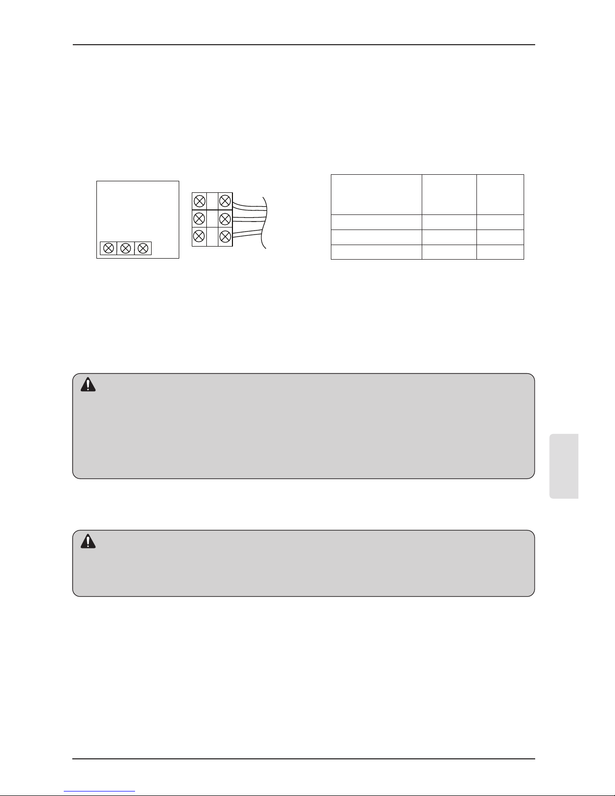
4. Please refer to the following directions when connecting the indoor unit and the
Thermostat together.
1) Please connect the cables as shown in the figure below when connecting the plug type cable from the
indoor unit’s C/BOX and the housing type of the extension cable.
2) When connecting Terminal Blocks of the indoor C/BOX and the Thermostat with the extension cable, refer
to the steps below.
① Remove the screw on the cable which is fastened to the Thermostat’s Terminal Block by loosening with a
screw driver.
② Remove the housing of the provided 32ft extension cable with a cutting nipper and peel it as shown in the
figure below. (when purchasing the extension cable at the site directly, please peel it as shown in the figure
below.)
Please check if the connectors are connected properly.
C/BOX Cable (Plug type)
Extension cable(housing type)
Indoor
Unit side
ڸ
ڹ
ں
※ڸ:AWG#24 / ڹ+ں : AWG#22
• Specification of Friedrich supplied extension cable : AWG#22, 3 core shielded.
• Apply enclosed noncombustible conduit(metal raceway) or use FT-6 rated cable or higher in case local
electric & building code that requires plenum(CMP) cable usage.
CAUTION
12V Red
Signal Yellow
GND Black
1.378 inch(35mm)
± 0.197 inch(5mm)
0.394 inch(10mm) ± 0.118 inch(3mm)
Owner’s & Installation Manual 7
ENGLISH
Installation instruction
③ Make sure each wire is securely fastened under each screw terminal and the wires are not in contact with
each other.
④ Please connect the Terminal blocks of indoor unit’s C/BOX and wired remote controller by referring to the
images and contents shown below.
Connect the yellow(signal) part of the Thermostat’s terminal block and the ‘YL’ part of the indoor unit’s
terminal block.
Connect the red(12 V) part of the Thermostat’s terminal block and the ‘RD’ part of the indoor unit’s terminal
block.
Connect the black(GND) part of the Thermostat’s terminal block and the ‘BK’ part of the indoor unit’s
terminal block.
❈ In case of loose screws or insufficient contact between the terminal and the wire, thermostat may not function
properly.
❈ When the power is off on the Thermostat, check the connection between the Thermostat and Terminal Block.
❈ Use an appropriate screwdriver for tightening the terminal screws. A screwdriver with a small head will strip
the screw head and make tightening difficult.
❈ Over-tightening terminal screw may cut wires or cause irreparable damage to thermostat.
5 Please use an extension cable if the distance between the Thermostat and the
indoor unit is longer than 32 ft (10 m).
• Installation work must be performed in accordance with the national wiring standards and local code by
authorized personnel only.
• Apply enclosed noncombustible conduit(metal raceway) or use cable above FT-6 in case of local electric &
building code that requires plenum(CMP)cable usage.
• AWG#22, 3 core shielded is recommended when using the large hole in the center of the backplate.
• AWG#24, 3 core shielded is recommended when using the side or top knock-out of the backplate.
CAUTION
When installing thermostat, installation should be flush to a flat wall surface, no installation below the typical
wall surface is allow. (Damage to temperature sensor will occur.)
Do not install the cable to be 164 ft (50 m) or longer. (Communication error can occur.)
CAUTION
YELLOW RED BLACK
Signal 12V GND
Thermostat PCB
Indoor unit
side
Thermostat PCB
Terminal
block Remark
Indoor
Terminal
block
Function
YELLOW YL Signal
RED RD 12V
BLACK BK GND
8 DWC1 Programmable Thermostat
Installation instruction
Installer setting mode is to set the detail function of the remote controller.
If the installer setting mode is not set correctly, it can cause problems to the product, user injury or
property damage. This must be set by an certificated installer, and any installation or change that is
carried out by a non-certificated person should be responsible for the results. In this case, free service
cannot be provided.
CAUTION
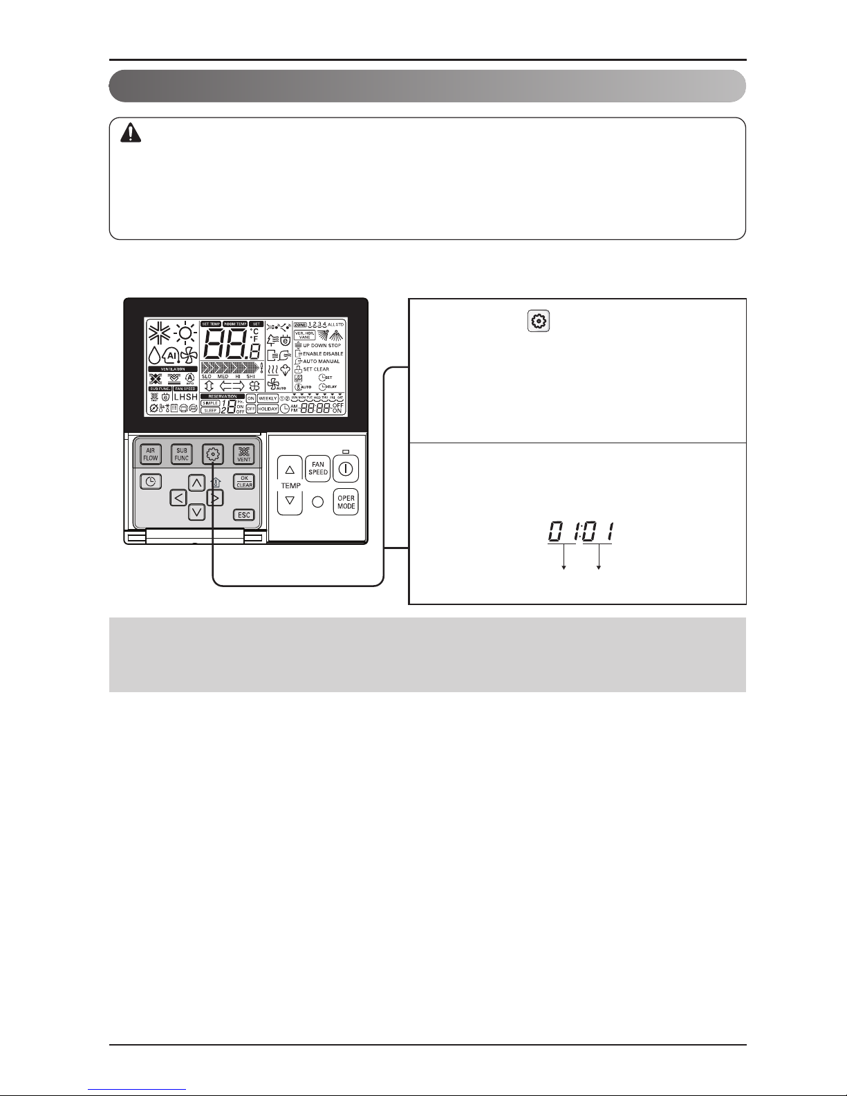
Installer Setting -How to enter installer setting mode
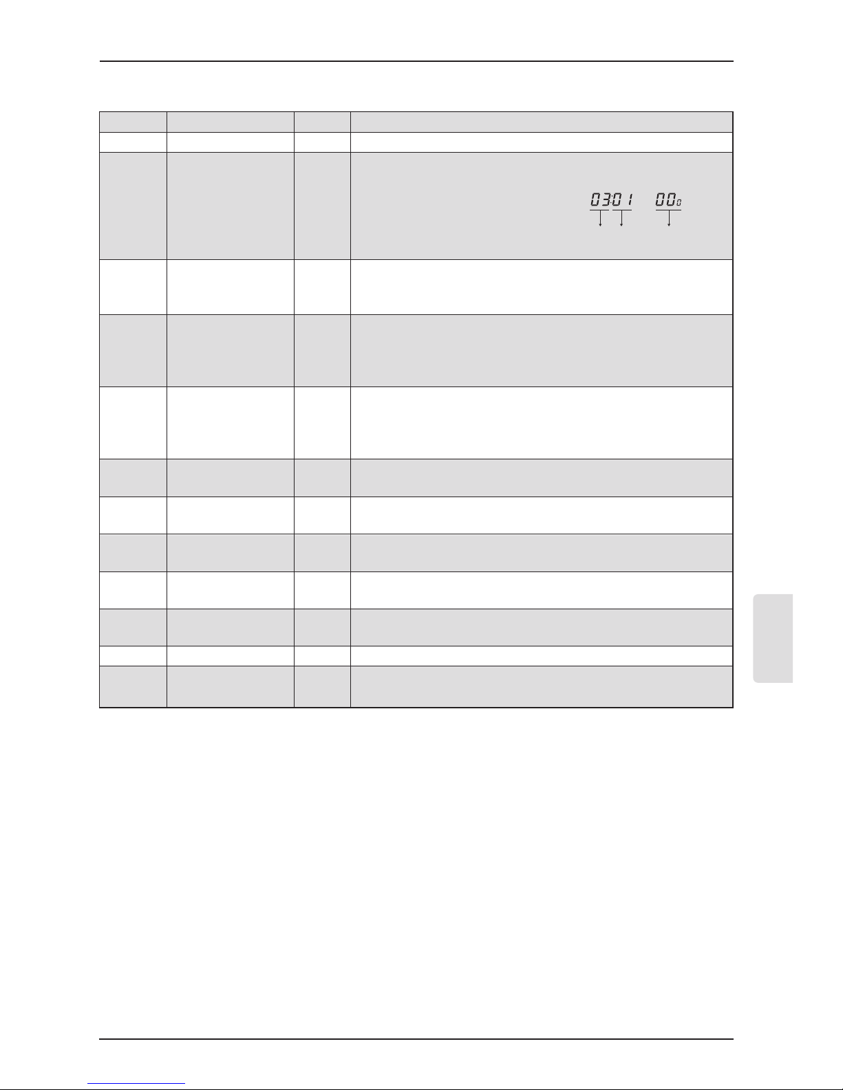
Function Code Value
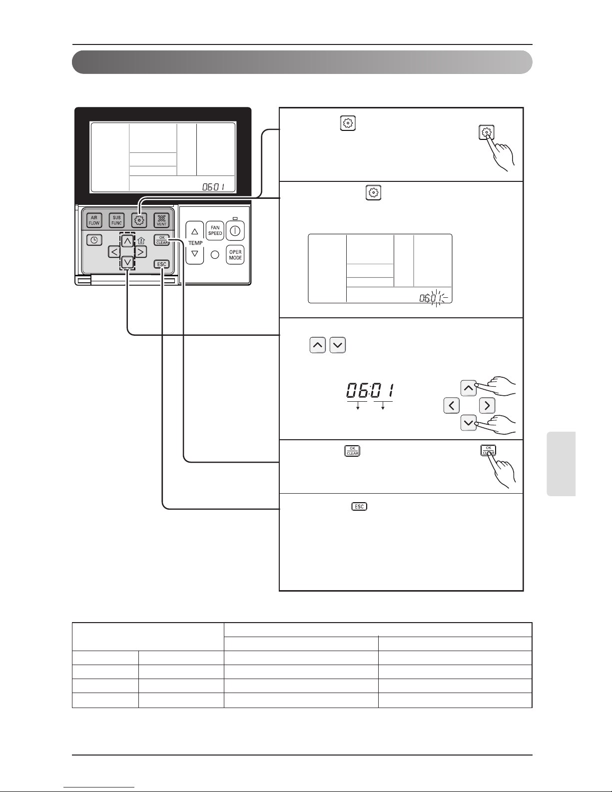
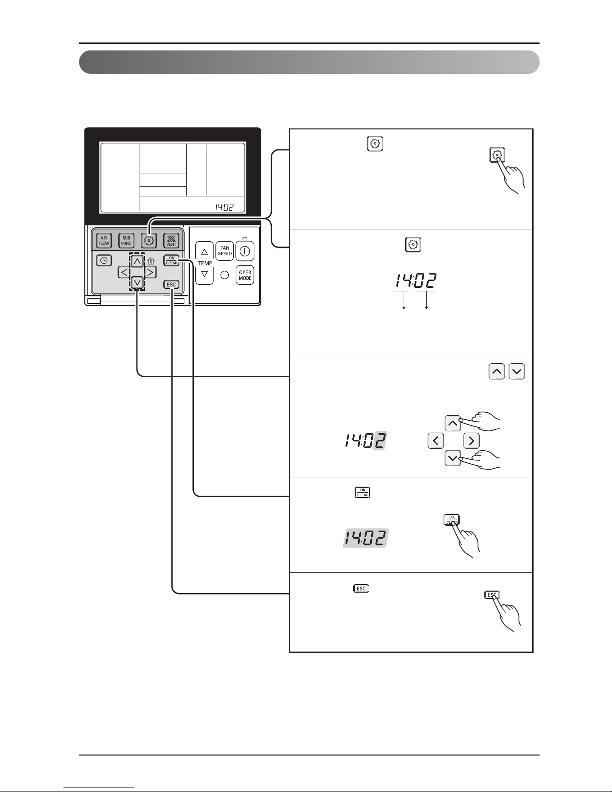
If pressing button long for 3 seconds,
it enters into remote controller setter
setup mode.
- If pressing once shortly, it enters into
user setup mode. Please press more
than 3 seconds for sure.
1
When you enter the setting mode
initially, Function code is displayed on
the bottom of the LCD screen.
2
•
Some categories of the menu may not be displayed according to the function of the
product, or the menu name may be different.
Owner’s & Installation Manual 9
ENGLISH
Installation instruction
<Installer Setting Code Table>
1) General air-conditioner product
❊ Some contents may not be displayed depending on the product function
No. Function Code Value
1 Test Run 01 01:Set
<ESP Step> <ESP Value> <Example>
01:VeryLow 0 ~ 255
02:Low
2 E.S.P. Value 03
03:Med
04:High
05:Very High
01:Remo
3 Thermistor 04 02:Indoor
03:2TH
01:Low
02:Med
4 Ceiling Height 05
03:High
04:Very High
01:V-H
02:F-H
5 Static Pressure 06
03:V-L
04:F-L
6 Dry Contact 09
00:Auto-Off
01:Auto-On
7
Release 3 Min.
10 01:Set
Delay
8 Zone State 11
01:Variable
02:Fixed
9
Celsius
12
00:Celsius
(Optimized only for U.S.A)
Fahrenheit Switching 01:Fahrenheit
10 Zone Type 13
00:Zone Controller
01:Damper Controller
11 Zone Number 14 02~04(Zone number)
12
Static Pressure
32
00: use static pressure (code 06) set value
Step 01~ 11: static pressure step (code 32) set value
Function Code ESP valueESP step

10 DWC1 Programmable Thermostat
Installation instruction
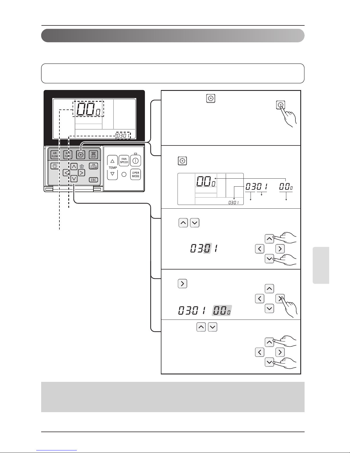
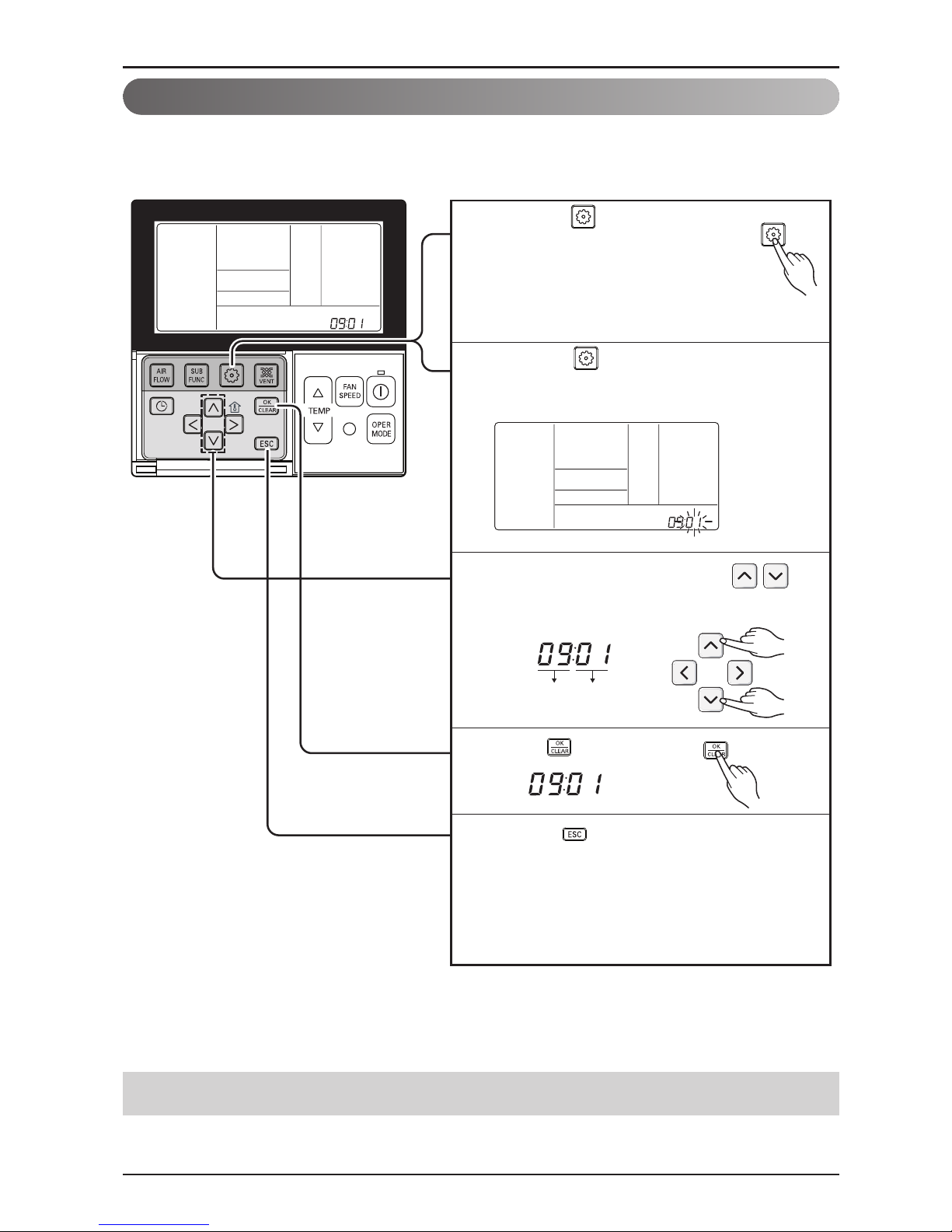
Function Code Set
Press button to start.
3
During the test run, pressing the below
button will exit the test run.
- Select operation, temperature
up/down, wind flow control, wind
direction, start/stop button.
4
Long press button for 3 seconds, it
enters into remote controller setting
mode.
- Press button with a short press,
controller enters user set up mode. To
ensure set up mode user may need to
press button for 3 seconds.
1
Setup figure '01' blinks at the lower part
of indication window.
2
Installer Setting - Test Run Mode
After installing the product, you must run a Test Run mode.
For details related to this operation, refer to the product manual.
Owner’s & Installation Manual 11
ENGLISH
Installation instruction
If entering into ESP setup mode by using
button, it indicates as the picture
below.
2
Select ESP fan step by pressing
button. (01: very low, 02: low,
03: medium, 04: high, 05: very high)
3
Move to ESP value setting by pressing
button.
(It is 000 when delivering
from the warehouse.)
4
Press button to setup ESP value.
(It is possible to setup ESP
value from 1 to 255, and 1 is
the smallest and 255 is the
biggest.)
5
Function code,
ESP code
ESP value
If pressing button long for 3
seconds, it enters into remote
controller setter setup mode.
- If pressing once shortly, it enters
into user setup mode. Please press
more than 3 seconds for sure.
1
Function Code ESP value
ESP step
Installer Setting - E.S.P.
• If you set ESP incorrectly, the air conditioner may malfunction.
• This setting must be carried out by a certificated-technician.
This is the function that decides the strength of the wind for each wind level and because this
function is to make the installation easier.
•
When setting ESP value on the product without very weak wind or power wind function, it
may not work.

12 DWC1 Programmable Thermostat
Installation instruction
Function code,
ESP code
ESP value
Press button to save.
7
Select ESP fan step again by using
button and setup ESP value, as No. 4
and 5, that corresponds each wind flow
6
Press button to exit.
❈ After setup, it automatically gets out of
setup mode if there is no button input
for 25 seconds.
❈ When exiting without pressing set
button, the manipulated value is not
reflected.
8
• Please be careful not to change the ESP value for each fan step.
• It does not work to setup ESP value for very low/power step for some products.
• ESP value is available for specific range belongs to the product.
Owner’s & Installation Manual 13
ENGLISH
Installation instruction
Function Code Thermistor setting
Set Thermistor value by pressing
button. (01: Remote Controller,
02: Indoor, 03: 2TH)
3
Press button to save.
4
5
If moving to room temperature perception
sensor selection menu by pressing
button, it indicates as picture below.
2
If pressing button long for 3
seconds, it enters into remote
controller setter setup mode.
- If pressing once shortly, it enters
into user setup mode. Please press
more than 3 seconds for sure.
1
Pressing button will exit settings mode.
❈ After setup, it automatically gets out of
setup mode if there is no button input for
25 seconds.
❈ When exiting without pressing set button,
the manipulated value is not reflected.
Installer Setting - Thermistor
❊ The function of 2TH has different operation characteristics according to the product.
Temperature sensor selection Function
01 Remote controller Operation in remote controller temperature sensor
02 Indoor unit Operation in indoor unit temperature sensor
03 2TH
Cooling
Operation of higher temperature by comparing indoor unit's and wired
remote controller’s temperature.
(There are products that operate at a lower temperature.)
Heating
Operation of lower temperature by comparing indoor unit's and wired remote
controller's temperature.
<Thermistor Table>
This is the function to select the temperature sensor to judge the room temperature.
14 DWC1 Programmable Thermostat
Function Code Thermistor setting
Select ceiling height value by pressing
button. (01:Low, 02:Medium,
03:High, 04:Very high)
3
Press button to save.
4
5
If moving to ceiling height selection menu by
pressing button, it indicates as picture
below.
2
If pressing button long for 3
seconds, it enters into remote
controller setter setup mode.
- If pressing once shortly, it enters
into user setup mode. Please press
more than 3 seconds for sure.
1
Pressing button will exit settings mode.
❈ After setup, it automatically gets out of
setup mode if there is no button input for
25 seconds.
❈ When exiting without pressing set button,
the manipulated value is not reflected.
Installation instruction
Installer Setting - Ceiling Height Selection
This function is to adjust FAN Airflow rate according to ceiling height (For ceiling type product)
• Ceiling height setting is available only for some products.
• Ceiling height of ‘Very high’ function may not exist depending on the indoor unit.
• Refer to the product manual for more details.
Ceiling Height Level Description
01 Low Decrease the indoor airflow rate 1 step from standard level
02 Medium Set the indoor airflow rate as standard level
03 High Increase indoor airflow rate 1 step from standard level
04 Very high Increase indoor airflow rate 2 steps from standard level
<Ceiling Height Selection Table>
Owner’s & Installation Manual 15
ENGLISH
Installation instruction
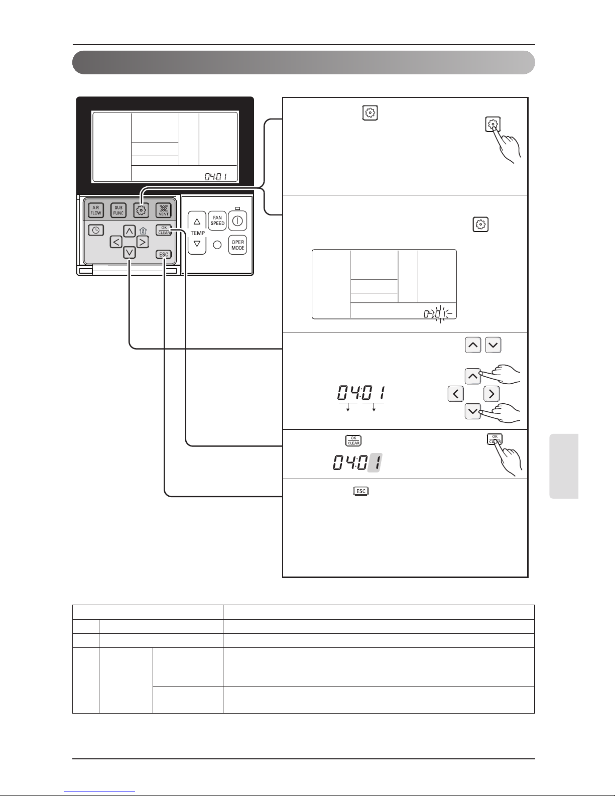
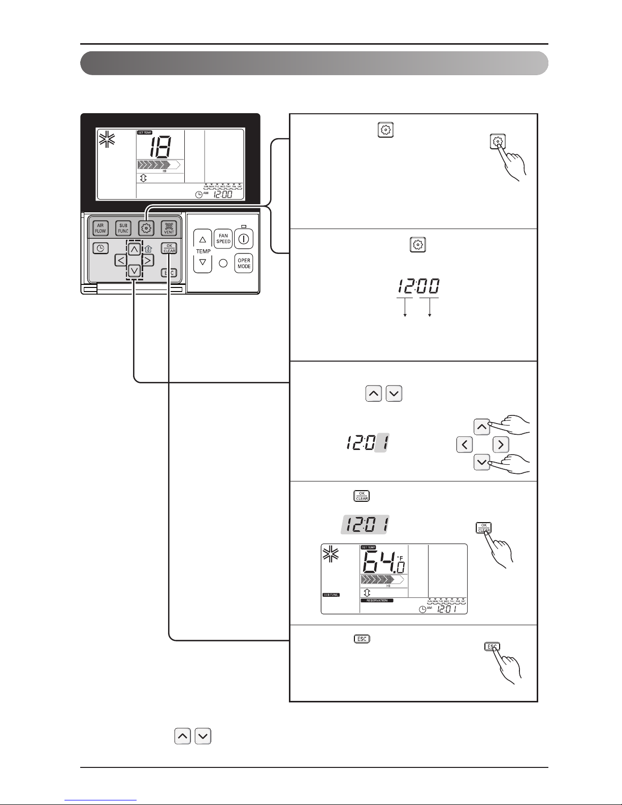
Function Code Pressure
Press button for 4 seconds
to enter the installer setting
mode until timer segment
displays “01:01”.
1
Select static pressure by pressing
button.
(01:V-H, 02:F-H, 03:V-L, 04:F-L)
3
Press button to save.
4
5
Pressing button will exit settings mode.
❈ After setup, it automatically gets out of
setup mode if there is no button input for
25 seconds.
❈ When exiting without pressing set button,
the manipulated value is not reflected.
If pressing button repeatedly, it
moves to static pressure selection menu
as picture below.
2
Installer Setting - Static Pressure Setting
This function is applied to only duct type. Setting this in other cases will cause malfunction.
Pressure selection
Function
Zone state ESP standard value
01 V-H Variable High
02 F-H Fixed High
03 V-L Variable Low
04 F-L Fixed Low
<Static Pressure Setting Table>
16 DWC1 Programmable Thermostat
Installation instruction
Installer Setting - Dry Contact Mode Setting
Function Code Dry Contact
setting value
Select Dry contact setting by
pressing button.
(00 : Manual, 01 : Automatic)
3
Press button to save.
4
If pressing button long for 3
seconds, it enters into remote
controller setter setup mode.
- If pressing once shortly, it enters
into user setup mode. Please press
more than 3 seconds for sure.
1
If pressing button repeatedly, it moves to
remote controller dry contact mode setup
menu as picture below.
2
Pressing button will exit settings mode.
❈ After setup, it automatically gets out of
setup mode if there is no button input for
25 seconds.
❈ When exiting without pressing set button,
the manipulated value is not reflected.
5
Dry contact function is the function that is possible to use only when dry contact equipment is
separately purchased/setup.
• Please refer to dry contact manual for more details.
▶
What is Dry Contact?
Like hotel card key and it is the signal of the point of contact when using air-conditioner by
interlocking.

Owner’s & Installation Manual 17
ENGLISH
Function Code Zone State
fixing mode
Select Zone State rate fixing mode by
pressing button.
(01: Variable, 02: Fixed)
3
Press button to save.
4
If pressing button long for 3
seconds, it enters into remote
controller setter setup mode.
- If pressing once shortly, it enters
into user setup mode. Please press
more than 3 seconds for sure.
1
If moving to ceiling height selection menu by
pressing button, it indicates as picture
below.
2
Pressing button will exit settings mode.
❈ After setup, it automatically gets out of
setup mode if there is no button input for
25 seconds.
❈ When exiting without pressing set button,
the manipulated value is not reflected.
5
Installation instruction
Installer Setting - Zone State
It is the function to setup indoor unit's wind flow to variable or fixed.
- Variable : Comp ON, setup airflow. Comp OFF, weak wind
- Fixed : Comp ON, setup airflow. Comp OFF, setup airflow
18 DWC1 Programmable Thermostat
Installation instruction
Installer Setting - Celsius / Fahrenheit Switching
Function Code conversion mode value
If pressing button long for 3
seconds, it enters into remote
controller setter setup mode.
- If pressing once shortly, it
enters into user setup mode.
Please press more than 3 seconds for
sure.
1
Press button to exit or
system will automatically exit
after 25 seconds without any
input.
5
Repeat pressing button to select
Function code 12.
Ex) Fahrengeit Setting
2
Select Temperature unit mode by
pressing button.
(00: Celsius, 01: Fahrenheit)
3
Press button to save or release.
4
This function is used for switching the display between Celsius and Fahrenheit.
(Optimized only for U.S.A)
❈ Whenever press button in Fahrenheit mode, the temperature will increase/drop 2
degrees.
Owner’s & Installation Manual 19
ENGLISH
Installation instruction
If pressing button long for 3
seconds, it enters into remote
controller setter setup mode.
- If pressing once shortly, it
enters into user setup mode.
Please press more than 3 seconds for
sure.
1
Function Code Zone type value
Press button to exit or
system will automatically exit
after 25 seconds without any
input.
5
Repeat pressing button to select
Function code 13.
Ex) Setting the Zone Type as "New"
2
Select Zone Type by pressing
button
(00:Old, 01:New)
3
Press button to save or release.
4
Installer Setting - Zone Type Setting
This function is only available on some products.
It is possible to setup zone new type or old one of the product which is available to install the damper
controller.
If you set zone number incorrectly, the product may malfunction especially in zone control.
This function must carried out by a certificated-technician.
CAUTION
20 DWC1 Programmable Thermostat
Installation instruction
If pressing button long for 3
seconds, it enters into remote
controller setter setup mode.
- If pressing once shortly, it enters
into user setup mode. Please press
more than 3 seconds for sure.
1
Function Code Zone Number installed
Press button to exit or
system will automatically exit
after 25 seconds without any
input.
5
Repeat pressing button to select
Function code 14.
Ex) Setting the Zone Number for "2"
2
Select Zone Number by pressing
button
(02~04 : number of zone installed)
3
Press button to save or release.
4
Installer Setting - Zone Number Setting
This function is only available on some products.
Zone Number is to set the number of installed zones. It's possible to control only in zone new type

Owner’s & Installation Manual 21
ENGLISH
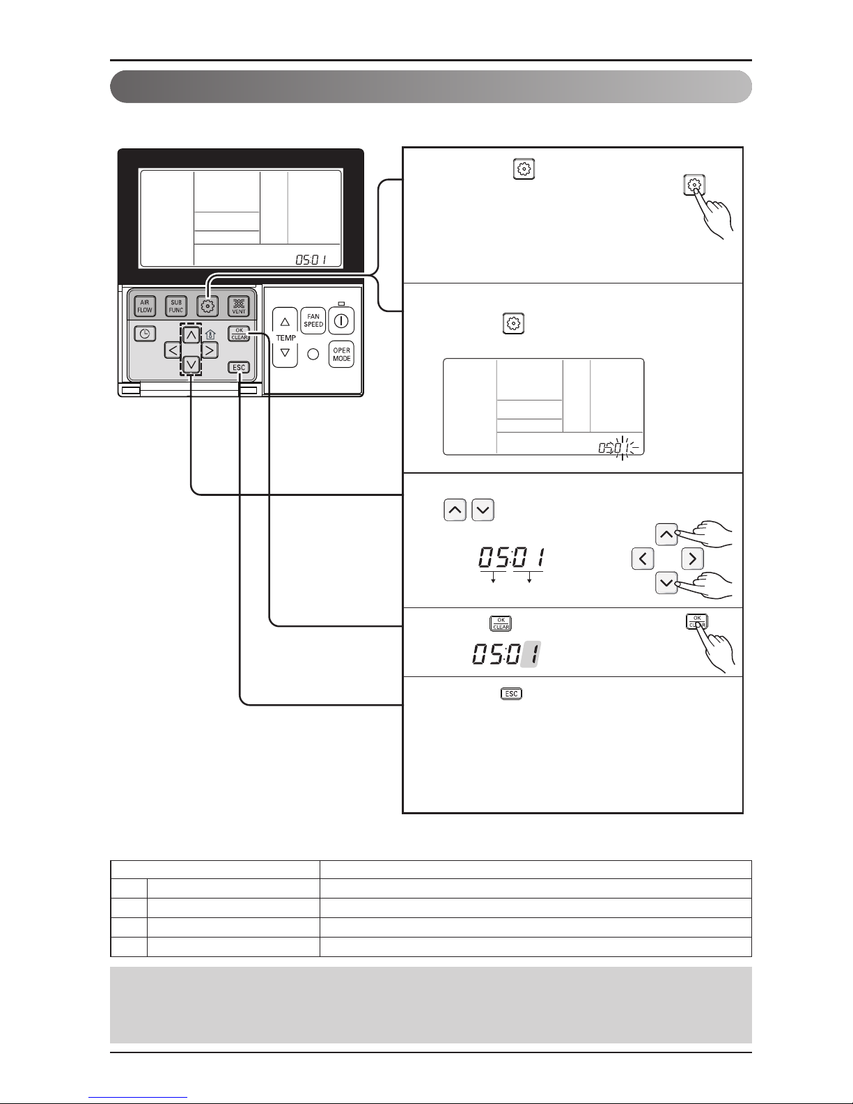
Installation instruction
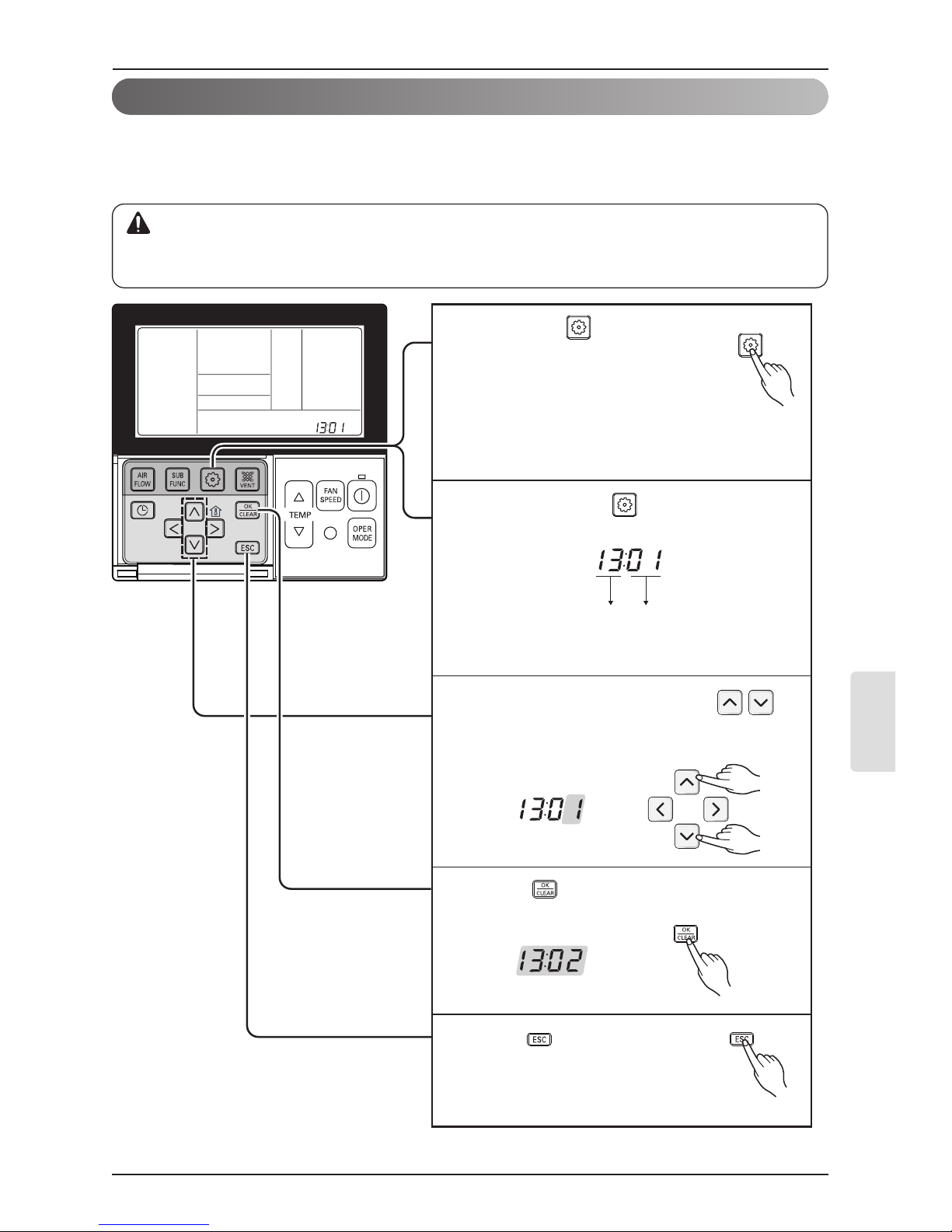
Press button for 4 seconds to
enter the installer setting mode until
timer segment displays “01:01”.
1
Pressing button will exit settings mode.
❈ After setup, it automatically gets out of
setup mode if there is no button input for
25 seconds.
❈ When exiting without pressing set button,
the manipulated value is not reflected.
5
If pressing button repeatedly, it
moves to static pressure selection menu
as picture below.
2
Select static pressure by pressing
button.
00: use static pressure (code 06) set value
01~ 11: static pressure step (code 32) set value
3
Press button to save.
4
Function Code pressure
Installer Setting - Static Pressure Step Setting
This function is applied to only duct type. Setting this in other cases will cause malfunction.
This function is only available on some models.
This is the function that static pressure of the product is divided in 11 steps for setting.
• Static Pressure (Code 06) setting will not be used if Static Pressure Step (Code 32)
setting is being used.
• For the static pressure value for each step, refer to the indoor unit in the product
manual.
22 DWC1 Programmable Thermostat
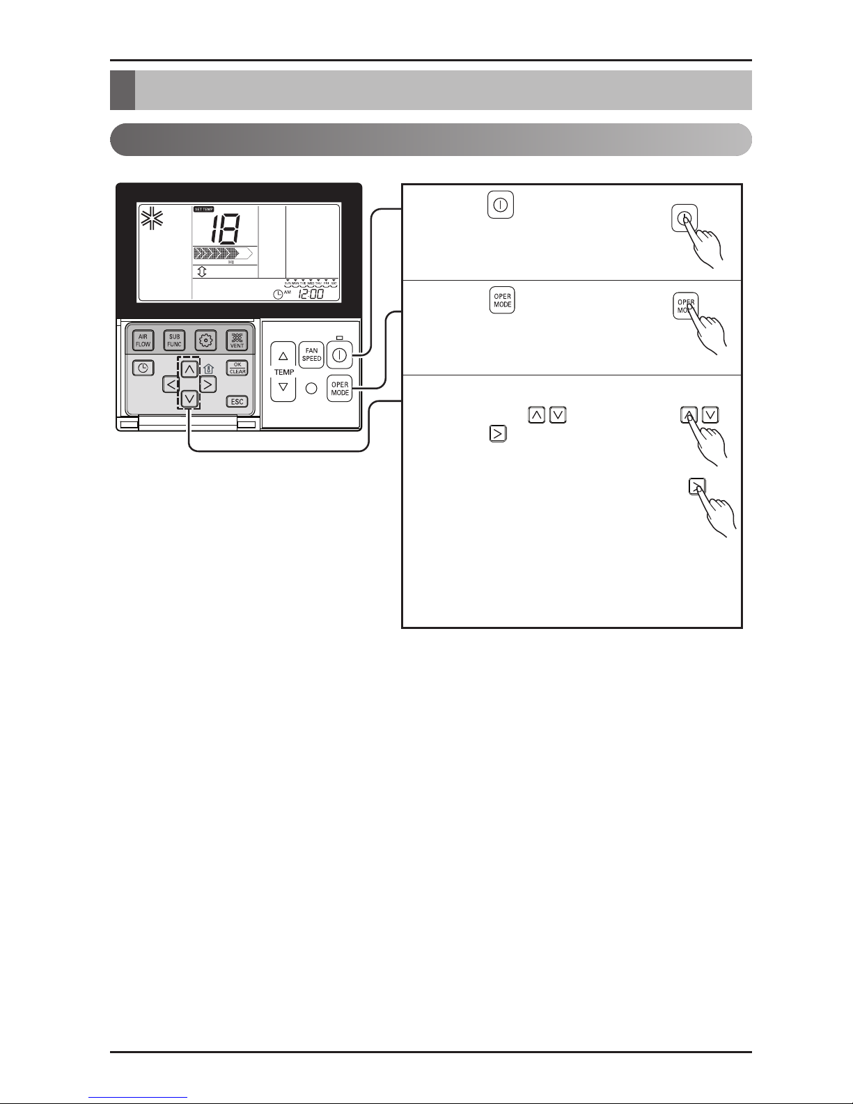
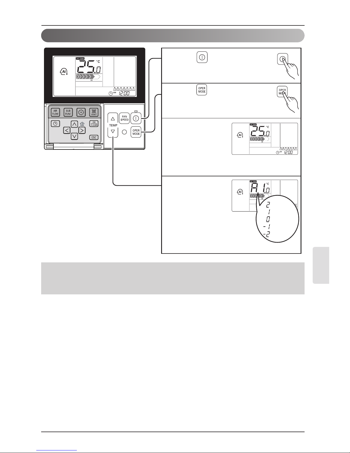
Standard Operation - Standard Cooling
Press button to turn on the
indoor.
1
Press button to select
Cooling operation mode.
2
Adjust the desired temperature
by pressing buttons.
Press button to check the
Room temperature.
When setting the desired
temperature higher than room
temperature, only ventilation
wind is blow out instead of
cooling wind.
3
❈ Setting Temp Range : 64 °F~86 °F(18 °C~30 °C)
It cools the room by comfortable and clean wind.
Owner's instruction
Owner's instruction
Owner’s & Installation Manual 23
ENGLISH
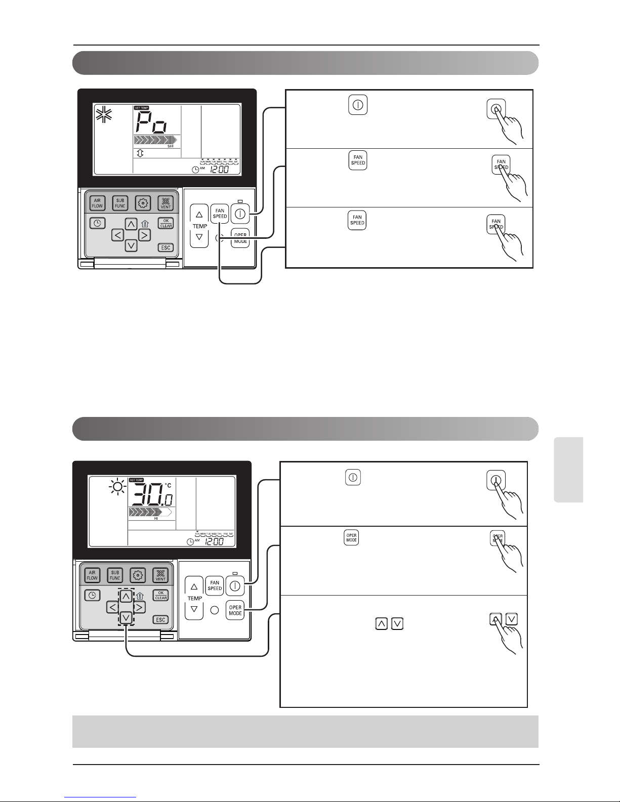
Owner's instruction
Press button to turn on the
indoor.
1
Press button to select
cooling operation mode.
2
Press button continuously
until 'Po' displayed.
3
It supplies warm wind to the indoor
Standard Operation - Heating Mode
Press button to turn on the
indoor.
1
Press button to select
Heating mode.
(To check the indoor temperature,
press the room temperature button.)
2
Adjust the desired temperature
by pressing buttons.
When setting the desired
temperature lower than room
temperature, there is only
ventilation wind.
3
What is Surge Cooling?
• Desired temperature: Po (actually 64 °F)
• Wind flow: power wind
• Wind direction: fix to air-cooling position
❈
Partial product has no power air-cooling function.
• Heating drive only operates at the cooling and heating model.
• Heating doesn't operate at cooling exclusive model.
It make room temperature
drop fast by running
}
Standard Operation - Surge Cooling
24 DWC1 Programmable Thermostat
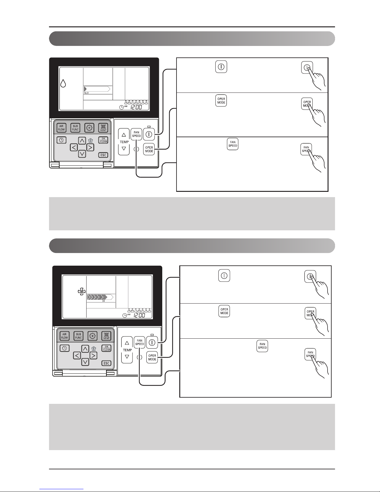
Owner's instruction
Press button to turn on the
indoor.
1
Press button to select
Dehumidification mode.
The temperature setting can not be
adjusted during operation this mode.
2
Press the button to select
airflow rate feeble → weak →
medium → strong → automatic.
(The initial wind powerfulness of
humidity removal drive is 'weak'.)
3
Press button to turn on the
indoor.
1
Press button to select Fan
Mode.
2
Every time pressing button, you
can select wind flow in order of Very
Low → Low → Medium → High →
Very High.
When running ventilation,
compressor of AHU doesn't work.
3
Standard Operation - Fan Mode
It removes humidity while air-cooling weakly.
It blows the air as it is in the indoor, not the cold wind.
• In rainy season or high humidity climate, it is possible to operate simultaneously dehumidifier and
cooling mode to remove humidity effectively.
• The menu item of wind powerfulness might not be partially selected according to the product.
• Ventilation drive does not release cool wind but general fan
• Because it releases the wind that has no temperature difference from the room, it functions to
circulate the inside air.
• The menu item of wind powerfulness might not be partially selected according to the product.
Standard Operation - Dehumidification Mode
Owner’s & Installation Manual 25
ENGLISH
Owner's instruction
Press button to turn on the
indoor.
1
Press button to select
Artificial intelligence Mode.
2
You can adjust
the temperature
as the picture on
the right for
cooling and
heating model.
3
For the case of
cooling exclusive,
as the picture on
the right, you can
adjust the
temperature from
hot to cold, from
"-2" to "2" based
on "00".
4
When cold
When cool
When appropriate
When warm
When hot
Standard Operation - Auto Operation Mode
During operating Auto Operation mode:
• We can use the FAN SPEED button
• We can change manually to other operation mode.

26 DWC1 Programmable Thermostat
Owner's instruction
Standard Operation - Temperature Setting/Room Temperature Check
We can simply adjust the desired
temperature.
• Press the buttons to adjust the
desired temperature.
: Increase Temp. per one time
pressing
: Decrease Temp. per one time
pressing
Cooling operation:
- The cooling mode doesn't work if
desired temperature is higher than room
temperature Please lower the desired
temperature.
Heating operation:
- The heating mode doesn't work if desired
temperature is lower than room
temperature Please increase the desired
temperature.
1
Whenever press button, the room
temperature will be displayed within 5
seconds.
After 5 seconds, it turns to display the
desired temperature.
Because of location of remote controller,
the real room temperature and the this
displayed value can be different
1
Temperature Setting
Room Temperature Check
• For air-cooling drive, from 64 °F ~ 86 °F, and for heating drive, from 60 °F ~ 86 °F, you can select
desired temperature.
• 10 °F is proper for the difference between room and outside temperature.
• Room temp: Indicate the current room
temperature.
• Set temp: Indicate the temperature that user
want to set.
Owner’s & Installation Manual 27
ENGLISH
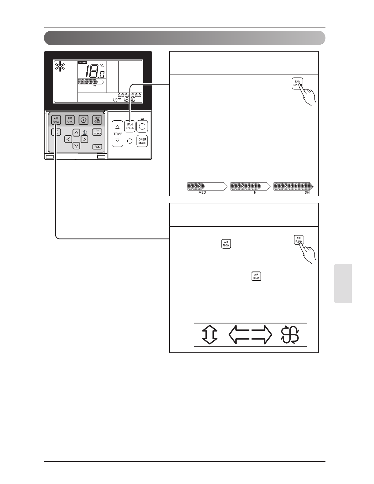
Standard Operation - Airflow Setting
Please setup desired wind
powerfulness by wind powerfulness
button.
• Every time you press wind
powerfulness, you can select the wind flow in
order of ‘feeble → weak → weak medium →
medium → medium strong → strong → power
→ automatic’.
• The menu item might not be partially
selected according to product function.
• Please refer to product manual for product’s
detailed function.
1
Please set desired wind direction
by pressing button.
You can select wind direction of
(comfortable wind → Up/Down and
Right/Left → Right/Left →
Up/Down) by pressing button.
Partial item of wind directions might not be
selected according to product function.
Please refer to product manual for product’s
detailed function.
1
Wind powerfulness : You can simply adjust
desired wind powerfulness.
Wind direction : You can simply adjust desired
wind direction.
Owner's instruction

28 DWC1 Programmable Thermostat
Owner's instruction
Optimal energy savings by adjusting set point to room temp.
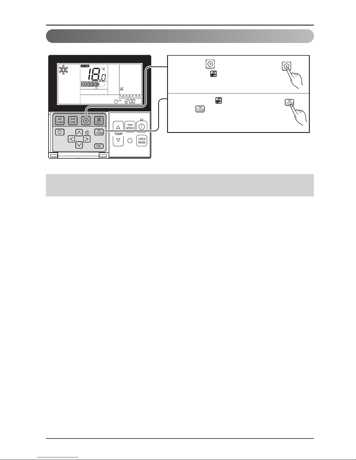
Sub function - Energy-Saving Cooling Operation
Repeatedly pressing button
until icon flash.
1
Operate or cancel Energy-Saving
function by pressing
button.
(To cancel power saving function,
you move to power saving menu by
pressing button, and then if pressing
button, power saving icon
disappears and the function is cancelled.
)
2
Press button to exit.
❈ After setup, it automatically
gets out of setup mode if there
is no button input for 25
seconds.
❈ When exiting without pressing set
button, the manipulated value is not
reflected.
3
• Power saving function is possible to setup only when running air-cooling.
• Power saving function might not be operated at the partial product.

Owner’s & Installation Manual 29
ENGLISH
Owner's instruction
It is the function to use preventing children or others from careless using.
Function setting - Child Lock
Press button repeatedly until
the is flashing.
1
If moving to 'setup' icon area by
using button, 'setup' icon
blinks, and child lock function is
setup if pressing button at
that time.
2
When cancelling lock function, if moving
to 'cancel' icon by pressing button
and then, pressing button, child lock
function is cancelled.
3
Press button to exit.
❈ After setup, it automatically gets out of
setup mode if there is no button input
for 25 seconds.
❈ When exiting without pressing set
button, the manipulated value is not
reflected.
4
30 DWC1 Programmable Thermostat
This function is to clear the indicator of indoor filter cleaning.
Function setting - Filter Sign Clear
Press button repeatedly
until the is flashing.
1
When the is flashing, press
the to clear this display
2
Owner's instruction
• When filter is covered by dust, it will reduce cooling/heating efficiency and accumulate more
electric power. Therefore. do clean the filter whenever cleaning time is expired.
❈ Filter cleaning indication is automatically cancelled without the separate cancellation after certain
period of time.
 Loading...