

Friedrich DH30, DH40, DH50 Service Manual

MODELS:
DH30
DH40
DH50
DeHumSrv (03/02)
CONTENTS
INTRODUCTION
PREFACE
SAFETY PRECAUTIONS ........................................................................................................... 4
FEATURES ................................................................................................................................. 4
DIMENSIONS ............................................................................................................................. 4
SPECIFICATIONS ...................................................................................................................... 5
CONTROL .................................................................................................................................. 6
HOW TO OPERATE DEHUMIDIFIER ........................................................................................ 6
HOW DOES THE DEHUMIDIFIER WORK? ............................................................................... 6
LOCATION FOR THE DEHUMIDIFIER ...................................................................................... 6
MICROSWITCH .......................................................................................................................... 7
AUTO DEFROST ........................................................................................................................ 7
HUMIDITY CONTROLLER ......................................................................................................... 7
DRIER ........................................................................................................................................ 7
CIRCUIT DIAGRAM .............................................................................. 8
DISASSEMBLY INSTRUCTIONS
MECHANICAL PARTS ............................................................................................................... 10
BUCKET AND AIR FILTER ......................................................................................................... 10
FRONT GRILLE .......................................................................................................................... 10
CABINET AND CONTROL BOX ................................................................................................. 10
CONTROL PARTS ..................................................................................................................... 11
ROTARY, SWITCH / SWITCH ASSEMBLY, ROTARY / PWB (PCB) ASSEMBLY,
DISPLAY / PWB (PCB) ASSEMBLY, MAIN ................................................................................ 11
CAPACITOR ............................................................................................................................... 11
SENSOR ASSEMBLY ................................................................................................................ 11
MICRO SWITCH ASSEMBLY ..................................................................................................... 11
POWER CORD ASSEMBLY ....................................................................................................... 11
FAN AND MOTOR ...................................................................................................................... 12
SHROUD AND BARRIER ........................................................................................................... 12
REFRIGERATING CYCLE ......................................................................................................... 13
CONDENSER, EVAPORATOR AND CAPILLARY TUBE (HEAT EXCHANGE ASSEMBLY) ..... 13
P.T.C. OR OVERLOAD PROTECTOR (O.L.P.) FOR RECIPROCATING COMPRESSOR ........ 13
ROTARY COMPRESSOR .......................................................................................................... 13
HOW TO REPLACE REFRIGERATION SYSTEM ...................................................................... 14
TROUBLESHOOTING GUIDE ............................................................. 16
EXPLODED VIEW - INTRODUCTION .................................................. 19
REPLACEMENT PARTS LIST ............................................................. 21
INTRODUCTION
This service manual was written to assist the professional service technician to quickly and accurately
diagnose and repair any malfunctions of this product. This manual, therefore, will deal with all sub-
jects in a general nature. (i.e. All text will pertain to all models).
IMPORTANT:
It will be necessary for you to accurately identify the Model you are servicing, so you can be
certain of a proper diagnosis and repair. (See Unit Identification.)
The information contained in this manual is intended for use by a qualified service technician
who is familiar with the safety procedures required to repair, and who is equipped with the proper
tools and test instruments.
Repairs made by unqualified persons can result in hazards subjecting them to the risk of injury or
electrical shock which can be serious or even fatal not only to them, but also to anyone being
served by the equipment.
If you perform service on equipment, you must assume responsibility for any bodily injury or
property damage which may result to you or others. Friedrich Air Conditioning Company will not
be responsible for any injury or property damage arising from improper service, and/or service
procedures.

PREFACE
This Service Manual provides various service information, containing the mechanical and electrical parts etc. This dehu-
midifier was manufactured and assembled under the strict quality control system. The refrigerant is charged at the factory.
Be sure to read the safety precaution prior to servicing the unit.
SAFETY PRECAUTIONS
• Disconnect the power supply before servicing or replacing any component.
• Do not cut off the grounding prong or alter the plug in any manner under any circumstances.
FEATURES
Quiet
High efficiency
Adjustable humidistat
Automatic defrost
Automatic shut-off
Bucket-full indicator light
Easy roll casters
Large capacity, removable bucket.
Washable air filter
2 fan speeds
Drain hose connection.
DIMENSIONS (in/mm)
12 5/8"(320)
17 1/2" (445)
13 3/8" (340)
S
cO
r---t__.
0
ol
k,J _

SPECIFICATIONS
-__-_ MODELS
ITEMS ___
CAPACITY (Pint/Day)
POWER SUPPLY (Phase, V, Hz)
REFRIGERANT
REFRIGERANT CHARGE, oz(g)
THERMISTOR
HUMIDITY SENSOR
P.T.C.
ASSEMBLY
PROTECTOR
CAPACITOR
MAXIMUM
AMPERE
VOLTAGE
DH3011B
30
R134a R22
4.76(135) 5.11 (145) 7.05(200)
OPEN : 28.4°F(-2°C +_0.5)
CLOSE : 53.6°F(12°C_+0.5)
CONTROL RANGE : 20% - 80% RH
NORMAL SETTING : 40% RH
7A
300V
• OVERLOAD PROTECTOR FOR COMPRESSOR
• INTERNAL PROTECTOR(FUSE) FOR MOTOR
DH4010E
4O
1{], 115V, 60Hz
251JF,270VAC
DH5010E
50
SWITCH, ROTARY
MOTOR ASSEMBLY, SINGLE
SWITCH ASSEMBLY, MICRO
OUTSIDE
DIMENSIONS
W x H x D, n. (mm) WITH BUCKET
NET WEIGHT, Lbs (Kg)
-_ NOTE : Specifications are subject to minor change without notice for further improvement.
IWITHOUT BUCKET
Shaded polo motor, 65W/1A j., Thermal cutoff : 266°F/130°C
12 5/8 x 20 7/8 x 13 3/8 (320 x 530 x 340)
12 5/8 x 20 7/8 x 17 1/2 (320 x 530 x 445)
<215) k 38(17.2) ! 39(17.7147
6A/125VAC, 12A/250VAC
16A/125VAC, 8A/250VAC
L l
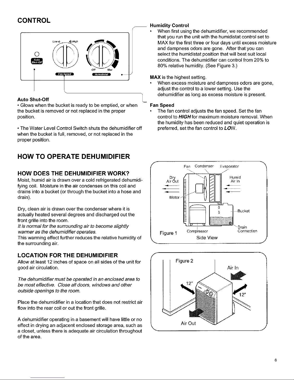
CONTROL
O
Off Max
Auto Shut-Off
• Glows when the bucket is ready to be emptied, or when
the bucket is removed or not replaced in the proper
position.
• The Water Level Control Switch shuts the dehumidifier off
when the bucket is full, removed, or not replaced in the
proper position.
HOW TO OPERATE DEHUMIDIFIER
Humidity Control
When first using the dehumidifier, we recommended
that you run the unit with the humidistat control set to
MAX for the first three or four days until excess moisture
and dampness odors are gone. After that you can
select the humidistat position that will best suit local
conditions. The dehumidifier can control from 20% to
80% relative humidity. (See Figure 3.)
MAX isthe highest setting.
When excess moisture and dampness odors are gone,
adjust the control to a lower setting. Use the
dehumidifier as long as excess moisture is present.
Fan Speed
The fan control adjusts the fan speed. Set the fan
control to HIGHfor maximum moisture removal. When
the humidity has been reduced and quiet operation is
preferred, set the fan control to LOW.
HOW DOES THE DEHUMIDIFIER WORK?
Moist, humid air is drawn over a cold refrigerated dehumidi-
fying coil. Moisture in the air condenses on this coiland
drains into a bucket (or through the bucket into a hose and
drain).
Dry, clean air is drawn over the condenser where it is
actually heated several degrees and discharged out the
front grille into the room.
It is normal for the surrounding air to become slightly
warmer as the dehumidifier operates.
This warming effect further reduces the relative humidity of
the surrounding air.
LOCATION FOR THE DEHUMIDIFIER
Allow at least 12 inches of space on all sides of the unitfor
good air circulation.
The dehumidifier must be operated in an enclosed area to
be most effective. Close all doors, windows and other
outside openings to the room.
Place the dehumidifier in a location that does not restrict air
flow into the rear coil or out the front grille.
Ai? ut
Motor
Figure 1
Fan Condenser Evaporator
_ jJ
Air In
I "Drain
Compressor Connection
Side View
J
Figure 2
Air In
A dehumidifier operating in a basement will have little or no
effect in drying an adjacent enclosed storage area, such as
a closet, unless there is adequate air circulation throughout
of the area.
Air Out
J

MICROSWlTCH
The microswitch assembly, which is located on the barrier inside the unit, automatically turns the dehumidifier off when the
bucket is full. (NOTE: the Auto Shut-Off light will illuminate to indicate the bucket should be emptied). When the bucket is
reinstalled, the unit will resume dehumidification.
AUTO DEFROST
When frost builds up on the cooling coils, the compressor wilt cycle off until the frost melts. The fan will continues to run.
NOTE: This unit is designed to be operated at temperatures above 65°F (18°C). If the dehumidifier is operated in
low temperature conditions where the temperature and humidity of the room are low, frost can form on the evapo-
rator coil and cause the unit to short cycle.
HUMIDITY CONTROL
The humidistat automatically maintains the relative humidity
in the room.
For MORE humidification, turn the dial towards MAX.
For LESS dehumidification, turn the dial towards OFF.
When the relative humidity in the room INCREASES to the
selected level, the dehumidifier STARTS automatically.
When the relative humidity DECREASES to the selected
level, the dehumidifier wilt stop automatically.
NOTE: The relative humidity levels shown in Figure 3 are
approximate values.
DRIER
A dryer is usedto trap noncendensables in the sealed
system.
42%
421/_R,H_ 40"/o
50 Yo / J 35%
,0%
70%°/'--;/ I I _,' /I 2o5°/o
OffS DEA1 DIAL _'Ma/v _ x.
Figure 3
NOTE: The drier must be replaced any time a sealed
system repair is performed. The drier must be installed
at the inlet of the capillary tubes.
_ Drier
Figure 4
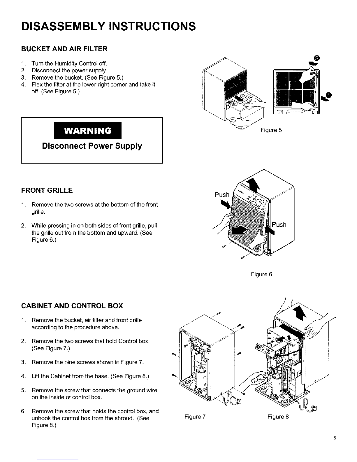
DISASSEMBLY INSTRUCTIONS
BUCKET AND AIR FILTER
1. Turn the Humidity Control off.
2. Disconnect the power supply.
3. Remove the bucket. (See Figure 5.)
4. Flex the filter at the lower right corner and take it
off. (See Figure 5.)
Disconnect Power Supply
Figure 5
FRONT GRILLE
1. Remove the two screws at the bottom of the front
grille.
2. While pressing in on both sides of front grille, pull
the grille out from the bottom and upward. (See
Figure 6.)
CABINET AND CONTROL BOX
1. Remove the bucket, air filter and front grille
according to the procedure above.
2. Remove the two screws that hold Control box.
(See Figure 7.)
3. Remove the nine screws shown in Figure 7.
Push
Figure 6
%
4. Liftthe Cabinet from the base. (See Figure 8.)
5. Remove the screw that connects the ground wire
on the inside ofcontrol box.
6 Remove the screw that holdsthe control box, and
unhook the controlbox from the shroud. (See
Figure 8.)
Figure 7 Figure 8
 Loading...