


FRIEDLAND Wirefree AlarmInterface Module Installation And Operating Instructions Manual
Wirefree Alarm
Interface Module
Installation and Operating Instructions

These instructions should be read in conjunction with your Alarm System
Installation and Operating Manual and the Smoke Alarm instructions, the
y
should be retained for future reference.
DECLARATION
Friedland hereby declares that this
wirefree Alarm Interface Module is
in compliance with the essential
requirements and other relevant
provisions of the R&TTE directive,
1999/5/EC.
INTRODUCTION
This Interface Module is designe d for
use with Friedland Wirefree Intruder
Alarm systems incorporating a
suitable Control Panel and operating
at 433MHz only .
When the connected Smoke Alarm
activates, the Interface Module
provides a link to the alarm system
that will generate an alarm on your
security system.
POSITIONING THE
INTERFACE MODULE AND
SMOKE ALARM
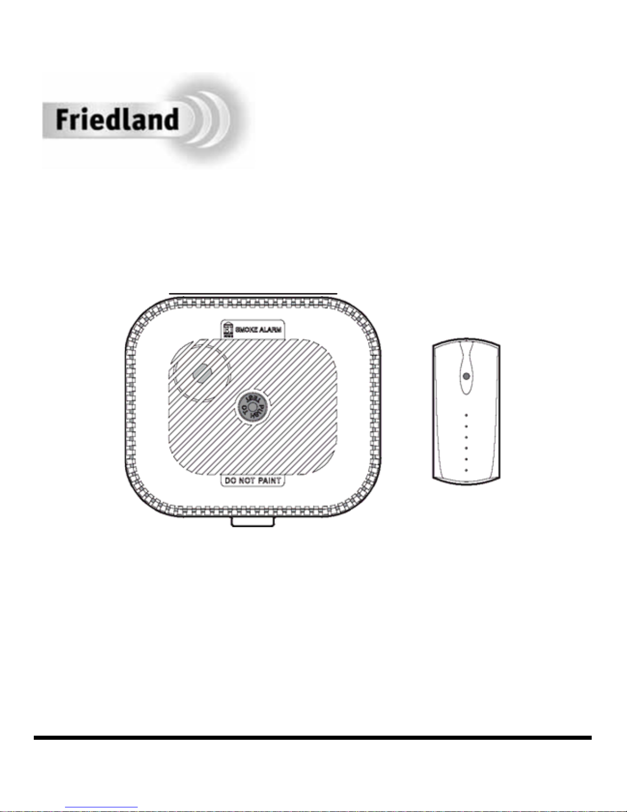
The Smoke Alarm and Interface
Module are suitable for mounting in
dry interior lo cat ions on ly.
The Smoke Alarm must be
positioned according to the
guidelines stated in its instruction
manual.
In addition, the Interface Module
must be mounted within the
specified radio range of 50m to the
Control Panel. Don’t forget to allow
for any obstructions in between that
may reduce this range. Take care
not to position the device directly
onto, behind or very close to
metalwork, as this could affect the
operating range of your system.
Note: If using the interconnect
feature on the smoke alarm then
only one Alarm Interface Module
should be connected to a single
Smoke Alarm only.
1 Wiref
ree Alarm Interface Module
CONFIGURING THE
INTERFACE MODULE AND
SMOKE ALARM
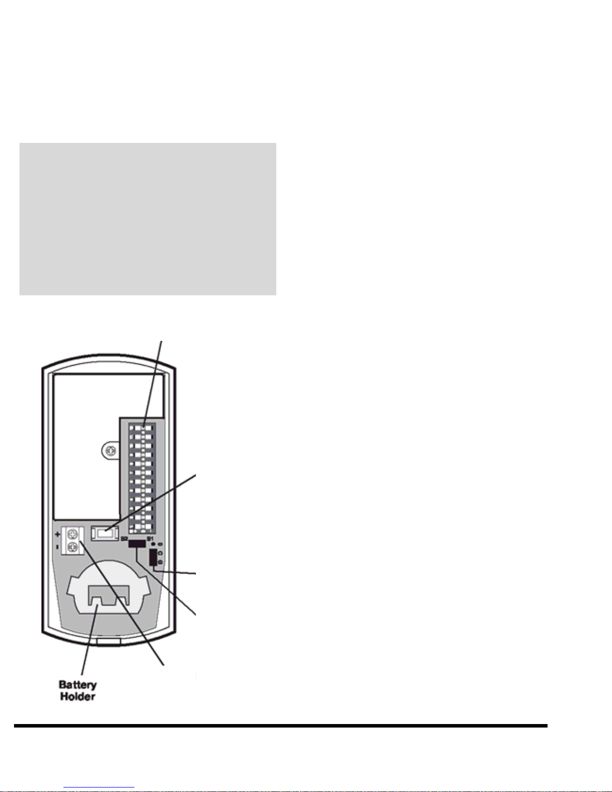
Configuration
Switches
Configuring the Interface
Module:
1) Remove the rear cover by
inserting a small coin between
the front and back covers and
gently twisting.
The procedures described in this
section should be undertaken
on a table to ensure that the
Interface Module and Smoke
A
larm are correctly setup and
operating before fixing the devices
in position on the ceiling.
Inside the Interface Module are
two jumper links and a series of
twelve 3-position switches.
These are used to configure the
device for use with the Smoke
Alarm and your alarm system.
2) Jumper link S1 must be
connected across pins marked
“G” and “C”.
Terminal
Block
Tamper
Switch
Jumper
S1
3 ) Jumper Link S2 must be fitted
in position across the pins.
4 ) Set switches 1-8 to the same
alarm system house code as
configured into all other alarm
system devices.
House Code Interface Remote Control
setting DIP switch DIP switch
+ 1 On / Up
-0 Off / Down
Jumper
S2
For example; an alarm system
house code of 1101 0011 will
Wirefree Alarm Interface Module 2