

FRIEDLAND VIS3121, VIS3222D, VIS3121D, VIS3222, VIS3322D Installation And Use Manual

g
d
n
Portable Visiocam LCD Video Chime System
Installation and use
Tragbares LCD-Videoglockenspielsystem
Installation und Gebrauch
Mobiel video-deurbelsysteem
Installatie en gebruik
Sistema di Videocamera
portatile a cristalli liquidi
Installazione e uso
i

English
Portable VisioCam LCD Video
Chime System
Installation and Use
Contents
Features ......................................................... 3
The VisioCam system.................................... 3
Checking pack contents................................ 3
Setting up ...................................................... 4
Pre-installation setup................................... 4
Installing the door camera ................................ 6
Door Camera Transformer option .................... 7
Installing the receiver ...................................... 8
Receiver Operation....................................... 8
Door camera ...............................................9
Expanding your system ................................... 10
Maintenance and use...................................... 11
Care and Maintenance ................................ 11
Replacing the receiver batteries................... 11
Troubleshooting ........................................ 12
Speci cations................................................ 13
Declaration............................................... 13
Disposal and Recycling ............................... 13
Guarantee ................................................ 12
This user guide applies to the following model numbers:
VIS3322, VIS3322D
VIS3121, VIS3121D
VIS3222, VIS3222D
VIS3x2x, VIS3x2xD
G-1
Portable VisioCam LCD Video Chime System –
Scan
VI
S
I
O
CA
M
Installation and Use
Thank you for choosing this Friedland product. Please carry out the following the instructions to ensure
correct installation and use, and keep these notes in a safe place for future reference.
Before you x the door camera or receiver in a permanent place, make sure that you have tested the two units
and that the system works in the location you have chosen! (See ‘Setting up’, beginning on the next page.)
Features
THE VI S IOCAM S YSTEM
Your Friedland wireless video entry system uses radio
signals to transmit a video picture of the caller from the
door camera to the receiver. The system is expandable,
so you can install additional surveillance cameras, or
a second door camera if required. The system is also
compatible with Friedland Evo and Friedland Décor door
chimes, so that you can install an additional wire-free
door chime in larger premises. See ‘Expanding Your
System’ on page 9 for more details.
Receiver features for use with future
products (available mid-2006):
■ Scan button – enables the receiver to scan CCTV
type cameras
■ Microphone volume – controls the audio level from
cameras with a tted microphone.
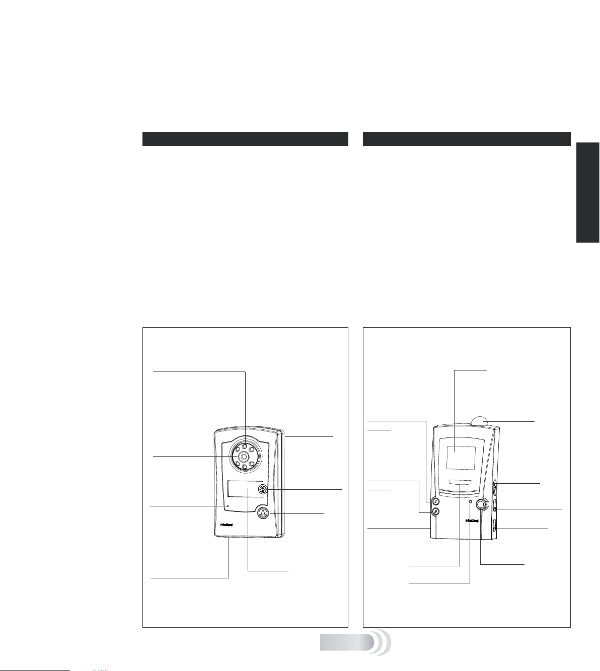
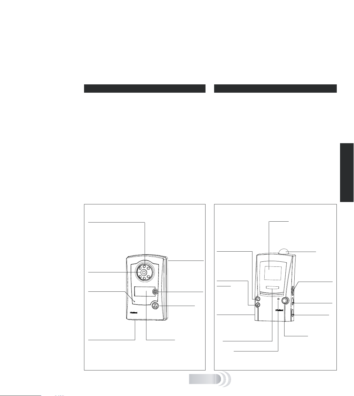
Door camera features Receiver features
Infrared LEDs
– allows the camera
to ‘see in the dark’ in
monochrome
Camera base
– removes for
Camera lens
– views callers
Condence light
– illuminates
when call button
is pressed to
reassure the caller
that the unit is
working
Light sensor
– detects ambient lighting
and switches camera from
colour to monochrome in
low light
Name plate
– for displaying
your name or
other information
wall mounting
Movement sensor
(PIR)
Call button
– activates the
chime tune and
camera
CHECKI N G PACK CONTENT S
The following items are included in the pack:
■ Door camera transmitter unit
■ Receiver unit with LCD display
■ Receiver charging base
■ AV SCART connection lead
■ Six No.8 screws for wall mounting
■ Six wall plugs.
You will need:
■ 6 x AA alkaline batteries for the door camera
■ A No. 2 crosshead screwdriver
■ A 6mm dia. masonry drill
■ A large at bladed screwdriver
Display
– screens the camera image
for approx. 30 seconds after
the call button is pressed
Tune selection
button
– selects the
chime tune for
the door camera
Tune selection
button
– for second
camera/push
AV socket
– to connect to
a TV set (optional)
Chime asher
Battery indicator
Antenna
– receives the
signal from the
camera
MIC volume
– for future use
Display brightness
Chime volume
Scan button
– looks for connected
CCTV-type cameras
[future Friedland
product]
English
G-2
English
PRE-IN S TALLAT I ON SETU P
Before xing the door camera in place, set up and test
the system as follows:
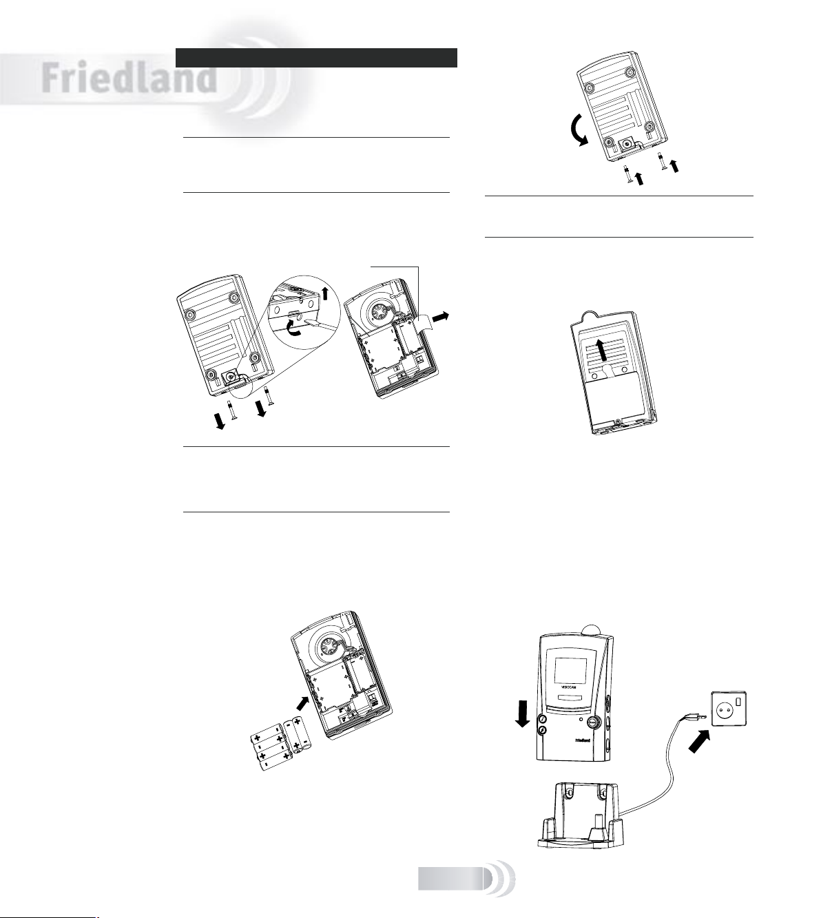
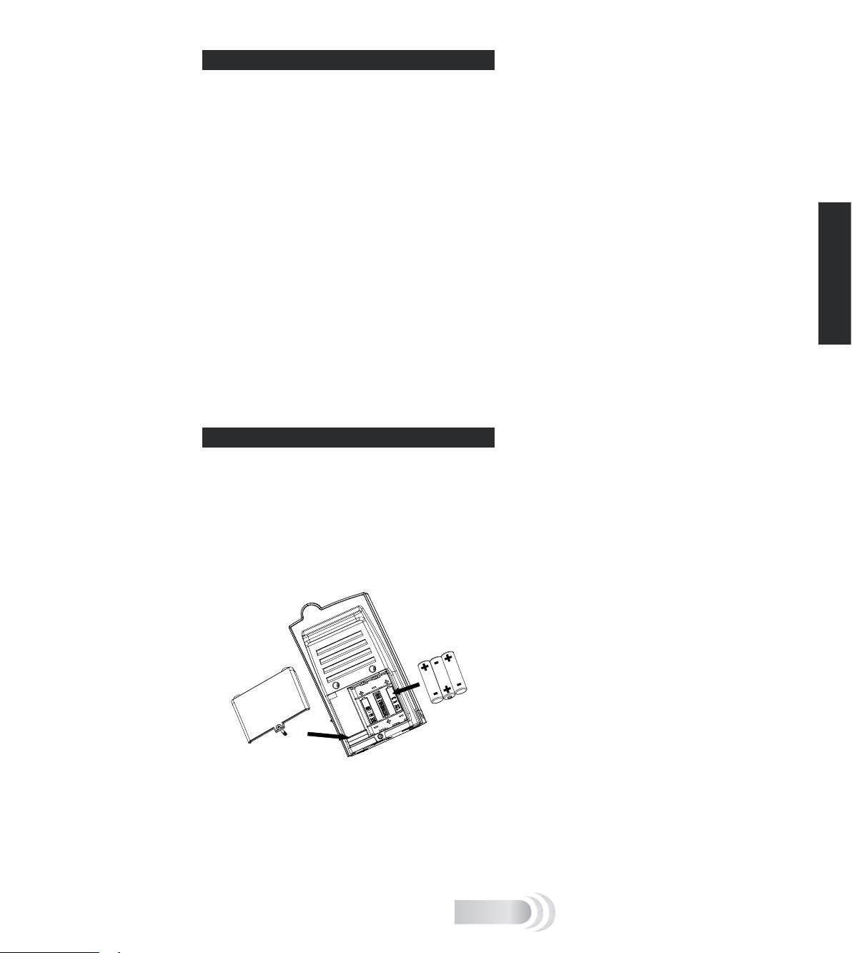
Install the batteries in the door camera
Note: The door camera has a built in tamper switch to help
prevent theft. Once the batteries have been inserted, the
con dence light ashes and the tamper alert sounds on the
receiver.
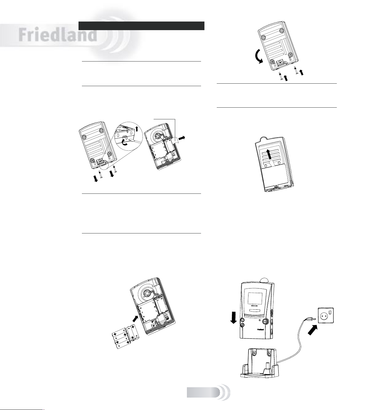
1. Remove the two screws at the base of the camera
unit and unhook and release the camera base,
pulling it away from the lower end rst.
Note: removing the cover also provides access to the
nameplate, so now is a good time to write your name or
other information. To use the nameplate, pull the end out
from the side of the battery compartment, add your text at
the end of the strip and carefully push it back into the slot.
2. Insert six AA-size alkaline batteries in the battery
compartment at the back of the door camera – as
in the following diagram. Follow the plus (+) and
minus (–) signs on the diagram inside the battery
compartment. Never mix old and new batteries.
3. Re t the camera base and insert the screws to stop
the tamper alert from sounding.
1
3
2
Note: there is an option to power the door camera using an
8V door chime transformer. See ‘Door Camera Transformer
option’ at the end of this section for details.
Charge the receiver batteries
1. Remove the battery isolating tab at the rear of the
portable receiver.
2. Place the receiver onto the charging base and plug
the charging base into a suitable mains socket.
The battery indicator ashes slowly if this is the rst
time the unit has been powered up; the chime tunes
play once the batteries have enough power.
Before the next step, leave the unit to charge for at
least three hours so that the batteries have enough
power for the LCD screen. The receiver takes about 12
hours to be fully charged.
Note that the charging base and rear of the receiver will
get warm in use: this is normal.
Setting up
G-3
Nameplate
English
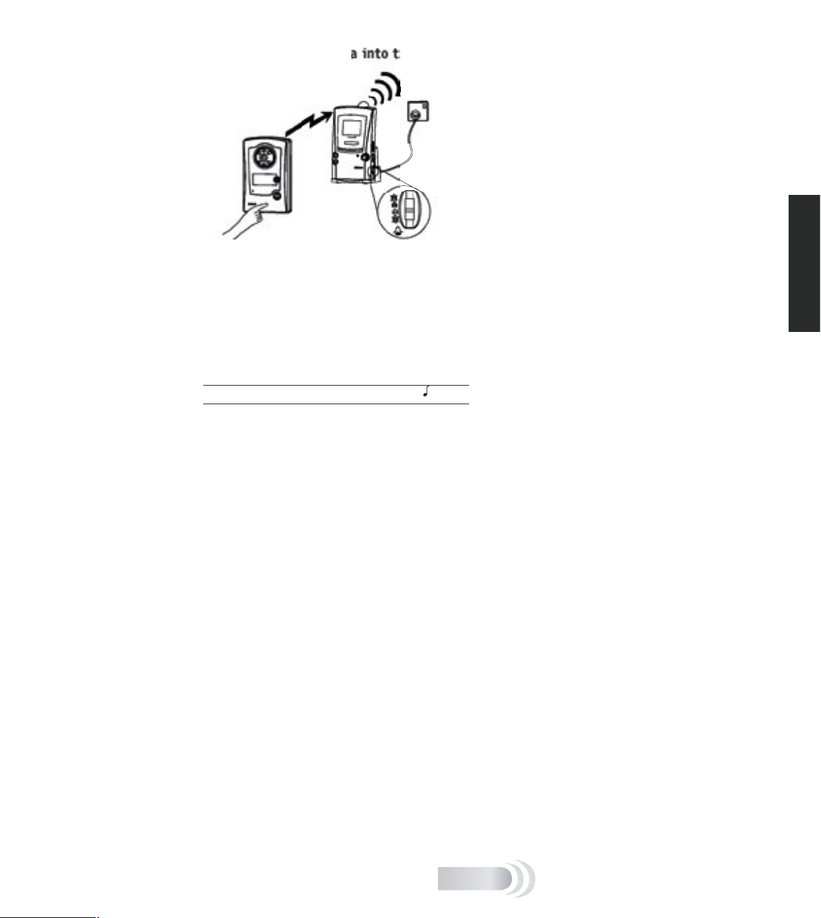
Program the door camera into the receiver
Ensure the door camera and receiver are separated by at
least 2m (6ft).
To program the door camera into the receiver, press
and hold the call button on the door camera until the
receiver responds with a tune and displays the image
captured by the camera.
Once the door camera has been programmed into the
receiver, the receiver remains active in program mode
for approximately two minutes.
Note: You can select another tune by pressing the ‘ ’ button.
G-4
English
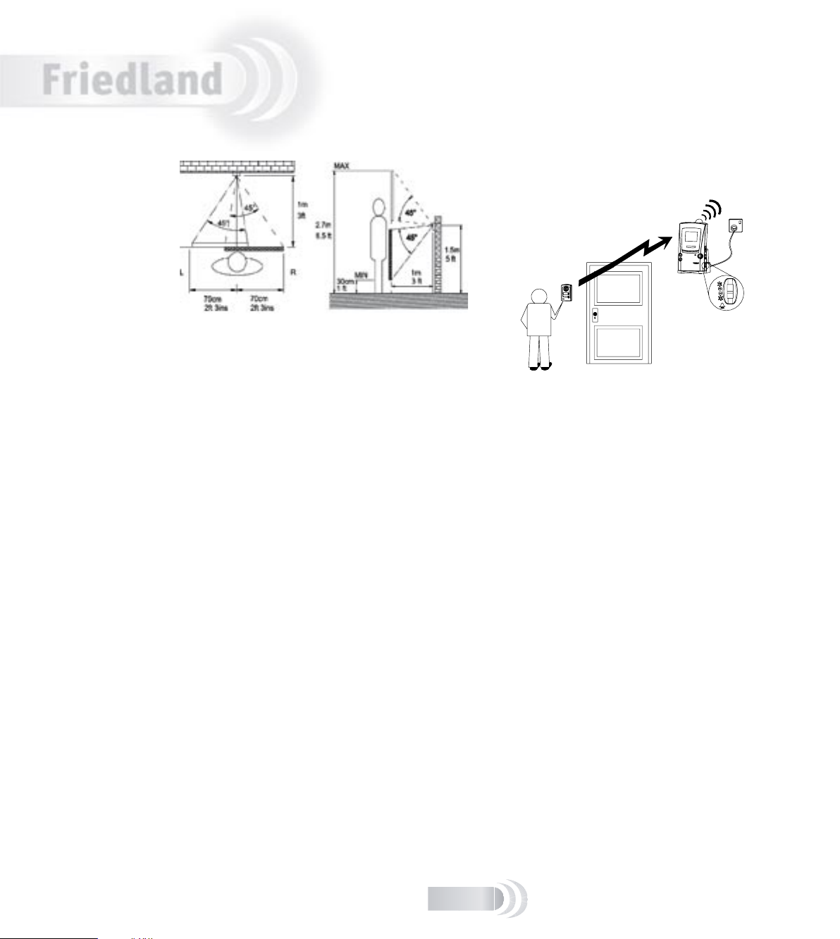
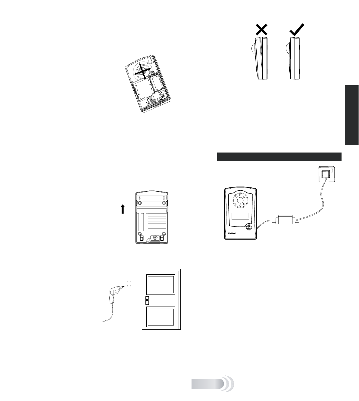
Installing the door camera
Position the door camera
Find a position for the door camera where the call
button is easy to press and the camera can ‘see’ visitors
clearly.
The following points are important:
■ The height needs to be between 1.3 and 1.5 metres
(4.5 to 5ft) above the ground or step where visitors
normally stand.
■ The camera is adjustable through a 30° total angle
left to right, and 60° top to bottom. Position the
unit to ensure the camera has sight of your visitor.
■ Avoid a position where the camera faces into the
sun, as this may overload the camera and visitors
will appear very dark. Facing large areas of bright
sky should also be avoided when possible by
pointing the camera down, rather than up.
■ Position the camera where the motion sensor is not
blocked from approaching visitors. Avoid locating
the camera where passing people or traf c will cause
false triggering. Note that the motion sensor range
is approximately 4m and that it can be switched off
if necessary (see ‘Door camera’, page 9).
■ The mounting surface should be of brick or wood
construction, and not of metal, reinforced concrete,
or heavy stone (i.e. more than 40cm thick)
construction – as this may block the transmitted
signal.
■ The mounting surface should be even and at, to
avoid distorting the door camera case, Level any
uneven surface before mounting, as a distorted base
can let rainwater into the unit.
■ Do not mount within 30cm of large metal objects, or
steel reinforced PVC frames, as this reduces or blocks
signals to the receiver.
■ Keep the base of the door camera clear of shelves or
other projections that might block the light sensor
under the unit. An obscured sensor causes the
camera to switch into black and white mode.
■ If the door camera is to be powered separately by
a bell transformer, then routing and xing of the
power cable must also be considered.
Position the receiver
The receiver must be positioned within range of the
door camera (i.e. less than 30m in a typical building).
Test the system
To ensure reliable operation, we recommend that both
the door camera and receiver are powered up in their
planned position(s), to check that the receiver has a
good signal from the door camera.
V
I
S
I
O
C
A
M
To test the system, have someone hold the door camera
against the wall in the selected mounting position and
press the call button, while you check the reception on
the receiver unit.
If the picture quality is poor, or there is no response
when the call button is pressed, then there are three
possible reasons:
1. The units may be too far apart (more than 30–40m
in a typical house). Try moving the receiver closer.
2. There is nearby interference on the video channel.
Remove the door camera back and change the video
channel switch from CH 1 to, for example, CH 3. Test
the system again, selecting a different channel if
channel 3 is no better.
Refer to the troubleshooting section for more
information on interference reduction.
3. The door camera has not been programmed into the
receiver (refer to page 4).
G-5
Horizontal
top view
Vertical
Adjust the camera angle
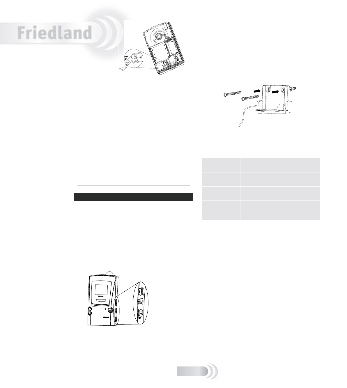
8V / 1A
With the door camera at the intended position, you
may need to adjust the camera lens to cover the desired
observation area.
Open the back of the door camera and adjust the camera
eyeball from the back of the product. Note that there is
more camera movement available in the Up/Down than
in the Left/Right direction.
4. Hook the door camera into the base at the top rst,
then push and click it in at the bottom. Check that
the unit is evenly pressed in place to seal the unit
from rain damage. Make sure that the sealing strip
on the camera front remains in place. Insert the two
screws underneath, and tighten.
Check that the unit is working after installation by
pressing the call button, the condence light should
illuminate.
English
Mount the Door camera
Do not mount the camera in wet conditions as moisture or
condensation will affect the internal parts.
Once you have tested the system in place, mount the
camera onto a wall or door as follows:
Top
1. Remove the two screws underneath the door camera.
Unhook and release the front and pull it away from
the base. Note the TOP arrow on the base.
2. If xing to a wall, mark the location of the
four mounting holes using the camera base
as a template. Drill using a 6mm masonry bit.
The distance between mounting holes is 72mm
horizontally and 92mm vertically.
3. Fix the door camera base in place using the screws
and wall plugs provided.
G-6
DOOR C A MERA T R ANSFORM E R OPTI O N
Transformer
For installations where there is frequent use, typically
more than ve uses per day, the door camera can
be powered using an 8 volt, 1 amp bell transformer.
Suitable Friedland transformer models are:
■ D753 (surface mount)
■ D780, D780S (DIN rail or surface mount)
Connect the low voltage output of the transformer to
the door camera using suitable low voltage cable such
as bell wire or telephone cable. Maximum recommended
outer cable diameter is 5mm. The cable run should not
exceed 30m (100ft).
A cable inlet with a water seal is provided in the rear of
the door camera. To connect up the transformer:
1. Feed the power cable through the cable inlet and
connect it to the power terminals. Leave about 15cm
(6 inches) of cable free between the base and the
door camera body, for later service access. Do not
t batteries.
English
2. Secure the door camera in place. Check that the
front is fully and evenly pressed in to seal the unit
against rain damage.
3. Secure the cable using clips or tacks as appropriate.
4. Connect the other end of the power cable to
the secondary (8V output) of an unpowered bell
transformer. Follow the transformer instructions
carefully for correct connections.
5. Connect the mains terminals of the transformer to a
suitable, always on, mains supply.
Test the door camera by pressing the call button: the
con dence light should illuminate.
Note: If you have not used the door camera with batteries for
a trial test, then you must program the door camera with the
receiver by following the ‘program the door camera into the
receiver’ instructions.
RECEIV E R OPER A TION
When the call button is pressed on the door camera, the
receiver chimes (provided the volume switch is not set
to 0) and the camera image is displayed for about thirty
seconds. If the caller presses the call button again,
then the display time will extend to another 30 seconds.
Video transmission is limited to 30 seconds to conserve
camera battery life and is not adjustable.
When the batteries need recharging, a camera image is
no longer shown – the chime alone sounds (unless the
battery level is too low for sound).
Charging base
Like a portable phone, keep the receiver topped up on
the charging base for reliable operation. Depending on
use, the receiver should operate for several days off the
charging base. The charging base can be used on a at
surface or xed to a wall using the supplied screws and
wall plugs. Before xing in place, check that the receiver
can pick up a good signal at the intended position.
Battery indicator
The indicator behaves as follows:
Remains on when the receiver is on the
charging base and is fully charged.
Blinks once a
second
when the receiver is charging.
Remains off when the receiver is off the charger
and the batteries are OK.
Blinks slowly
once every ten
seconds
when the receiver is off the
charging base and needs
recharging.
Chime asher
Flashes to indicate a call when the chime volume control
is in position 0 or 2*.
Display brightness
Activate the door camera by pressing its call button,
then adjust the receiver display for best viewing by
using the four position slide switch. One step down from
maximum brightness is the recommended setting.
Chime volume control
The chime volume level can be set to using the lowest
slide switch of the three (see diagram above). Adjust to
high level (2), low level (1), or off (0).
Installing the receiver
MIC volume [for
future use]
Display brightness
Chime volume
G-7
To the transformer

Chime tune selection
The receiver chime tune can be changed by pressing the
‘ ’ button.
Chime tune options are as follows:
■ Two note bell (Default tune for door camera)
■ Saxophone (Default tune for second door camera or
bell push)
■ Single note bell
■ Knock.
The ‘ ’ button changes the chime tune for a second
door camera or a door push
Night operation
In good daylight conditions, the receiver displays a
colour picture. In low lighting or at night the display
automatically switches to black and white. Infrared
LEDs illuminate the caller, so they can be viewed on the
receiver even when surrounded by complete darkness.
Low camera battery indication
When the batteries in the door camera are running low,
the receiver indicates this with a double beep warning
tone that follows the chime when a visitor presses the
call button. Replace the batteries in the door camera
within one week of a low battery alert.
DOOR C A MERA
Motion sensor
The PIR (‘Passive InfraRed’) sensor activates the
door camera automatically. The receiver produces a
‘ping’ sound and displays the door camera image for
approximately 30 seconds.
If the motion sensor is not required, then it can be
disabled.
To switch the motion sensor off, press and hold the call
button on the camera for more than ten seconds. The
condence indicator blinks rapidly to conrm that the
motion sensor is disabled.
To switch the motion sensor back on, press and hold the
call button for more than ten seconds, the condence
indicator remains on for two seconds to conrm.
Note: Power loss to the camera or a change of batteries will
reset the sensor back on.
English
Tamper alert tone
If someone attempts to remove the door camera by
unscrewing the cover screws, the tamper alert tone
is triggered, beeping for 30 seconds. Check outside
immediately.
Press any button on the front of the receiver to stop
the alert tone. The alert tone is unaffected by the chime
volume switch.
Note: The alert is also triggered when you undo the cover to
replace batteries in the door camera.
MIC volume
[For future use] The topmost control along the side
(see diagram) will control the volume produced from a
microphone. Adjust for optimum listening level.
Scan button
[For future use] When used in a multi-camera system,
this button scans through available pictures.
Privacy
Remember that this product uses the public airwaves,
and that the 30-second duration video signal from the
door camera(s) can be picked up by nearby 2.4GHz video
receiving devices.
G-8

English
There are many ways to expand your entry system:
you can connect your system to a television set or
add more cameras, for example.
TV connection
You can connect the receiver to a TV set via the
accessory SCART cable. The TV set must be equipped
with a SCART input.
When the door camera is activated, the receiver chimes
and the TV switches automatically to display the caller
on the TV.
Note: the automatic picture display is activated using the
TV SCART trigger mode. Some SCART sockets and some TV
sets will not work in this mode and you may need to change
channels manually. Refer to the TV set instructions for
advice.
Adding a door chime
The door camera can trigger one or more Friedland
Evo or Décor chimes in addition to the video receiver.
Additional chimes may be useful in large or noisy
premises.
Note: if you are using an existing chime, you will need to
clear it before it can be programmed to respond to the video
camera. To do this, press and hold in the two chime selection
buttons ‘A and B’ on the chime for around six seconds until
it starts playing its available tunes. The chime is now cleared.
To program the chime, make sure it is located within 8m
(25ft) of the door camera and press and hold the camera
call button until the chime sounds. The chime in now
programmed and ready for use.
Use the tune button on the chime to change the
tune if required. Refer to the chime instructions for
more detailed information. Note that a chime can be
programmed with a total of two door cameras or pushes.
Once programmed, the additional chime will respond to
the door camera call button, but not the tamper switch.
Note: If the wireless door push supplied with a chime is
not required, it can be used as an additional door push to
activate the video entry receiver – see below.
Adding a door push
The receiver will respond to a Friedland Evo or Décor
door push. To program a door push into the receiver:
1. Press and hold the ‘ ‘ button for approximately ve
seconds until the receiver beeps three times
2. Press the door push button until the receiver
sounds.
Note: The video receiver does not respond to a door push
while the video screen is active.
Expanding your system
Additional door cameras
The receiver will respond to up to four door cameras.
Each camera must be set on a different video channel
(1–4), and be programmed into the receiver. Refer to the
instructions provided with the additional unit, or see ‘To
reprogram or reset the receiver’, in this section.
Adding CCTV units
Compatible Friedland products (available from January
2006) will allow you to continuously view the outside
or inside of your premises. Programming is simple, as
with an additional door camera. Refer to the instructions
supplied with the add-on product for full details.
To reprogram or reset the receiver
A. To add another door camera, CCTV unit or bell
push:
Press and hold the ‘ ‘ button for more than ve
seconds, the unit will beep three times and enter
programming mode for approximately two minutes.
During the two minute programming time, press the call
button or button on the new unit to program it in. The
unit must be within 10–20m of the receiver to ensure
reliable programming.
B. To clear all programmed data, e.g. when replacing a
door camera:
Press and hold both the ‘ ’ and ‘ ‘ buttons in for
ve seconds to clear the programmed data and enter
programming mode. The available chime sounds play.
Follow the programming sequence under Receiver Setup.
G-9
CARE A N D MAIN T ENANCE
1
■ Fingerprints or dirt on the door camera lens can
cause a dull or blurred picture. Occasionally use a
soft, damp cloth to wipe the surface. Do not use
cleaning products. Over-zealous or too frequent
cleaning will scratch the surface and blur the
picture.
■ Keep the receiver and charger base away from rain,
liquids or risk of liquid spillage.
■ Do not place rings or other metal objects over the
peg in the charging unit – they will become hot to
the touch!
■ Do not allow any rain or damp to become trapped
inside the door camera, as it may damage the
internal parts.
■ Avoid replacing door camera batteries during wet
weather.
■ Do not take the products apart; there are precision
components inside which are easily damaged
■ Avoid dropping or strong shocks to either unit.
■ Only use the included or recommended power
supply.
■ Do not use or store either unit in dusty, dirty areas.
REPLAC I NG THE RECEIVE R BATTE R IES
Constant use will eventually reduce the capacity of the
rechargeable batteries, and reduce the receiver life off
the charger base. Replace the batteries by unscrewing
the single battery cover screw at the bottom rear of
the receiver. Remove the old batteries and replace with
three NiMh type AA batteries with a minimum capacity
of 1200mAH. Follow the battery orientation symbols in
the battery compartment. Replace the battery cover and
cover screw.
English
Maintenance and use
G-10

English
TROUBL E SHOOTI N G
The system does not work
■ Make sure the door camera is powered, refer to below
■ Make sure the receiver is powered, refer to below
■ Move the receiver closer to the door camera to
receive a better signal
■ If new, make sure the door camera is programmed to
the receiver – see ‘Pre-installation Setup’ on page 3.
Door camera is not powered
This is indicated when the red con dence light on the
front does not light when the call button is pressed.
Check;
■ The batteries are all inserted in the right direction
■ The batteries are new and Alkaline type
■ If transformer powered, the transformer is connected
to the mains and powered on
■ There is no damage to the transformer connecting
cable
■ The two wires in the transformer connecting cable
are making contact to the terminals in the unit and
in the transformer.
Receiver is not powered
■ The batteries are discharged. Place the receiver on
the charging unit for a minimum of 12 hours to
fully recharge the batteries. The receiver battery
indicator will blink once a second to indicate
charging, and will stay on when the receiver is fully
charged.
The receiver only displays a black and
white picture
■ The light level at the door camera is very low
■ The light sensor under the door camera is covered, is
too close to an adjacent object, or is facing a very
black surface.
The signal is poor, or there is interference
■ The receiver is in a signal ‘dead spot’. Rotate or
move the receiver 50cm and try again. People
walking near the receiver can also temporarily affect
the reception quality.
■ Make sure that the receiver is in range of the
door camera, approximately 30 meters in a typical
building. Move the receiver closer to see if the
picture improves. If this does not improve the
picture then there is nearby interference on the
video channel. Open the door camera and change
the video channel switch from 1 to 3, for example.
■ If there is more than one video transmitter (door
camera or others), every unit must have its video
channel switch set to a different channel.
G-11
■ A microwave oven may be in use in the path
between the door camera and receiver. Move the
microwave oven or turn it off.
■ Computers and other IT equipment can radiate
signals and affect the video quality. If this is a
likely problem, move the receiver away (at least one
metre) from the units.
The receiver chimes, followed by a beepbeep
This indicates low battery power in the door camera.
Replace the door camera batteries.
A beep-beep tone sounds for 30 seconds
This is an alert triggered by the tamper switch indicating
someone is trying to unscrew and remove the door
camera. Check outside immediately.
The tone may sound if the screws that x the front of
the door camera to the rear are not fully screwed in
place.
Press any button on the receiver to stop the alert tone.
The receiver switches on randomly
This is probably due to the motion sensor on the camera
picking up passers by, passing cars or moving heat
sources.
Switch the PIR sensor off, (refer to the ‘DOOR CAMERA’
section), block off the unwanted movement, or relocate
the door camera.
Chime sounds but the picture is displayed
for only a few seconds
■ The video signal has been interrupted. Press the
Scan button to recapture the video signal, move the
receiver to another position nearby.
■ If this occurs regularly, locate the receiver closer
to the door unit, or place the receiver higher up.
Generally, the receiver will receive a stronger signal
up on a shelf, and a weak signal near the oor.
■ The battery charge is low. Place the receiver on
the charger for at least four hours to recharge the
batteries.

Specications
Door Camera Receiver
Power requirement 230V AC ±10% via charger
Battery type 6 x AA-size alkaline batteries 3 x AA-size NiMH batteries,
Battery operating life typically one year * typically 3 days from full charge*
Motion sensor range 4m typical (xed sensitivity) N/A
Optional power via 8V AC 1A bell transformer**
Maximum number of transmitters
(video or door push) programmable
per receiver
Sound output N/A 80dBA/1m (position 2)
Operating frequency 433MHz and 2.4GHz 433MHz and 2.4GHz
RF output level <1mW, 10mW N/A
Antenna type (built in) omnidirectional omnidirectional
Camera type CMOS sensor
Effective resolution 628 x 582 pixels TFT LCD true colour display
Video standard PAL PAL
Settable Video channels 4 4, with auto detection
Video output N/A 1Vpp 75Ω
SCART trigger (to pin 8) N/A 12V (4:3 aspect picture)
Colour to B/W changeover Approx. 100 lux brightness
Operating temperature –10 to 40°C 0 to 40°C
Weight 340g (without batteries) 340g (with batteries)
Size H x W x D 160 x 97 x 49 mm 160 x 86 x 47 mm
IP rating IP55 IP3X; charging base IP44
or 8–12V AC or DC supply
N/A 6 (1, 2 with selectable chime tune;
minimum 1200mAh
N/A
3–6 with xed chime tune)
English
* Based on three calls per day in a temperate climate. More frequent use, or operation in a low temperature
environment (–10 to 5°C) will reduce battery life.
** Use Friedland transformer models: D753 (surface mount), D780, D780S (DIN rail surface mount)
DECLAR A TION
Friedland hereby declares that this wirefree product is
in compliance with the essential requirements and other
relevant provisions of the Radio and Telecommunications
Terminal Equipment (R&TTE) directive, 1999/5/EC.
GUARAN T EE
Friedland guarantees this product for one year from the
date of purchase. Proof of purchase is required; this does
not affect your statutory rights.
If you require further information about our product, call
the Friedland helpline on 01268 563066.
DISPOS A L AND R ECYCLIN G
Batteries and waste electrical products should not be
disposed of with household waste. Please recycle where
these facilities exist. Check with you local authority or
retailer for recycling advice.
© Friedland, 2005. E&OE
This product can be used without
restriction in all EU and EFTA countries.
G-12

Deutsch
Tragbares LCD-Videoglockenspielsystem
Installation und Gebrauch
Inhalt
Merkmale..................................................... D-2
Das VisioCam-System................................. D-2
Lieferumfang überprüfen............................ D-2
Einrichtung.................................................. D-3
Setup vor der Installation .......................... D-3
Installation der Türkamera .............................D-4
Türkamera Transformator-Option ................. D-6
Installation des Empfängers ...........................D-7
Empfängerbetrieb ..................................... D-7
Türkamera ...............................................D-8
Erweiterung Ihres Systems ............................. D-9
Wartung und Gebrauch ................................ D-10
P ege und Wartung ................................ D-10
Empfängerbatterien auswechseln .............. D-10
Fehlersuche ........................................... D-11
Spezi kationen........................................... D-12
Konformitätserklärung............................. D-12
Entsorgung und Recycling........................ D-12
Garantie................................................ D-12
Diese Betriebsanleitung gilt für folgende
Modellnummern:
VIS3322, VIS3322D
VIS3121, VIS3121D
VIS3222, VIS3222D
VIS3x2x, VIS3x2xD
D-1
Tragbares LCD-Videoglockenspielsystem –
Scan
VI
S
I
OCA
M
Installation und Gebrauch
Vielen Dank, dass Sie sich für dieses Friedland-Produkt entschieden haben. Führen Sie bitte die nachfolgenden
Anweisungen zur Sicherstellung von korrekter Installation und Gebrauch aus, und bewahren Sie diese
Betriebsanleitung für zukünftige Bezugnahme an einem sicheren Ort auf.
Bevor Sie Kamera oder Empfänger fest installieren, sollten Sie die beiden Geräte unbedingt testen um
sicherzustellen, dass das System an dem von Ihnen gewählten Installationsort funktioniert! (Siehe hierzu
„Einrichtung“, ab der nächsten Seite.)
DAS VI S IOCAM- S YSTEM
LIEFER U MFANG Ü BERPRÜF E N
Merkmale
Ihr schnurloses Friedland Video-Eingangsüberwachungssyst
em verwendet Funksignale zur Übertragung eines Videobilds
des Besuchers von der Türkamera zum Empfänger. Das
System ist erweiterbar, d. h. Sie können zusätzliche
Überwachungskameras oder, falls erforderlich, eine zweite
Türkamera installieren. Das System ist auch mit den
Friedland Evo und Décor Läutewerken kompatibel, sodass
Sie in größeren Gebäuden ein zusätzliches schnurloses
Läutewerk installieren können. Weitere Informationen
Zum Lieferumfang gehören:
■ Türkamera-Sender
■ Empfänger mit LCD-Display
■ Netzstromadapter
■ AV-SCART-Verbindungskabel
■ Sechs Schrauben Nr. 8 zur Wandmontage
■ Sechs Dübel
nden Sie auf Seite 9, „Erweiterung Ihres Systems“.
Empfängermerkmale zum Gebrauch mit
zukünftigen Produkten (ab Mitte 2006
erhältlich):
■ Scan-Taste – zum Abrufen der Bilder von Video-
übewachungskameras (CCTV) durch den Empfänger
■ Mikrofonlautstärke – reguliert die Lautstärke von
Sie benötigen:
■ 6 AA-Alkalibatterien für die Türkamera
■ Einen Kreuzschlitzdreher Nr. 2
■ Einen großen Schraubendreher mit acher Klinge
■ Ein Mauerbohrer-Bit, 6 mm
Deutsch
Kameras mit eingebautem Mikrofon.
Türkamera-Merkmale Empfängermerkmale
Infrarot-LEDs
- ermöglichen der
Kamera, im Dunkeln in
Schwarzweiß „zu sehen“
Kameraabdeckung
– wird zur WandKameralinse
– sieht Besucher
Kontrollleuchte
– leuchtet auf,
wenn der Klingelknopf gedrückt
wird und bestätigt
dem Besucher das
Funktionieren der
Einheit
Lichtsensor
– erfasst Außenlichtverhältnisse und schaltet die
Kamera bei schwachem Licht
von Farb- auf SchwarzweißWiedergabe um
Namensschild
– zur Angabe Ihres
Namens oder anderer
Informationen
montage entfernt
Bewegungsmelder
(PIR)
Klingelknopf
– aktiviert den
Klingelton und
die Kamera
Melodie-Wahlschalter
-wählt die
Klingelmelodie
für die Türkamera
MelodieWahlschalter
– für zweite
Kamera/
Klingelknopf
AV-Buchse
– zum Anschluss an
ein Fernsehgerät
(optional)
Blinkende Klingelanzeige
Batteriestandsanzeige
Display
– zeigt nach Betätigen des
Klingelknopfes ca. 30 Sekunden
lang das Kamerabild
Antenne
– empfängt das
Signal der Kamera
Mikrofonlautstärke
– für zukünftigen
Gebrauch
Display-Helligkeit
Klingellautstärke
Scan-Taste
– sucht angeschlossene
CCTV-Kameras
[zukünftiges Friedland
Produkt]
D-2
Deutsch
SETUP V OR DER INSTALL A TION
Vor der Installation der Türkamera sollte das System wie
folgt eingerichtet und getestet werden:
Die Batterien in die Türkamera installieren
Hinweis: Die Türkamera besitzt einen eingebauten
Manipulationsschutz zur Diebstahlverhütung. Sobald die
Batterien eingelegt sind, blinkt die Kontrollleuchte und der
Manipulationsalarm im Empfänger ertönt.
1. Die beiden Schrauben unten an der
Kameraabdeckung entfernen. Die Abdeckung
aushaken und abnehmen, wobei sie zuerst am
unteren Ende weggezogen wird.
Hinweis: Das Entfernen der Abdeckung gewährt auch Zugriff
auf das Namensschild. Somit kann es jetzt mit Ihrem
Namen oder anderen Informationen beschriftet werden.
Das Namensschild an der Seite des Batteriefach fassen und
herausziehen. Das Streifenende mit Ihrem Text beschriften
und den Streifen dann vorsichtig wieder in den Schlitz
schieben.
2. Sechs AA-Alkalibatterien in das Batteriefach
auf der Rückseite der Türkamera einlegen (siehe
Abbildung unten). Orientieren Sie sich an den
im dem Batteriefach angegebenen Plus- (+) und
Minuszeichen (-). Niemals alte und neue Batterien
zusammen verwenden.
3. Die Kameraabdeckung wieder anbringen und die
Schrauben wieder einsetzen und festziehen, um den
Manipulationsalarm abzuschalten.
1
3
2
Hinweis: Die Türkamera kann auch mit einem 8VTürklingeltransformator mit Strom gespeist werden. Weitere
Informationen nden Sie unter „Türkamera TransformatorOption“ am Ende dieses Abschnitts.
Empfängerbatterien au aden
1. Batterie-Isolierband auf der Rückseite des tragbaren
Empfängers entfernen.
2. Den Empfänger auf die Ladestation setzen und diese
an eine geeignete Netzstromsteckdose anschließen.
Die Batteriestandsanzeige blinkt beim ersten Au aden
des Geräts langsam auf; sobald die Batterien ausreichend
aufgeladen sind, ertönen die Klingelmelodien einmal.
Vor dem nächsten Schritt das Gerät mindestens drei
Stunden in der Ladestation lassen, damit sich die
Batterien für die LCD-Anzeige ausreichend au aden. Der
vollständige Ladevorgang dauert ca. 12 Stunden.
Bitte beachten Sie, dass sich die Ladestation und
Rückseite des Empfängers beim Gebrauch erwärmen: Dies
ist normal.
Einrichtung
D-3
Nameplate
 Loading...