

FRIEDLAND Spectra Plus L420N WHI, Spectra Plus L420N BLK, Spectra Plus L420S WHI, Spectra Plus L420S BLK Instruction Manual
D
ENG
1-12
Instruction Manual
13-26
Bedienungsanleitung
NL
27-40
Gebruiksaanwijzing
S
53-64
Instruktionsanvisning
DAN
41-52
brugervejledning
FIN
78-89
Ohjekirja
POL
65-77
Instrukcja obsługi
RUS
90-103
Инструкция по эксплуатации
PLUS
L420N WHI and L420N BLK
51002PL_Ed2
ENG
Before starting any
installation work,
please read carefully
L420N WHI and L420N BLK
Instruction Manual
and Guarantee
Your Spectra Plus Wirefree Passive
Infrared (PIR) Movement Detector and
Switching Receiver provides you with the
ability to convert any standard exterior light
fitting to an automatic movement activated
system. A built in Dusk/Dawn sensor can
be adjusted to prevent movement from
activating the light during daylight and to set
the level of darkness when the light will be
activated by detected movement. Both the
PIR Detector and the Switching Receiver
Unit are suitable for mounting outdoors.
No Wires! - There is no physical wiring
connection between the PIR and Receiver.
Instead the system uses radio technology to
provide the link which makes installation
even quicker and allows the PIR to be located
remotely at the most appropriate position
for the area being monitored. To prevent
interference from other devices the PIR
detector is coded with a unique identification
code that is already learnt into the Receiver
to make installation even quicker.
The PIR and Receiver are also compatible
with Friedland Libra Plus Chimes system,
(Chimes and Pushes).
Introduction
1

SAFETY
Always follow the manufacturers advice when using power tools; steps, ladders etc. and
wear suitable protective equipment (e.g. safety goggles) when drilling holes etc.
Before drilling holes in walls, check for hidden electricity cables and water pipes,
the use of a cable/pipe locater maybe advisable if in doubt.
The mains supply to this product should be installed by a competent person
(e.g. a qualified electrician) in accordance with these instructions and in accordance with
the appropriate clauses of the current edition of the IEEE wiring regulations (BS7671).
It is essential that all connections are made as instructed, that cables are not stressed
and that terminals are fully tightened.
DANGER - 230 VOLTS. To prevent the risk of electrocution, always turn off the mains
electricity supply before commencing any work on the installation or opening the receiver.
Do not attempt to install or program this product while it is wet or raining.
TOOLS REQUIRED
● No.2 Philips Screwdriver
●
3mm flat bladed screwdriver
● Drill
● 6mm Masonry drill bit
● Wire Cutter and Strippers
2
The quoted range of the system is measured
in ideal conditions. Any barrier (e.g.
walls/ceilings aluminium reinforced UPVC
windows and metallic parts of house
structures etc) between the PIR and receiver
will reduce the effective radio range by an
amount dependant upon the construction of
and number of barriers between the PIR (MP)
and receiver. In extreme cases where metal
barriers are involved then it is possible for the
signal to be blocked out completely .
Whilst the majority of installations are not
adversely affected, you may have to
experiment a little to discover the best
location for your PIR and Receiver Unit.
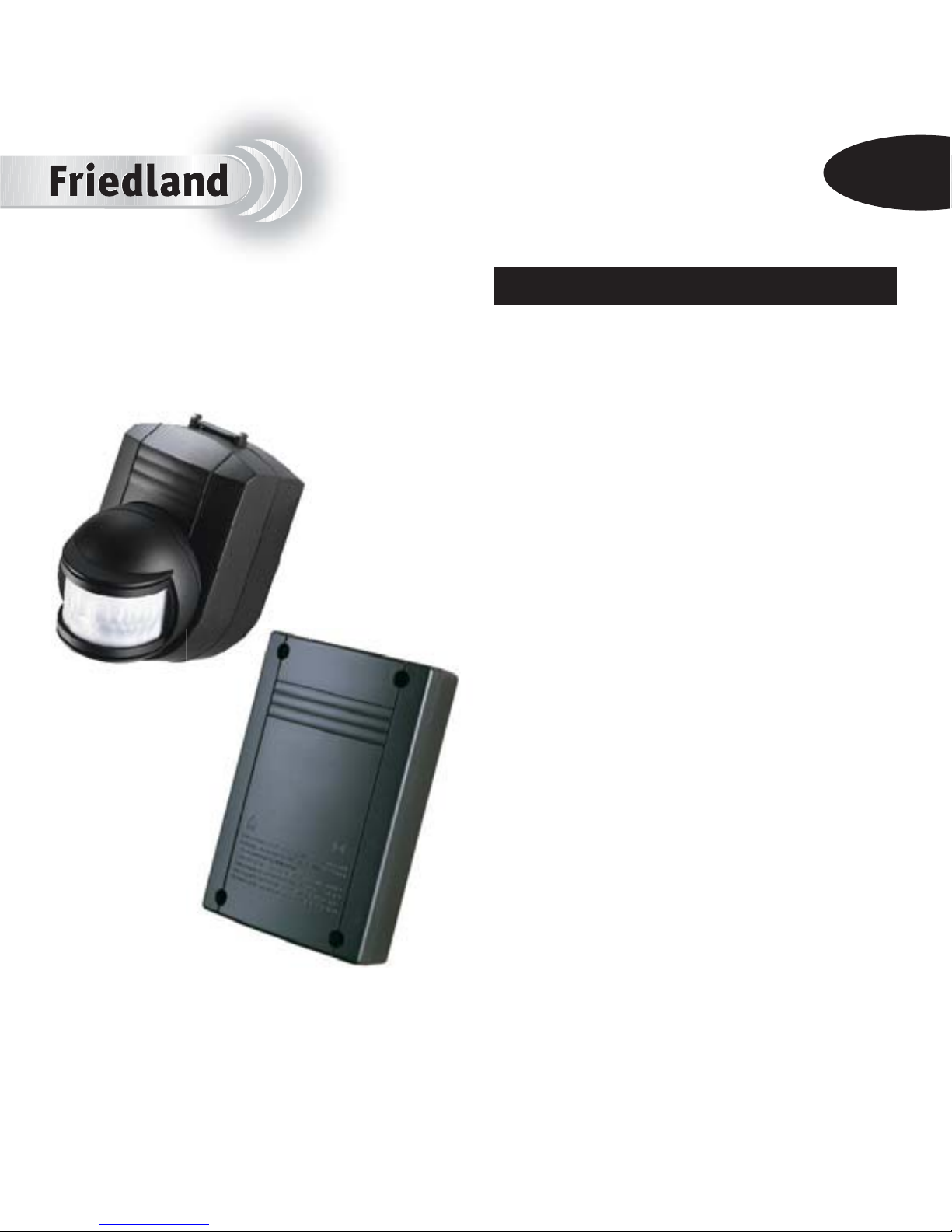
KIT CONTENTS
PIR Detector
Switching Receiver
Instruction Manual
Fixing pack c ontaining:
●
2 slot-in PIR window masking curtains
● 4 fixing screws and plastic wall plugs
● 2 fixing screw sealing plugs
You will also need
● One 9V PP3 (6LR61) Alkaline Battery
Device range
4
2
3
1
A
B
3
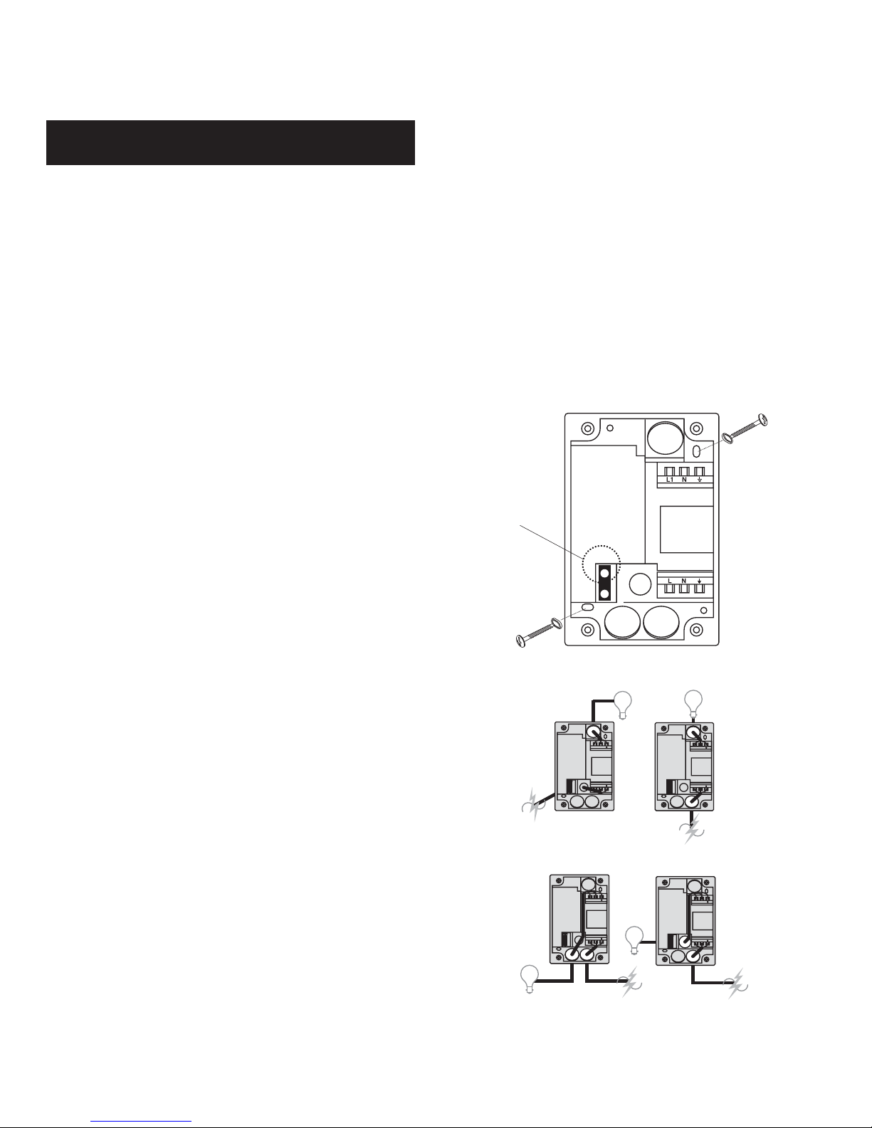
Installing the Receiver
Positioning the Receiver
The Receiver has been designed so that it
can be fitted to the wiring of an existing
light fitting without the need to rewire. The
cable is cut at a convenient point and the
receiver connected to the cut cable ends.
However, with this approach you can only
use the top and bottom cable entry holes
closest to terminals A and B ensuring that
the supply cable is connected to Terminals
A and the cable from the lights is connected
to Terminals B.
Important: the mains supply to existing
wiring must be disconnected and isolated
before installing in this way.
When selecting a position for the receiver
the following points should be taken into
consideration:
● The product should only be mounted on
a sound flat surface in a vertical position,
(it should not be mounted horizontally).
● The 220-240Vac 50Hz electricity supply
cable must be connected to terminals A.
● The cable to the light fitting must be
connected to terminals B.
● The top cable entry point hole next to
terminals B cannot be used for the
power supply cable.
● Only one cable (up to 14mm diameter)
may be fitted through each cable
grommet. The receiver unit is not
designed for direct connection to conduit.
LN
L1 N
AB
4
LN
L1 N
A
B
1
4
LN
L1 N
A
B
21
4
LN
L1 N
A
B
Receiver
Testing the Receiver
The Receiver has a built in Test/Manual
operation facility which can be operated by
pressing the Learn button for under 1 second.
If the lights are OFF, they will be switched on
for a period of 5 seconds.
If the lights are already ON, pressing the
learn button will cancel any remaining time on
period and immediately switch them OFF .
Test
button
 Loading...