

FRIEDLAND SPECTRA Lite Instruction Manual
Lite
3
List Number L110N WHI
BEFORE STARTING ANY INSTALLATION WORK, PLEASE READ CAREFULLY
TOOLS NEEDED
● Drill and 6mm Masonry Drill Bit
●
Wire cutters and Wire Strippers
● No.2 philips Screwdriver
● Terminal or Electricians Screwdriver
● Large Flat Bladed screwdriver
PARTS INCLUDED
- Bulkhead PIR light
- Instruction Manual
- Accessory pack
Instruction Manual
SAFETY
Always follow the manufacturers advice when using power tools, steps, ladders etc. and wear suitable
protective equipment (e.g. safety goggles when drilling holes). Before drilling holes in walls, check forhidden
electricity cables and water pipes, the use of a cable/pipe locater maybe advisable if in doubt.
The mains supply to this product should be installed by a competent person (e.g. a qualified electrician) in
accordance with these instructions and in accordance with the appropriate clauses of the current edition of
the IEEE wiring regulations (BS7671).
DANGER - 230 VOLTS. To prevent the risk of electrocution, always turn off the mains electricity supply
before commencing any work on the installation or opening the detector.
It is essential that all connections are made as instructed, that cables are not stressed and that terminals
are fully tightened.
Suitable for connection to fixed luminaires only. Internal and connected lamps loads must not exceed the
specified maximums. This product is suitable for wall mounting only.
Eng
1
Fig. 3
Fig. 2
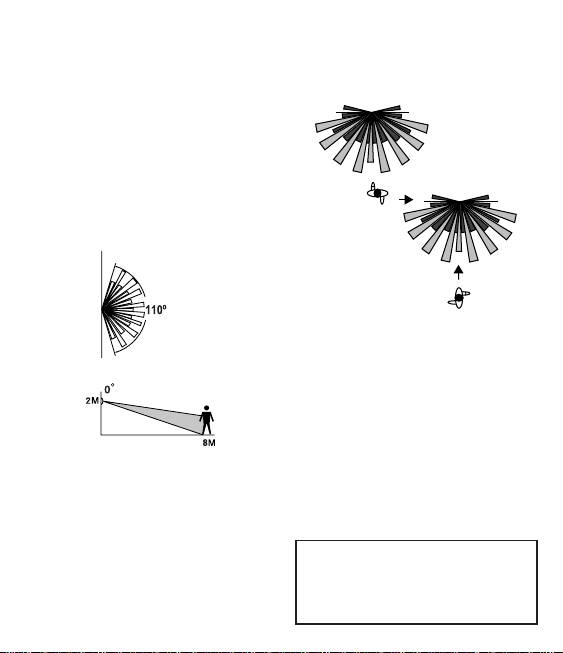
ACROSS its field of vision [Fig. 2], rather
than movement directly toward it [Fig. 3] so if possible, mount the PIR facing
ACROSS the approach to your property.
After choosing a suitable location (see
previous section) install the unit as follows:
The unit is suitable for connection to a 230V
AC 50Hz electricity supply. It is suggested that
3-core round flexible cable of 1mm
2
gauge
is used. A double pole switch should be
installed to switch the power to the unit ON
& OFF. This allows the detector to be easily
switched off when not required or for
maintenance purposes.
MOUNTING, WIRING
2& CONNECTION
IMPORTANT
Switch off the electricity at the fuse box by
removing the relevant fuse or switching off
the circuit breaker before proceeding with
the installation
SELECTING A
1LOCATION
Fig. 1
Your PIR Detector has a number of
detection zones at various horizontal and
vertical angles, as shown. A moving human
body crossing or entering one of the zones
activates the Detector. Mount the Detector
at a height of 2m for the best all-round
coverage [Fig. 1] - it may be positioned up
to 4m high for a greater detection range,
but the detection pattern will be less
effective.
Careful positioning of the tilt and swivel
Detector head is needed to ensure optimum
performance. When performing the WALK
TEST [Section 3], the angle of the head
may require slight adjustment, particularly
when mounting your PIR Detector higher
than the recommended 2m.
Also note that the PIR Detector is
much more sensitive to movement
2
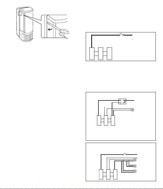
Remove the diffuser using a flat bladed
screwdriver to release the clips on both sides
(Fig 4).
Detach the connection cover by removing
the fixing screw.
Ensure the unit is in an upright position with
the sensor module at the bottom.
Mark the position of the fitting holes.
Drill the holes. Insert the wall plugs into the
holes.
PIERCE & PASS THE CABLE THROUGH
THE GROMMET BEFORE PROCEEDING
Secure the unit to the wall using screws
provided. Do not overtighten the screws as
this could damage the unit.
CONNECTION
Pass the mains supply cable around the
back of the lampholder for ease of wiring.
Connect the cable to the terminal block on
the unit as follows (see connection diagram):
NEUTRAL (Blue) N
LIVE (Brown) L
Note: the unused earth wire mut be insulated
and placed in the termination area.
For class 1 lights in series with the switched
output of the lamp make sure that the earth
continuity to the lights is provided, use
external junction boxes, if necessary.
Ensure that the connections are secure.
Re-attach the connection cover.
Install the lightbulb (not supplied).
Fit the diffuser back onto the main body of
the unit, ensuring it clicks firmly in place
YOU CAN CONNECT ADDITIONAL LIGHT
UNITS TO SPECTRA LITE.
The PIR detector will control the additional
light as well as the built in lamp. Ensure the
total wattage of lamps connected does not
exceed the maximum switchable load.
Fig 4
LN
L1
LIVE
NEUTRAL
Indoor switch
for permanent
off override
(optional)
LN
L1
LN
L1
LIVE
NEUTRAL
LIVE
NEUTRAL
Single pole 2 gang switch
Lamp
PERMANENT OFF: S1 OPEN S2 OPEN
AUTO MODE: S1 CLOSED S2 OPEN
PERMANENT ON: S1 OPEN OR CLOSED S2 CLOSED
Indoor switch for permanent
off override (optional)
Lamp
Lamp
Lamp
 Loading...