

FRIEDLAND Bronze, Silver Installation & Operating Manual
0
1 2 3
4 5 6
7 8 9
2
1
Friedland
™
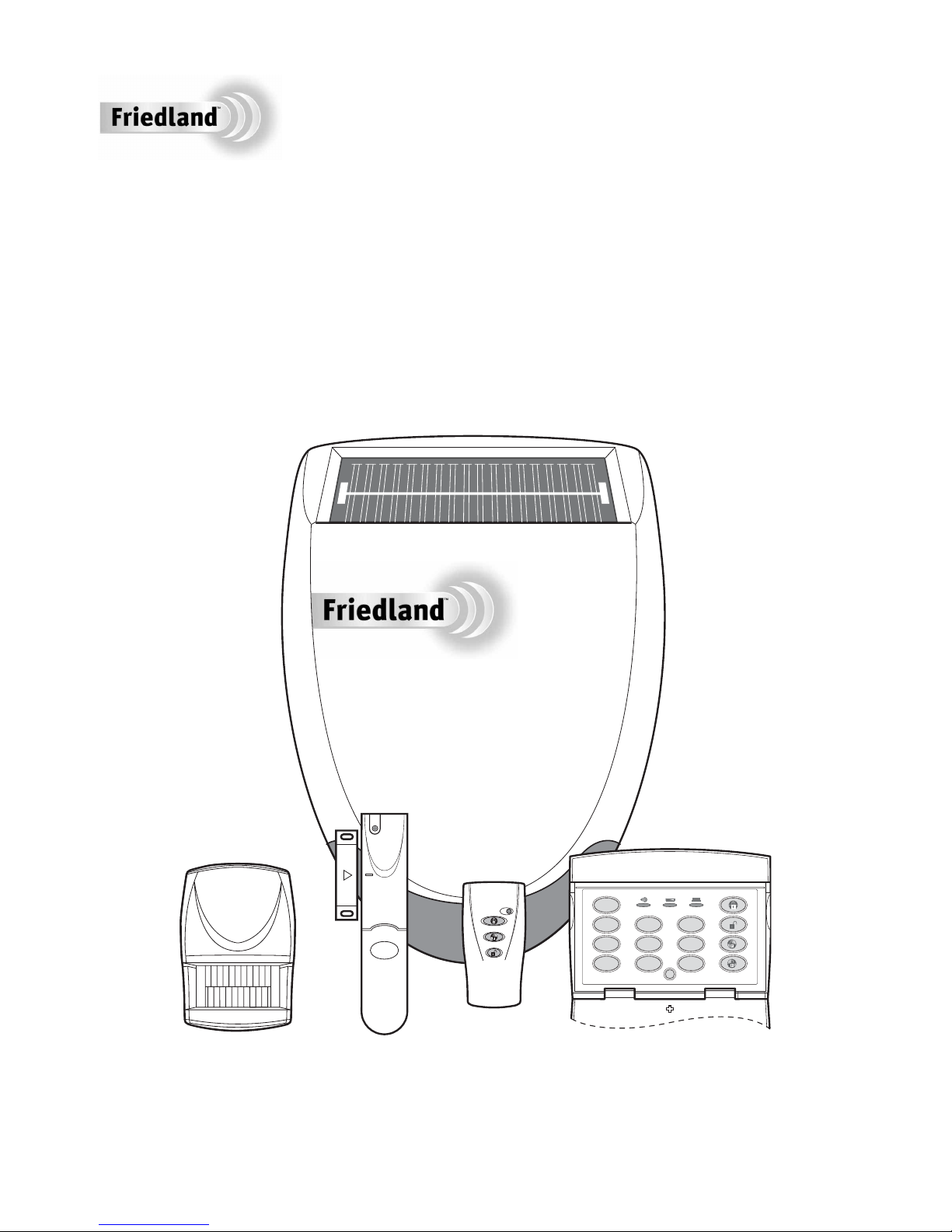
Wirefree Security Alarm
Bronze / Silver
Installation & Operating Manual

FOREWORD
All devices in this Wirefree Alarm System are
designed and manufactured to provide long reliable
service. The system is designed for ease of
installation using only conventional domestic tools.
However, it is essential that the installer reads and
fully understands the advice and procedures
contained in this manual and plans the system before
proceeding with the installation.
During installation, it is important that the procedures
described in this manual are followed in sequence.
This manual should be retained in a safe place
for future reference.
IMPORTANT: All devices, with the exception of the
External Siren are suitable for mounting in dry
interior locations only.
DECLARATION
Novar ED&S hereby declares that this wirefree alarm
system is in compliance with the essential
requirements and other relevant provisions of the
Radio and Telecommunications Terminal Equipment
(R&TTE) directive, 1999/5/EC.
DEVICE RANGE
The quoted range of the system devices (see
component
specification on rear cover) is measured
in ideal conditions. Any solid object (e.g. walls,
ceilings,
reinforced PVC doors etc) placed between
the transmitter and Receiver device will reduce the
radio range.
The amount by which the range will be reduced is
dependant upon the nature of the barrier.
For example:
Wall Type Range Reduction
Dry-lined partition wall: 10 - 30%
Single layer brick wall: 20 - 40%
Double layer brick wall: 30 - 70%
Metal panel/radiator: 90 - 100%
Note: The effect on the range of multiple walls is
cumulative, i.e. if there are 2 brick walls in the way,
the range will be reduced by up to 40% by each wall.
SYSTEM SECURITY
This system has been designed to both detect
intruders and act as a strong deterrent to would-be
intruders when installed correctly.
We recommend that your Alarm is used in conjunction
with good physical protection such as security window
and door locks.
All units in the system are encoded to operate together
using a 20 bit House Code.
The system is operated from one or more Remote
Control Units and/or Keypads.
SAFETY
Always follow the manufacturers advice when using
power tools; steps, ladders etc. and wear suitable
protective equipment (e.g. safety goggles) when
drilling holes etc.
Before drilling holes in walls, check for hidden
electricity cables and water pipes, the use of a
cable/pipe locater maybe advisable if in doubt.
When using ladders, ensure that they are positioned
on a firm stable surface at the correct angle and
suitably secured before use.
The use of ear defenders is advisable when working
in close proximity to the Siren due to the high sound
level produced by this device.
2
IMPORTANT:
LOCAL AUTHORITY REGULATIONS AND
LEGISLATION
This alarm system should be installed and
operated in accordance with the requirements of
any current local and/ or national regulations and
legislation. We recommend that you contact your
authority to obtain details of your area's
requirements regarding intruder alarm installations.
Tools and Equipment Required:
No.0 Philips Screwdriver Bradawl
No.1 Philips Screwdriver Drill
No.2 Philips Screwdriver 3mm Drill Bit
Small Spirit Level 5 & 6mm Masonry Drill Bits

3
CONTENTS
KIT CONTENTS 4
INTRODUCTION AND OVERVIEW 5
System Arming 5
Entry/Exit Delay 5
Alarm Lockout 5
Tamper Protection 5
Jamming Detection 5
Battery Monitoring 5
User Access Code 5
PLANNING AND EXTENDING YOUR
ALARM SYSTEM 6
Typical Installation 6
REMOTE CONTROL UNIT 7
General Information 7
Configuring the Remote Control 7
Testing the Remote Control 7
KEYPAD 7
Positioning the Keypad 8
Installing and Configuring the Keypad 8
Changing the User Access Code 9
Personal Attack /PA 9
Resetting to Factory Defaults 9
EXTERNAL SOLAR SIREN 10
General Information 10
Positioning the Solar Siren 10
Installing and Configuring the Solar Siren 10
Power-up of the Solar Siren 11
Adding a new Remote Control or Keypad
to the Solar Siren 12
Mounting the Solar Siren on to the wall 13
PASSIVE INFRA-RED (PIR) MOVEMENT
DETECTORS 13
Positioning the PIR Detectors 13
Installing and Configuring the PIR Detectors 14
Testing the PIR Detectors 15
MAGNETIC CONTACT DETECTORS 16
Positioning the Magnetic Contact Detectors 16
Installing and Configuring the Magnetic
Contact Detectors 16
Testing the Magnetic Contact Detectors 18
ADDING A NEW PIR OR MAGNETIC (MAG)
DOOR / WINDOW CONTACT DETECTOR
TO THE SIREN 18
DELETING ALL DEVICES FROM
THE SYSTEM 19
SIREN SERVICE/OPERATING MODE 19
TESTING THE SYSTEM 20
OPERATING INSTRUCTIONS 21
Arming the System in Instant-Arm Mode 21
Arming the System in Delay-Arm Mode 21
Disarming the System 22
Personal Attack (PA) Alarm 22
Device Tamper 22
Siren Service Mode 22
Siren Operating Mode 22
Battery Monitoring 22
MAINTENANCE 24
TROUBLE SHOOTING 25
EXTENDING YOUR ALARM SYSTEM 27
COMPONENT SPECIFICATION 28
4
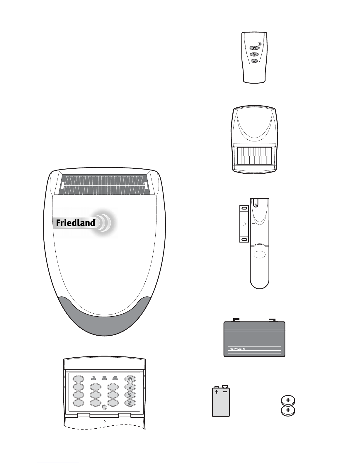
KIT CONTENTS
The Alarm System should contain the following devices.
Alarm System SK1 Bronze SK2 Silver
Solar Siren 1 1
Remote Control 1 1
PIR Movement Detectors 2 2
Magnetic Contact Detectors 0 2
Keypad 0 1
Also included:
Siren Mounting Template
Installation & Operating Manual
Installation DVD
Fixing Pack
Batteries
Solar Siren
PIR Movement Detector
Friedland
™
Magnetic Contact Detector
6V/1.2Ahr Sealed lead acid battery
(supplied fitted in Siren)
3V CR2032 Lithium Coin Cell
(for Remote Control and
Magnetic Contact Detectors)
9V PP3 Alkaline battery
(for Siren, Keypad and
PIR Detectors)
Remote Control
Keypad
0
1 2 3
4 5 6
7 8 9
2
1

5
SYSTEM ARMING
The system has an Instant-Arm and Delay-Arm mode.
If the system is armed in Instant-Arm mode then all
detectors will immediately become fully armed. Any
detector triggered while the system is armed will
immediately sound an alarm.
ENTRY/EXIT DELAY
If the system is armed in Delay-Arm mode this will
activate the system with a fixed 15 second entry/exit
delay period. This allows a 15 second period for the
user to exit the property after setting the system with
the Remote Control or at the Keypad. Any detector
triggered while the system is armed will not cause an
alarm condition until after the 15 second entry delay
has expired. This allows time for the system to be
Disarmed before an alarm sounds when re-entering
the property.
Note: To conserve power and maximise battery life
the PIR Detector will only detect movement if there
has been no movement detected within the previous
2 minutes. Consequently the PIR Detector will not
become active until the protected area has been free
from movement for more than 2 minutes.
ALARM LOCKOUT
If a detector is triggered while the system is armed,
the alarm will sound. After the set alarm duration
has ended, the alarm will stop and the system will
automatically reset. Subsequent detectors triggered
will again sound the alarm. If the alarm is triggered
more than 3 times then it will become ‘Locked Out’
and any further alarm signals will be ignored until the
system is re-armed.
TAMPER PROTECTION
All system devices (except the Remote Control)
incorporate Tamper protection features to protect
against unauthorised attempts to interfere with
the device.
Any attempt to remove the battery cover from any
device (except a Remote Control) or to remove the
Siren from the wall will trigger an alarm (unless the
system is in Service Mode), even if the system is
Disarmed.
JAMMING DETECTION
In order to detect any attempts to illegally jam the
radio channel used by your alarm system, a special
jamming detection function is incorporated into the
Siren. If this feature is enabled, an alarm will be
triggered if the radio channel is jammed continuously
for more than 30 seconds or if the system is jammed
for more than 3 periods of 10 seconds in a 5 minute
period. (The Siren will emit a series of rapid beeps
as a pre-alarm warning 10 seconds before a full
alarm occurs).
The jamming detection circuit will constantly scan for
jamming signals. However, it will also detect and
could in extreme cases be triggered by radio signals
from other radio equipment within range operating on
the same frequency which would not interfere with
the normal operation of your alarm.
When activating jamming detection the system
should be monitored carefully for false jamming
alarms for at least 2 weeks before leaving the
Jamming Detection function permanently enabled.
BATTERY MONITORING
All devices powered by non-rechargeable batteries
incorporate a battery level monitoring feature which
will warn of a low battery status. The batteries on
any device indicating a low battery status should be
replaced immediately.
USER ACCESS CODE
The Siren is the heart of the system where it can be
accessed for operating or programming via a
Remote Keypad. A 4 digit code is used to ensure
that only authorised people have access to the
system. This is the User access code and can be
set to a code of your choice that only you and other
authorised system users know.
INTRODUCTION AND OVERVIEW
If you are planning to operate the Jamming
Detection feature we recommend that you wait
at least 30 days before activating this feature to
allow time for you to become familiar with the
operation of your system.
6
Before attempting to install your alarm system it is
important to study your security requirements and
plan your installation.
PIR Movement Detectors are used to protect the
main areas of the property, (e.g. lounge, study,
hallway and landing). Magnetic Contact Detectors
are typically used to protect the main access
points to the property, (e.g. front door, back door,
patio doors). However, they can also be used to
protect other vulnerable doors/windows or access
doors to important rooms.
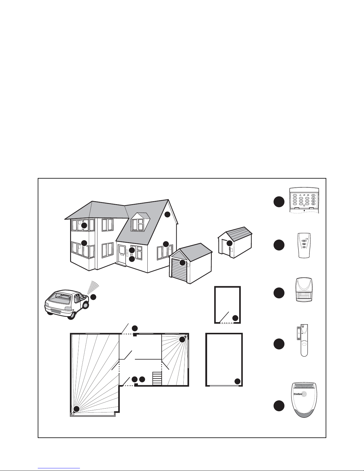
TYPICAL INSTALLATION
The following example below shows a typical
property incorporating the suggested positions for
the Siren, Keypad, PIR and Magnetic Contact
Detectors for optimum security. Use this as a
guide for your installation in conjunction with
the detailed positioning requirements for each
device provided in the appropriate installation
sections in this manual for planning your intruder
alarm system.
The alarm system may be extended to provide
greater protection and control by fitting additional
PlR Movement Detectors, Magnetic Contact
Detectors, Remote Controls and Keypads as
required. Any number of accessories may be
used with your system, provided that they are
all within radio range of the Siren.
PLANNING AND EXTENDING YOUR ALARM SYSTEM
Remote
Keypad
Magnetic
Contact
Detector
Remote
Control
PIR Movemen
t
Detector
SHED
LOUNGE
GROUND FLOOR
GARAGE
KITCHEN
HALL
DINING
ROOM
A
B
C
D
E
External
Solar Siren
Back Door
A
B
E
C
C
C
C
C
A
D
0
1 2 3
4 5 6
7 8 9
2
1
Friedland
™
D
D
D
D
D
D
REMOTE CONTROL UNIT
The Remote Control Unit(s) is used to Arm in either
Instant-Arm or Delay-Arm modes and to Disarm the
system.
The Remote Control Unit also incorporates a
Personal Attack (PA) switch. Activating the PA
switch on the side of the Remote Control will
immediately trigger an Alarm even if the system is
disarmed (unless the Siren is in Service Mode). The
alarm can be cancelled by pressing the ’DISARM’
button on the Remote Control.
Up to a total of 6 Remote Controls and/or Keypad Units
can be used with your system, providing they are all
operated within effective radio range of the Siren.
The Remote Control is powered by a CR2032 type
Lithium cell which under normal conditions will have an
expected life of approximately 1 year. Under normal
battery conditions the Transmit LED on the Remote
Control will only illuminate when a button is pressed.
However, under low-battery conditions this LED will
continue to flash after the button has been released.
When this occurs the battery should be replaced as
soon as possible.
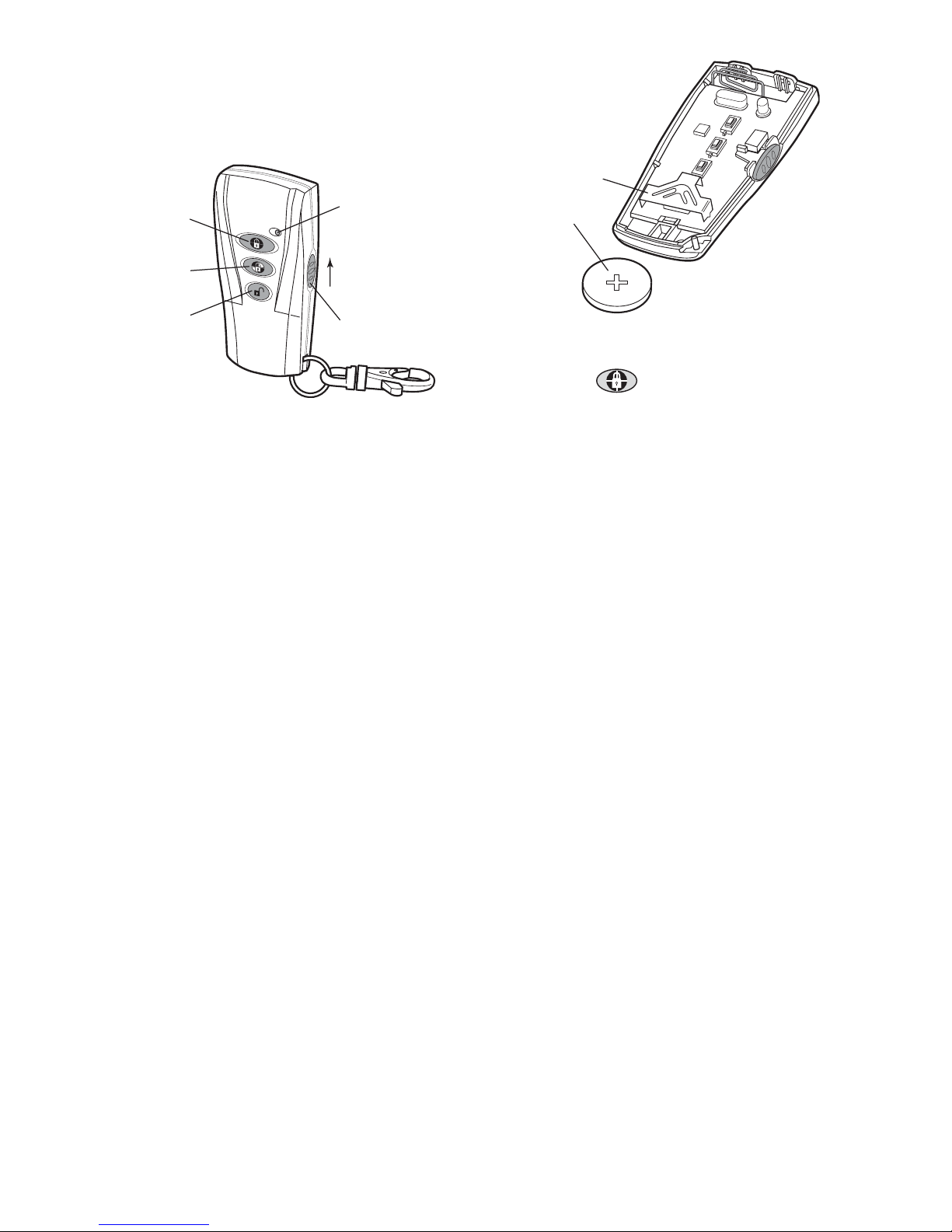
CONFIGURING THE REMOTE CONTROL
1. Remove the rear cover by undoing the small
screw on the rear of the Remote Control and
keeping it safe for later.
2. Insert the battery under the clip ensuring that
the +terminal faces upwards away from the
Circuit Board.
3. Replace the rear cover and fixing screw. Do not
over tighten the screw as this could damage the
thread.
TESTING THE REMOTE CONTROL
4. Press the button. The Transmit LED
should illuminate while the button is pressed and
extinguish within 1 second of releasing the button.
5. Pressing any button on the Remote Control will
illuminate the Transmit LED as before to check
that it is functioning correctly.
6. In order to communicate with the Siren, the ID
code of the Remote Control needs to be learned
by the Siren, subject to the Siren Unit being
installed and configured if it is being set-up for
the first time (see pages 10 - 12).
KEYPAD
The Keypad is used to control the Siren and to Arm
and Disarm the system by entering a 4 digit User
Access Code. The Keypad can arm the system in
either Instant or Delay modes.
The Keypad incorporates a tamper protection facility.
Any attempt to open the casing of the Keypad will
immediately trigger an alarm even if the system is
disarmed, (unless the system is in Service Mode).
In addition if a sequence of more than 16 incorrect
key presses is entered the Keypad will be disabled
for the next 1 minute, (except for the tamper
protection function). If the Keypad is disabled three
times consecutively a ‘Tamper signal’ will be triggered.
Up to a total of 6 Keypad Units and/or Remote Controls
can be used with your system, providing they are all
operated within effective radio range of the Siren.
The Keypad also incorporates a Personal Attack (PA)
facility which will immediately trigger an alarm when
activated, (unless the Siren is in Service Mode).
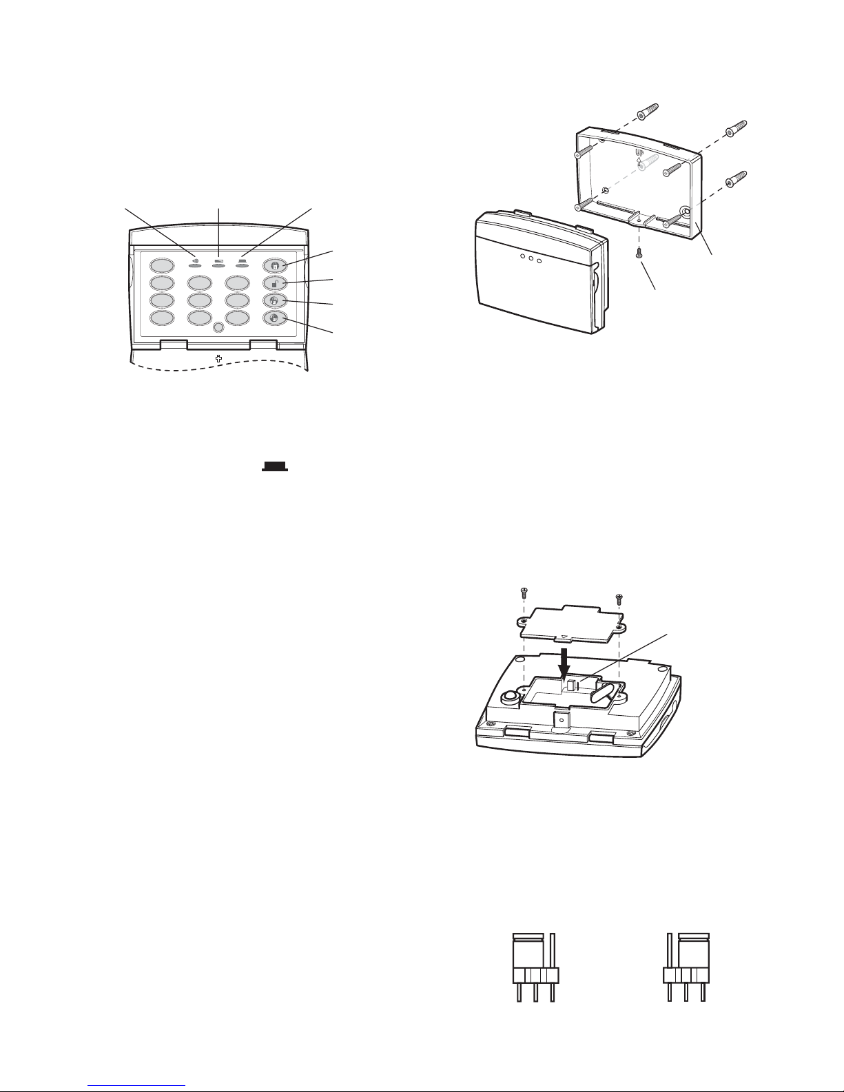
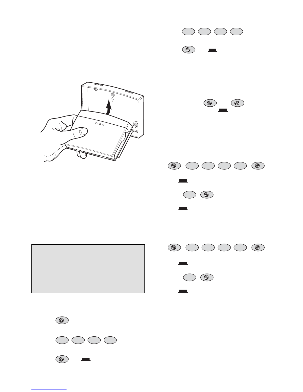
7
Slide up
to operate
Transmit LED
Personal Attack
Switch
Instant-Arm
Delay-Arm
Disarm
Battery Clip
Battery
8
The Keypad is powered by a PP3 Alkaline battery
which under normal conditions will have an expected
life of approximately 1 year. When the battery level
drops, the “LOW BATT” LED on the front of the
Keypad will flash. When this occurs the battery
should be replaced as soon as possible.
When using the Keypad the buttons must be pressed
firmly and within five seconds of each other. If you
make a mistake, wait ten seconds and start again.
When a button is pressed the LED will illuminate.
The Keypad has a back light which illuminates the
buttons for 5 seconds when the cover is first opened
or for 5 seconds after any key is pressed.
POSITIONING THE KEYPAD
The Keypad is suitable for mounting in dry interior
locations only.
The Keypad should be located within a protected
area so that it cannot be reached by an intruder
without opening a protected door or passing through
an area protected by a PIR Movement Detector.
The Keypad should be mounted in a position close to
the main entrance door so that the User Access
Code can be entered and the alarm system shut
down within the 15 seconds entry time period.
Note: DO NOT fix the Keypad onto or very close to
metalwork (e.g. radiators, water pipes, etc) as this
could affect the radio range of the device.
INSTALLING AND CONFIGURING
THE KEYPAD
Note: If adding a Keypad to an installed system,
ensure that the Siren is in Service Mode before
commencing installation, (see page 19). Remember
to switch the Siren back to Operating Mode after
installation is complete, (see page 19). If the Siren
Unit is being installed and configured for the first
time refer to pages 10 - 12.
1. Undo and remove the fixing screw from the
bottom edge of the Keypad and remove the wall
mounting plate.
2. Using the mounting plate as a template, mark
the positions of the four fixing holes on the wall.
A small spirit level will ensure it is perfectly level.
3. Fix the mounting plate to the wall using the four
18mm No.4 screws and 22mm wall plugs as
required, (a 5mm hole will be required for the
wall plugs). Do not over-tighten the screws as
this may distort or damage the mounting plate.
4. Undo and remove the two fixing screws securing
the rear battery cover and remove the cover.
5. If the battery has already been installed then
remove it.
6. Press and hold any key for more than 1 second.
7. Set the jumper link J1 as shown in Fig. 1b:
Wall Fixing
Plate
Fixing Screw
Low Battery
Indicator LED
Transmit
Indicator LED
Instant-Arm
0
1 2 3
4 5 6
7 8 9
2
1
Button Press
Indicator LED
Disarm
Delay-Arm 1
Delay-Arm 2
Jumper Link J1
3
31
1
Fi
g
. 1a Fig. 1b
8. Connect the PP3 alkaline battery to the battery
clip and set the jumper link J1 shown in Fig. 1a
which is what the keypad is set to normally.
9. Replace the rear cover and refit fixing screws.
Do not over-tighten the fixing screws.
10.
Refit and secure the Keypad onto the wall
mounting plate. Do not over-tighten the
fixing screw.
11. In order to communicate with the Siren, the ID
code of the Keypad needs to be learned by the
Siren after the Siren has been setup if the
installation is new (see page 12).
CHANGING THE USER ACCESS CODE
The Keypad is supplied with a User Access Code of:
“1234”. For security reasons, this code should be
changed to another 4 digit number which only you
and other users of the system should know.
To change the User Access Code, press the
following keys in sequence:
1. Press
2. Enter the factory set (or current) User Access
Code:
3. Press the LED will flash 3 times.
4. Enter a new User Access Code of your choice:
5. Press the LED will flash 4 times to
confirm the setting has been accepted. If the
LED does not flash, wait 10 seconds and try
steps 1 - 5 again.
PERSONAL ATTACK/ PA
Default setting:
ON
Press and hold both and together for
more than 2 seconds. The LED will flash
rapidly if both buttons are pressed at the same time.
The Personal Attack/PA feature can be disabled if
required as follows.
To Enable the Personal Attack/PA Feature:
1. Press
The LED will flash three times.
2.
Press
The LED will flash four times to confirm
the setting has been accepted.
To Disable the Personal Attack/PA Feature:
1. Press
The LED will flash three times.
2.
Press
The LED will flash four times to confirm
the setting has been accepted.
RESETTING TO FACTORY DEFAULTS
If unfortunately, you forget the Administrator/ User
Access Code, you can set it back to factory default
as follows:
1. Remove the battery.
2. Press and hold any key for more than 1 second.
9
New User Access Code
? ? ? ?
, ,
Current User Access Code
? ? ? ?
2
2
, ,
Current User Access Code
? ? ? ?
2
2
Factory Default User Access Code
1 2 3
4
1
1
1
1
2
1
,
2
0
,
2
IMPORTANT: When using the Keypad the keys
must be pressed firmly and within 5 seconds of
each other.
If you make a mistake, wait 10 seconds and
recommence programming from the beginning of
the sequence.
 Loading...