

FRIEDLAND SA1, SA2, SAC1 Installation & Operating Manual

Installation & Operating Manual
SA1, SA2(PF), SAC1
Wirefree
Alarm System
1
4
7
0
2
8
56
9
3
LOW BATT.
ON AIR
2
1

FOREWORD
All components in these wirefree Alarm Systems
are designed and manufactured to provide a high
standard of security protection and long, reliable
service. No radio operating licence is required for
this equipment.
These systems are designed for ease of installation
using only basic DIY tools. However, it is essential that
the installer reads and fully understands the advice
and procedures contained in this manual and plans
the system before proceeding with the installation.
During installation, it is important that the procedures
described in this manual are followed in sequence.
Note: This manual covers the installation and
operation of a number of different kit configurations.
Instructions relating to components not included in
your kit should be ignored.
This manual should be retained in a safe place for
future reference.
IMPORTANT
All components, with the exception of the External
Solar Siren are suitable for mounting in dry interior
locations only.
DECLARATION
Novar ED&S hereby declares that these SA1, SA2,
SA2PF and SAC1 wirefree alarm systems are in
compliance with the essential requirements and other
relevant provisions of the Radio and Telecommunications
Terminal Equipment (R&TTE) directive, 1999/5/EC.
Tools and Equipment Required:
No.0 Philips Screwdriver Drill
No.1 Philips Screwdriver Small Spirit Level
No.2 Philips Screwdriver Bradawl
5 & 6mm Masonry Drill Bits
DEVICE RANGE
The quoted range of the system devices (see
component specification on rear cover) is measured in
ideal conditions. Any solid object (e.g. walls, ceilings,
reinforced PVC doors etc) placed between the
transmitter devices and the Chime Unit will reduce the
transmission range of the devices.
The amount by which the range will be reduced is
dependant upon the nature of the barrier. e.g.
Wall Type Range Reduction
Dry-lined partition wall: 10-30%
Single layer brick wall: 20-40%
Double layer brick wall: 30-70%
Metal Panel/Radiator: 90-100%
Note: The effect on the range of multiple walls is
cumulative. i.e. if there are two brick walls in the way,
the range will be reduced by up to 40% by each wall.
SYSTEM SECURITY
This system has been designed to both detect
intruders and act as a strong deterrent to would-be
intruders when installed correctly.
Please remember that given adequate knowledge and
time it is possible to overcome any alarm system and
we therefore recommend that an Intruder Alarm is
used in conjunction with good physical protection
such as security window and door locks.
All units in the system are encoded to operate
together using an 8 bit House Code which is
configured by the user/installer to provide the
identification code for your installation. The system
House Code can be changed at any time by the user.
The system is operated from one or more Remote
Control units and/or Keypads. Care should be taken
to ensure that your Remote Control Unit(s) are not lost
or the Keypad User Access Code does not become
known to other people as this will compromise the
security of your system. In either event the system
house code and/or User Access Code should be
changed as soon as possible.
IMPORTANT: All units in your system must be set
to the same House Code which must be changed
from the factory supplied setting.
SAFETY
Always follow the manufacturers advice when using
power tools; steps, ladders etc. and wear suitable
protective equipment (e.g. safety goggles) when
drilling holes etc.
Before drilling holes in walls, check for hidden
electricity cables and water pipes, the use of a
cable/pipe locater maybe advisable if in doubt
When using ladders, ensure that they are positioned
on a firm stable surface at the correct angle and
suitably secured before use.
The use of ear defenders is advisable when working in
close proximity to the Siren due to the high sound
level produced by this device.
SA1, SA2(PF), SAC1 Wirefree Alarm SystemFriedland

CONTENTS
Page No.
KIT CONTENTS 2
INTRODUCTION AND OVERVIEW 3
System Arming 3
Entry/Exit Delay 3
Zone Lockout 3
Tamper Protection 3
Jamming Detection 3
Battery Monitoring 3
System House Code 3
PLANNING AND EXTENDING YOUR WIREFREE
SOLAR ALARM SYSTEM 4
EXTERNAL SOLAR SIREN 5
Positioning the Solar Siren 5
Installing and Configuring the Solar Siren 5
Power-up of the Solar Siren 7
REMOTE CONTROL UNIT 7
Configuring the Remote Control 7
Testing the Remote Control and Siren 8
KEYPAD 8
Positioning the Keypad 9
Installing and Configuring the Keypad 9
Changing the User Access Code 9
Testing the Keypad 10
PASSIVE INFRA RED (PIR) MOVEMENT
DETECTORS 10
Positioning the PIR Movement Detectors 11
Installing and Configuring the PIR Movement
Detectors 11
Testing the PIR Movement Detectors 12
MAGNETIC CONTACT DETECTORS 13
Positioning the Magnetic Contact Detectors 13
Installing and Configuring the Magnetic
Contact Detectors 13
Testing the Magnetic Contact Detectors 14
Page No.
TESTING THE SYSTEM 15
Initial Testing 15
Testing An Installed System 15
OPERATING INSTRUCTIONS 15
Arming the System in Instant-Arm Mode 16
Arming the System in Delay-Arm Mode 16
Disarming The System 16
Personal Attack (PA) Alarm 16
Siren Service Mode 17
Siren Operating Mode 17
Battery Monitoring 17
MAINTENANCE 18
ALARM RECORD 19
TROUBLE SHOOTING 19
EXTENDING YOUR ALARM SYSTEM 20
COMPONENT SPECIFICATION Back Cover
1SA1, SA2(PF), SAC1
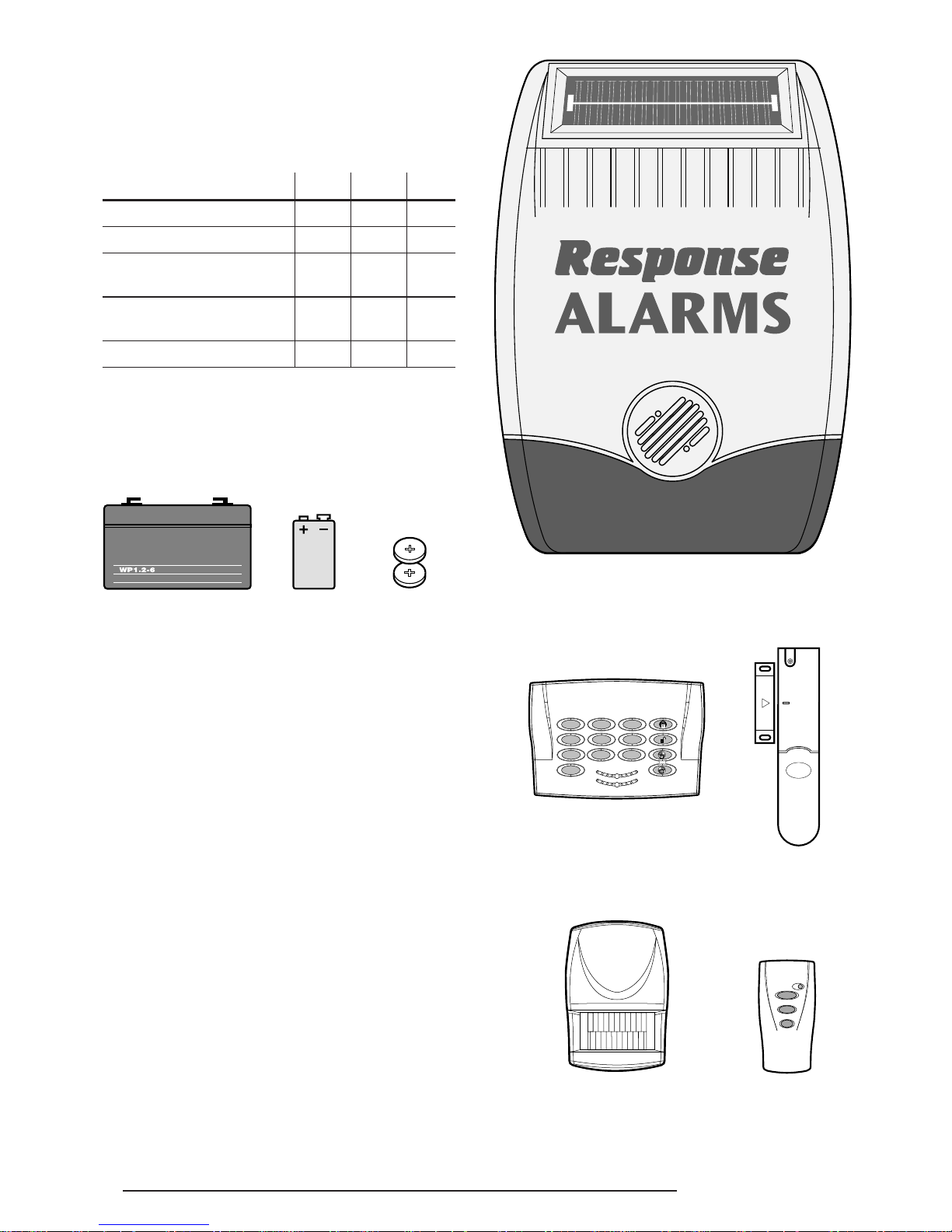
KIT CONTENTS
The Alarm System should contain the following
components.
Alarm System SA1 SA2
SA2PF
SAC1
External Solar Siren 1111
Remote Control 1111
PIR Movement
Detectors 2202
Magnetic Contact
Detectors 0232
Keypad 0111
Also included:
Installation & Operating Manual
Fixing pack
Batteries
EXTENDING THE ALARM SYSTEM
The following additional accessories are available to
enhance your system and provide further protection
and a higher level of security where required.
Component: Product Code
Two Magnetic Contact Detectors
and one Remote Control SU1
Two Passive Infra-Red
Movement Detectors SU2
Two Remote Controls SU3
Two Magnetic Contact Detectors SU4
Keypad SU5
External Solar Siren SU6
Full details of these accessories are given on page 21
and on the rear cover.
2 SA1, SA2(PF), SAC1
1
4
7
0
2
8
56
9
3
LOW BATT.
ON AIR
2
1
External Solar Siren
Keypad
Magnetic
Contact
Detector
Remote
Control
PIR Movement
Detector
6V/1.2Ahr Sealed lead
acid battery
(supplied fitted in Solar Siren)
9V PP3 Alkaline
battery
(for Keypad & PIR
Detectors)
3V CR2032
Lithium Coin Cell
(for Remote
Control and
Magnetic Contact
Detectors)
SYSTEM ARMING
The system has an ‘Instant-Arm’ and Delay-Arm’ mode.
If the system is armed in ‘Instant-Arm’ mode then all
detectors will immediately become fully armed. Any
detector triggered while the system is armed will
immediately initiate a full alarm condition.
ENTRY/EXIT DELAY
If the system is armed in ‘Delay-Arm’ mode this will
activate the system with a fixed 15 second entry/exit
delay period. This allows a 15 second period for the
user to exit the property after setting the system with
the Remote Control or at the Keypad. Any detector
triggered while the system is armed will not cause an
alarm condition until after the 15 second entry/exit
delay has expired. This allows time for the system to
be Disarmed before an alarm condition is triggered
when re-entering the property.
Note: To conserve power and maximise battery life
the PIR Detector will only detect movement if there
has been no movement detected within the previous
2 minutes. Consequently the PIR Detector will not
become active until the protected area has been free
from movement for more than 2 minutes.
ZONE LOCKOUT
If a detector is triggered while the system is armed an alarm
condition will occur. After the set alarm duration has expired
the alarm will stop and the system will automatically reset.
Subsequent detectors triggered will again initiate an alarm
condition. However, after an alarm condition has been
initiated three times the system will be ‘Locked Out’ and will
not reset, any further alarm signals from detectors will be
ignored until the system is disarmed.
TAMPER PROTECTION
All system devices (except any Remote Control Units)
incorporate Tamper protection features to protect
against unauthorised attempts to interfere with the
device. Any attempt to remove the battery cover from
any device (except a Remote Control) or to remove the
Solar Siren from the wall will initiate an alarm condition
(unless the system is in Service Mode), even if the
system is Disarmed.
JAMMING DETECTION
In order to detect any attempts to illegally jam the radio
channel used by your alarm system, a special jamming
detection function is incorporated into the Solar Siren.
If this feature is enabled, and the radio channel is
jammed continuously for 30 seconds, when the system
is armed, the Solar Siren will emit a pre-alarm series of
rapid bleeps for 5 seconds. If the jamming continues
for a further 10 seconds or more a full alarm condition
will occur. In addition if the system is jammed for more
than three periods of 10 seconds in a 5 minute interval,
this will also generate a Full Alarm condition.
The Jamming Detection circuit is designed to
permanently scan for jamming signals. However, it is
possible that it may detect other local radio interference
operating legally or illegally on the same frequency. If it
is planned to operate the jamming detection feature we
recommend that the system is monitored for false
jamming alarms for at least 2 weeks prior to leaving the
Jamming Detection function permanently enabled.
BATTERY MONITORING
All devices powered by non-rechargeable batteries
incorporate a battery level monitoring feature which
will warn of a low battery status. The batteries on any
device indicating a low battery status should be
replaced immediately.
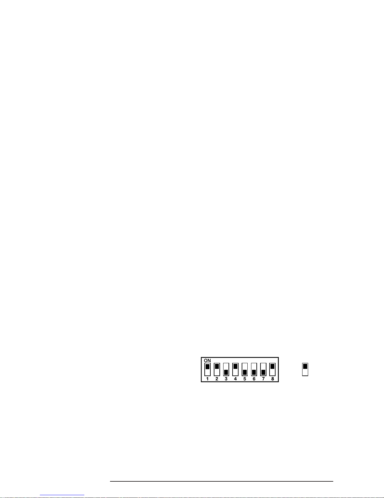
SYSTEM HOUSE CODE
In order to prevent any unauthorised attempt to
operate or disarm your system, you must configure
your system to accept radio signals only from your own
system devices. This is done by setting a series of
eight miniature (DIP) switches in all devices to the same
ON/OFF combination (the House Code) selected by
the user/installer. All detectors and Remote Control
Unit(s) must be configured with the same House Code
in order for the system to operate correctly.
Inside the detectors and Remote Control Unit is a
series of 8 DIP switches.
The House Code is set up by moving each of the 8
switches in each device to the same randomly
selected ON/OFF sequence. When setting the DIP
switches, ensure that each switch ‘clicks’ fully into
position. Use the tip of a ballpoint pen or a small
screwdriver to move each switch in turn.
Note: It is recommended that the system House
Code is always changed to a code other than
the factory.
INTRODUCTION AND OVERVIEW
SA1, SA2(PF), SAC1 3
e.g.
Switch 1
set to the
ON position
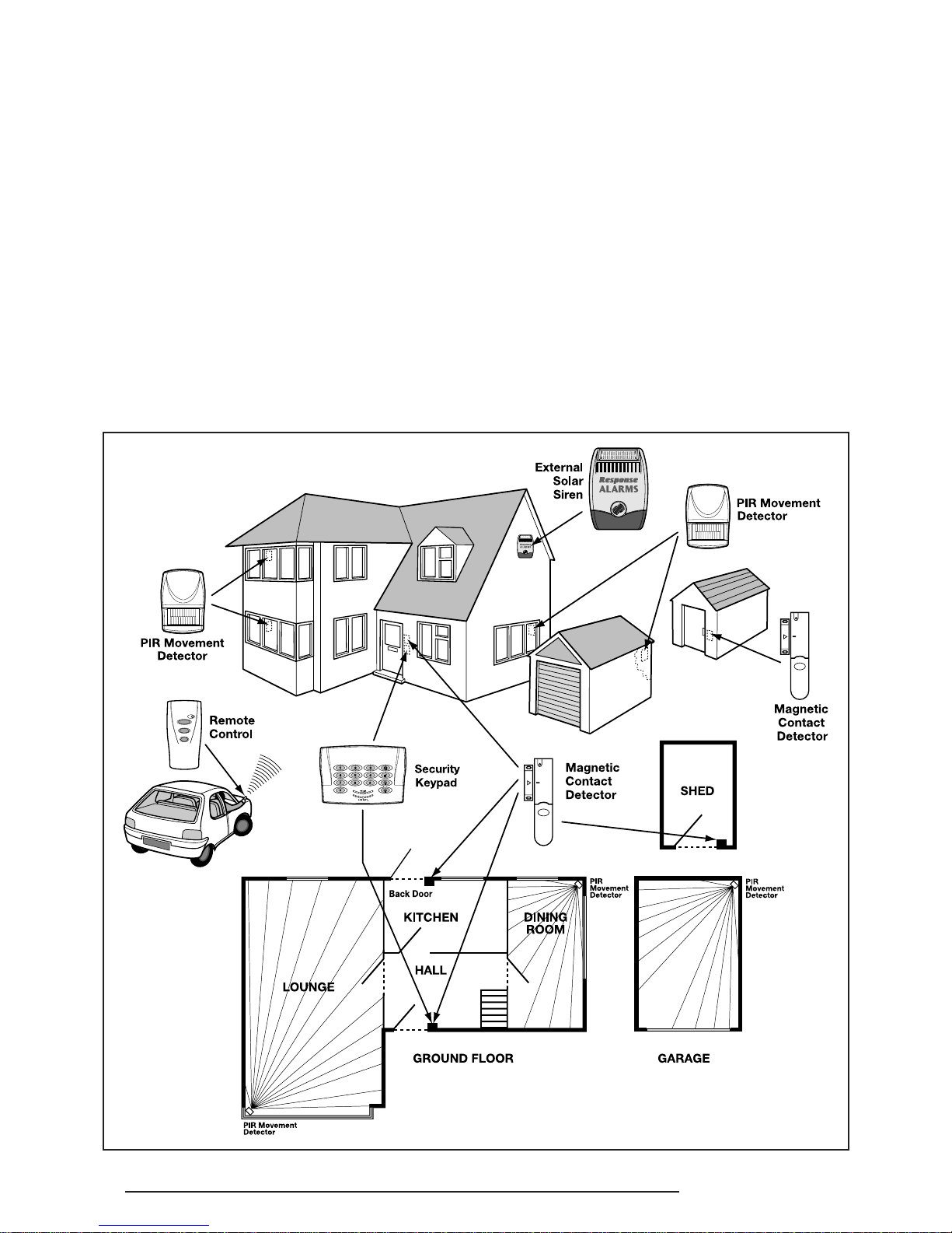
PLANNING AND EXTENDING YOUR WIREFREE
ALARM SYSTEM
SA1, SA2(PF), SAC14
Before attempting to install your Alarm System it is
important to study your security requirements and plan
your installation.
PIR Movement Detectors are used to protect the main
areas of the property, (e.g. lounge, study, hallway and
landing). Magnetic Contact Detectors are typically used
to protect the main access points to the property,
(e.g. front door, back door, patio doors). However, they
can also be used to protect other vulnerable doors/
windows or access doors to important rooms.
The following example below shows typical property
incorporating the suggested positions for the External
Siren, Keypad, PIR and Magnetic Detectors for
optimum security. Use this as a guide for your
installation in conjunction with the detailed positioning
requirements for each device provided in the
appropriate installation sections in this manual for
planning your intruder alarm system.
The alarm system may be extended to provide greater
protection and control by fitting additional PlR
Movement Detectors, Magnetic Contact Detectors,
Remote Controls and Keypads as required. Any number
of accessories may be used with your system, provided
that they are all coded with the system House Code.
EXTERNAL SOLAR SIREN
The Siren and Solar Panel are all encapsulated within
a tough polycarbonate housing. This housing provides
full protection against adverse weather conditions.
An LED indicator is built into the siren to act as a
visible deterrent/indication that the system is active.
The indicator LEDs will slowly and alternately flash
whether the system is Armed or Disarmed. During an
alarm condition the indicator LEDs will flash rapidly.
An integral anti-tamper switch provides additional
security protection to the Siren and will immediately
generate a full alarm should any unauthorised attempt
be made to interfere with and remove the siren cover.
The Siren is powered by a high capacity 6V/1.2Ahr
rechargeable sealed lead acid battery. A Solar Panel
mounted on the top of the housing charges the battery
during daylight hours. During darkness, only a small
amount of energy is required to operate the Siren unit.
A 9V Alkaline PP3 battery is supplied in the External
Siren to boost the initial power to the unit when the
system is first activated until the Solar Panel charges
the main battery. (This battery is only designed to last
for a short period until the main rechargeable battery
has obtained sufficient charge).
The Siren unit incorporates the installations Jamming
Detection system which will (if activated) generate an
alarm if any attempt is made to continuously jam the
radio channel used for the system.
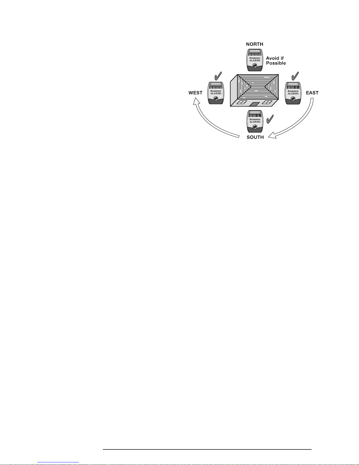
POSITIONING THE SOLAR SIREN
The Siren should be located as high as possible in a
prominent position so that it can be easily seen and
heard. The Siren should be mounted on a sound flat
surface so that the rear tamper switch is not activated
when mounted. Ensure that the tamper switch does
not fall into the recess between brick courses as this
could prevent the switch from closing and give a
permanent tamper signal.
In order to provide the maximum amount of daylight
to the Solar Panel, the siren should ideally be mounted
on a south facing wall. However, an easterly or
westerly position will suffice.
Mounting the device on a north facing wall should be
avoided as this could mean that during the short dark
days of winter months the solar panel may not receive
sufficient daylight in order to maintain the battery
charge at acceptable levels.
Shadows cast by neighbouring walls, trees and roof
overhangs should also be avoided. If the Siren is to be
mounted below the eaves, it should be positioned a
distance of at least twice the width of the eaves
overhang below the eaves. Remember that in winter
the sun is lower in the sky and you should avoid winter
shadows where possible.
The External Solar Siren contains a sophisticated
radio receiver. However, reception of radio signals can
be affected by the presence of metallic objects within
the vicinity of the Receiver. It is therefore important to
mount the Solar Siren a minimum distance of 1m away
from any external or internal metalwork, (i.e.
drainpipes, gutters, radiators, mirrors etc.).
It is recommended that you check the suitability of
your chosen location for the Solar Siren by temporarily
fitting it to the external wall. Using the Remote
Control, (as described below) power up the Siren and
check that you can operate the Siren from in and
around the property, and from all locations where you
plan to install detectors.
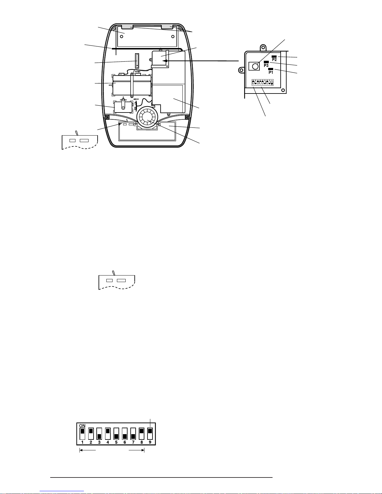
INSTALLING AND CONFIGURING
THE SOLAR SIREN
1. Remove the fixing screw from the bottom edge of
the Siren housing and carefully hinge off the front
cover. All electronic components are housed
within the front cover.
2. Hold the mounting plate in position and mark the
positions of the four mounting holes. A spirit level
placed on the casing will ensure a perfect level.
3. Fit two 30mm fixing screws in the top holes leaving
approximately 10mm of the screw protruding.
SA1, SA2(PF), SAC1 5
4. Fit the top keyhole slots of the mounting plate over
the screw heads. Remove the mounting plate and
adjust the screws until they form a neat fit with the
mounting plate with minimal movement.
5. Secure the mounting plate in position using two
25mm fixing screws in the bottom fixing holes.
6. Ensure that the Solar Siren main configuration
switch on the LED indicator board is set to "C.U."
for use with this alarm system.
7. Undo the 3 screws holding the DIP Switch Cover
in place and remove the cover.
8. Under the cover you will find a series of 9 DIP
switches.
Note: When the Solar Siren is viewed as shown
above (Solar panel at top) the DIP switches are
‘upside down’.
9.
Select and record a random combination of ‘ON’ and
‘OFF’ positions for DIP switches 1- 8. This will be the
system House Code that will enable all devices on
the system to communicate with the Solar Siren.
IMPORTANT: The house code for your system
should be changed from the factory default settings.
10.
Set the alarm duration time using DIP switch 9 as
follows:
ON = 3 minutes
OFF = 1 minute
11. The Solar Siren will acknowledge signals from
the Remote Control and Keypad by beeping. It is
possible to disable these acknowledgement beeps
if required by removing the jumper link P2 on the
circuit board.
P2 fitted =
beep enabled
P2
removed = beep disabled
12.
If for any reason you need to disable the Siren,
remove jumper link P3 on the circuit board. This
will prevent the Siren from sounding during an
alarm condition. However, the Siren will still beep
to acknowledge signals from the Remote Control,
(provided the beep feature is not disabled).
P
3 fitted = Siren enabled
P
3 removed = Siren disabled
13.
To enable the Jamming Detect feature in the Solar
Siren fit the jumper link taped to the cover of the Siren
control unit across link pins P1 on the circuit board.
P1 fitted = Jamming Detection enabled
P1 removed = Jamming Detection disabled
14.
Refit the DIP switch cover and replace the three
cover fixing screws. Do not over tighten the screw
as this could damage the thread.
Tamper
switch
6 Volt 1.2Ahr
rechargeable
battery
9 Volt PP3 initial
power up battery
Siren
Printed circuit
board enclosure
Receiver
Aerial
DIP switch
cover
Alarm duration
DIP switch 9
House Code
DIP switches 1-8
7.5 Volt DC
charging adaptor
input
Front cover
locating tabs
Bleep Disable Link
Siren Disable Link
Jamming
Detection Link
LED Indicator PCB
Solar Panel
C.U.
Main Configuration
Switch (in C.U. Position)
SIREN
C.U. SIREN
Alarm Duration DIP Switch 9
House Code
(Always change from the factory setting)
View of inside
Solar Siren
6 SA1, SA2(PF), SAC1
Main Configuration
Switch (in C.U. Position)
C.U. SIREN
 Loading...