

FRIEDLAND SA5 Installation And Operating Manual
Installation & Operating Manual
SA5
6 Zone Communicating
Wirefree Alarm System

FOREWORD
All components in this wirefree Alarm System are
designed and manufactured to provide a high standard
of security protection and long, reliable service.
The system is designed for ease of installation using only
conventional domestic tools. However, it is essential
that the installer reads and fully understands the advice
and procedures contained in this manual and plans the
system before proceeding with the installation.
During installation, it is important that the procedures
described in this manual are followed in sequence.
This manual should be retained in a safe place for
future reference.
IMPORTANT
All components are suitable for mounting in dry interior
locations only.
DECLARATION
Friedland hereby declares that this wirefree alarm
system is in compliance with the essential
requirements and other relevant provisions of the
Radio and Telecommunications Terminal Equipment
(R&TTE) directive, 1999/5/EC.
Tools and Equipment Required:
No.0 Philips Screwdriver Drill
No.1 Philips Screwdriver Small Spirit Level
No.2 Philips Screwdriver Bradawl
5 & 6mm Masonry Drill Bits
IMPORTANT
Local Authority Regulations And Legislation'.
This alarm system should be installed and operated in
accordance with the requirements of any current local
and/or national regulations and legislation. We
recommend that you contact your authority to obtain
details of any your area's requirements local and/or
national regulations.
For example in Belgium, the installation and use of an
alarm system including notification by telephone (Voice
Dialler) functionality and the optional use of an external
siren is controlled by Belgium legislation "KB" of
19/06/2002.
DEVICE RANGE
The quoted range of the system devices (see
component specification on rear cover) is measured in
ideal conditions. Any solid object (e.g. walls, ceilings,
reinforced PVC doors etc) placed between the
transmitter and Receiver Devices and the Chime Unit
will reduce the transmission range of the devices.
The amount by which the range will be reduced is
dependant upon the nature of the barrier. e.g.
Wall Type Range Reduction
Dry-lined partition wall: 10-30%
Single layer brick wall: 20-40%
Double layer brick wall: 30-70%
Metal Panel/Radiator: 90-100%
Note: The effect on the range of multiple walls is
cumulative. i.e. if there are two brick walls in the way,
the range will be reduced by up to 40% by each wall.
SYSTEM SECURITY
This system has been designed to both detect
intruders and act as a strong deterrent to would-be
intruders when installed correctly.
Please remember that given adequate knowledge and
time it is possible to overcome any alarm system and
we therefore recommend that an Intruder Alarm is used
in conjunction with good physical protection such as
security window and door locks.
All units in the system are encoded to operate together
using an 8 bit House Code which is configured by the
user/installer to provide the identification code for your
installation. The system House Code can be changed
at any time by the user.
The system is operated from one or more Remote
Control units and/or the Control Panel. Care should be
taken to ensure that your Remote Control Unit(s) are
not lost or the User Access Codes for the Control
Panel do not become known to other people as this
will compromise the security of your system. In either
event the system house code and User Access Codes
should be changed as soon as possible.
SAFETY
Always follow the manufacturers advice when using
power tools; steps, ladders etc. and wear suitable
protective equipment (e.g. safety goggles) when
drilling holes etc.
Before drilling holes in walls, check for hidden
electricity cables and water pipes, the use of a
cable/pipe locater maybe advisable if in doubt.
When using ladders, ensure that they are positioned on
a firm stable surface at the correct angle and suitably
secured before use.
The use of ear defenders is advisable when working in
close proximity to the Siren due to the high sound level
produced by this device.
SA5 6 Zone Communicating Wirefree Alarm SystemFriedland
IMPORTANT: All units in your system must be set
to the same House Code which must be changed
from the factory supplied setting.

CONTENTS
Page No.
KIT CONTENTS 2
INTRODUCTION AND OVERVIEW 3
Multiple Users 3
System Arming 3
Entry/Exit Delay 3
Zones 3
Zone Lockout 3
Quick Set 4
Final Exit Set Zone 4
Walk Through Zone 4
Omit Zone 4
Event Log 4
Chime 4
Voice Dialler 4
Remote Manager 4
Latch-Key 4
Answer-Phone 5
Voice Memo 5
Remote Phone Access and Control 5
Tamper Protection 5
Jamming Detection 5
Battery Monitoring 5
System House Code 5
PLANNING YOUR ALARM SYSTEM 6
REMOTE CONTROL UNIT 7
General Information 7
Configuring the Remote Control 7
CONTROL PANEL 8
Positioning the Control Panel 8
Installing the Control Panel 8
Configuring the Control Panel House Code 10
Testing the Control Panel & Remote Control 10
PASSIVE INFRA RED (PIR)
MOVEMENT DETECTORS 11
Positioning the PIR Movement Detectors 11
Installing and Configuring the PIR
Movement Detectors 12
Testing the PIR Movement Detectors 13
MAGNETIC CONTACT DETECTORS 14
Positioning the Magnetic Contact Detectors 14
Installing and Configuring the
Magnetic Contact Detector 14
Testing the Magnetic Contact Detector 15
EXTERNAL CONNECTIONS 16
Page No.
TESTING THE SYSTEM 17
Initial Testing 17
Testing an Installed System 17
DEFAULT SETTINGS 19
Reset Factory Default Conditions 19
PROGRAMMING 20
Navigating through the Programming
Mode Menus 20
Telephone Application Setup 21
Voice Dialler 21
Remote Manager 21
Answer-Phone 21
Latch Key 21
User Setup 21
System Setup 22
Zone Setup 25
Voice Dialler Setup 27
Full Arm Setup 29
Part-Arm 1 Setup 30
Part-Arm 2 Setup 31
Time & Date Setup 32
Latch Key Setup 32
Answer Phone Setup 33
Remote Manager Setup 34
OPERATING INSTRUCTIONS 35
Arming the System 35
Part-Arming the System: Part-Arm 1 35
Part-Arming the System: Part-Arm 2 35
Disarming the System 36
Quick Set 36
Omit Zone 36
Personal Attack (PA) Alarm 36
Tamper 36
Chime 36
Event-Log 37
Leaving a Voice Memo Message 37
Replaying and Deleting Messages
at the Control Panel 37
Remote Phone Access and Control 37
Solar Siren Service and Operating Modes 38
Battery Monitoring 39
MAINTENANCE 40
ALARM RECORD 41
TROUBLE SHOOTING 42
EXTENDING YOUR ALARM SYSTEM 45
COMPONENT SPECIFICATION Back Cover
1SA5
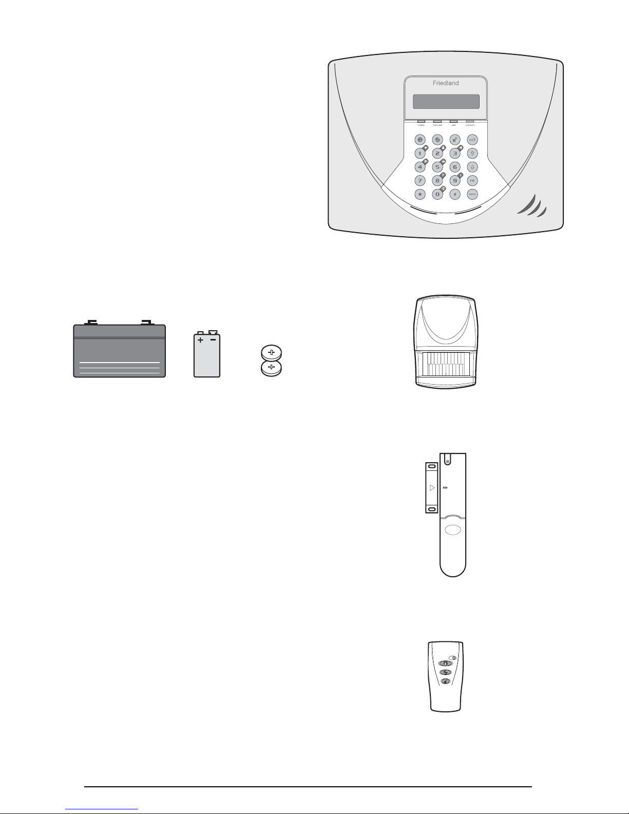
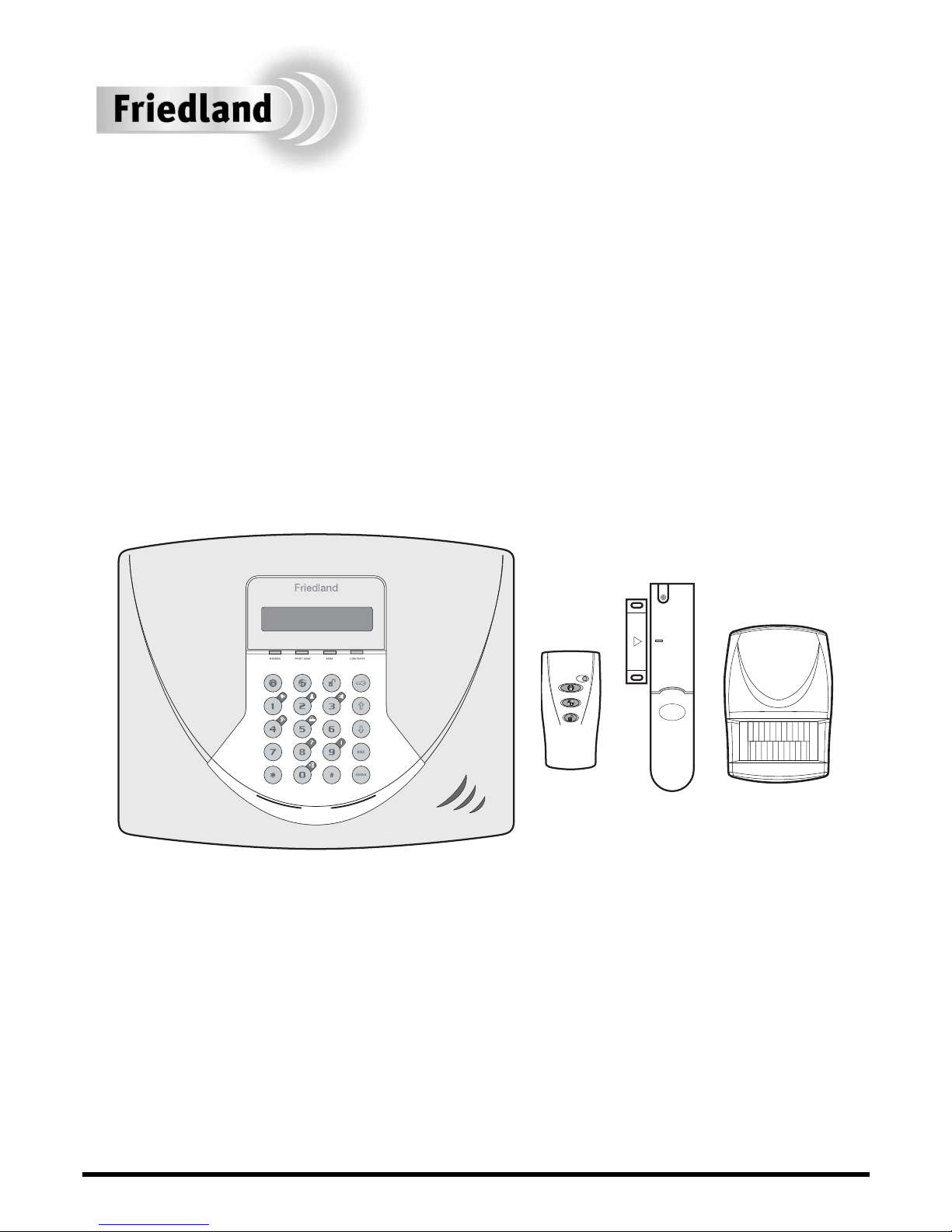
KIT CONTENTS
The Alarm System should contain the following
components.
1xControl Panel
1xRemote Control
1xPIR Movement Detector
1xMagnetic Contact Detector
Also included:
Telephone Connection Lead
Power Supply Adaptor
Installation & Operating Manual
Fixing pack
Batteries
2 SA5
WP1.2-6
Control Panel
6V/1.2Ahr
Sealed lead acid battery
(supplied fitted in
Control Panel)
9V PP3
Alkaline battery
(for PIR Detector)
3V CR2032 Lithium
Coin Cell (for
Remote Control
and Magnetic
Contact Detector)
Magnetic Contact
Detector
Remote Control
PIR Movement
Detector
MULTIPLE USERS
The system allows for up to 6 Users and a Master User
to be configured. This allows the system Event Log to
maintain a record of which users have armed and
disarmed the system. Each user will have a different
Access Code. In addition a 4 second voice recorder
facility enables the users name to be recorded for use
with the Latch-Key facility.
Only the Master User has access to the programming
functions and is able to configure the system.
Note: Any Remote Control Units on the system will be
recorded as User 6.
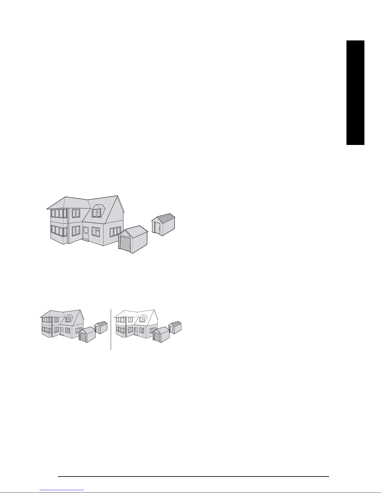
SYSTEM ARMING
The system has a full ‘Arm’ and a ‘Part-Arm’ mode.
Full ARM will arm all zones while the ‘Part-Arm’ mode
will only arm the zones that are enabled for “Part-Arm”.
For example:
The system could be configured such that during night
time, ‘Part-Arm 1’ would arm only zones protecting the
lower floor and outbuildings leaving the upper floor free
for movement without triggering the alarm.
During the day while the property is occupied ‘Part-Arm
2’ would arm only the zones protecting the outbuildings.
However, when the property is left un-occupied, the full
‘Arm’ mode will arm all zones to protect the entire
property, (i.e. upper and lower floors and outbuildings).
ENTRY/EXIT DELAY
When the system is armed with the Exit-Delay enabled,
no alarm signal from any detector on an active zone
will be able to initiate an alarm until the Exit-Delay has
expired. This enables the system to be armed from
within the property and allows time for the user to exit
the property without triggering an alarm. If the Exit-
Delay is disabled then detectors on active zones will
immediately be able to initiate an alarm as soon as the
system begins to arm.
The system Exit-Delay may be configured for between
10 to 250 seconds or disabled completely.
If a detector on a zone with its Entry-Delay enabled is
triggered, then an alarm condition will not occur until
the Entry-Delay period has expired. This allows time
for the user to re-enter the property and disarm the
system before an alarm condition occurs. Generally
only the zones on the main entry route to the property
will be configured with an Entry-Delay. The remaining
zones would be configured with their Entry-Delay
disabled allowing them to immediately initiate an alarm
the instant a detector on the zone is triggered.
The Entry-Delay for each zone may be configured for
between 10 to 250 seconds or disabled completely.
Note: To conserve power and maximise battery life
the PIR Detector will only detect movement if there
has been no movement detected within the previous
2 minutes. Consequently the PIR Detector will not
become active until the protected area has been free
from movement for more than 2 minutes.
ZONES
The system incorporates 6 wirefree Alarm Zones for
the connection of the system detectors that are used
to independently monitor different areas of the
property. In addition to standard intruder protection,
each zone may also be configured to operate in one of
four other modes:
– ‘Personal Attack’ mode provides 24 hour monitoring
of any Personal Attack (PA) switches incorporated
into the system.
– ‘24-hour Intruder’ mode provides 24 hour intruder
protection for areas where continuous monitoring is
required, (e.g. gun cupboards).
– ‘Fire’ mode provides 24 hour monitoring of any
Fire/Smoke detectors incorporated into the system.
In addition there is the facility to connect 4 hard wired
zones to the Control Panel, each of which is fully
configurable with the same features as the wirefree zones.
ZONE LOCKOUT
If a detector on an active zone is triggered while the
system is armed an alarm condition will occur. After
the programmed alarm duration has expired the alarm
Full Arm
Full Arm Part-Arm
INTRODUCTION AND OVERVIEW
SA5 3
INTRODUCTION

will stop and the system will automatically reset.
Subsequent detectors triggered will again initiate an
alarm condition. If a single zone initiates an alarm
condition more than three times then that zone will be
‘Locked Out’ and any further alarm signals from that
zone will be ignored until the system is disarmed.
Note: The ‘Zone Lockout’ feature can be disabled if
required.
QUICK SET
The system may be fully armed in 5 seconds using the
quick set facility, overriding the programmed exitdelay. This is useful for setting the system at night
when the exit-delay warning beep will be silenced after
just a few seconds.
FINAL EXIT SET ZONE
Triggering a detector on a Final Exit zone during the
exit-delay will cause the delay to reset to 5 seconds
with the system arming 5 seconds later.
WALK THROUGH ZONE
This feature may be used to temporarily disable
detectors on zones covering the route between the
main entry door and the Control Panel.
If the system is armed and the property is accessed via
the “Entry-Door” zone then the setup entry-delay will
operate as normal. However all “Entry-Route “ zones
will be disabled to allow free access to the Control
Panel to Disarm the system before the entry-delay on
the “Entry-Door” zone expires an alarm occurs.
If access is gained via any zone that is not configured
as the “Entry-Door” then all zones (including those
setup as the “Entry-Route” will operate as normal
according to their normal configuration.
Note: The zone configured as the “Entry Door” must be
setup with an Entry-Delay sufficient to reach the Control
Panel and Disarm the system. Zones configured as the
“Entry Route” should be setup without an Entry-Delay.
OMIT ZONE
A zone may be temporarily omitted when the system is
armed using the Omit feature. When the system is
next disarmed any zones set to Omit will be cancelled.
EVENT LOG
The Control Panel incorporates a memory capable of
storing the last 50 system events. This enables the
user to see which user has Armed/Disarmed the
system and if and when any alarms occurred. The
time, date and details of the event type will be
recorded for each system event.
CHIME
Chime is a low security facility for use when the system
is Standby mode. If the Chime feature is ON, and a
detector on a zone that has its Chime function enabled
is triggered, the internal sounder will produce a low
volume warning tone. A typical use of the Chime
function would be to warn that a door or particular area
has been accessed.
VOICE DIALLER
This system incorporates a telephone voice dialler that
is used to call for help and/or notify the user that the
system has been triggered and an alarm has occurred.
If the Voice Dialler is enabled and an alarm condition
occurs, the system will call for help using your recorded
alarm message and up to four telephone numbers. When
the telephone voice dialler is activated it will call the first
enabled number in the dialling sequence and replay the
recorded alarm messages for the configured ‘Play Time’.
The recipient must acknowledge the message by
pressing the button on their telephone keypad. If
the call is unanswered or an acknowledgment signal is
not received then the next active number in the dialling
sequence will be called. The dialler will continue calling
each number in turn until either all numbers in the
sequence have been dialled the set number of times or
the dialling sequence is cancelled by an acknowledged
signal from the recipient.
REMOTE MANAGER
As an alternative to the Voice Dialler the system may
be configured to interface direct with an Alarm
Monitoring Service using the Ademco Contact ID
communications protocol.
This is an independent service not provided by Novar
Friedland.
Note: Remote Manager may not be supported in all
countries. Please refer to enclosed literature, or
contact your local help line for availability.
LATCH KEY
When the system is disarmed the Latch-Key facility,
if enabled, will call the first latchkey phone number
and replay the user message (recorded under user
setup) for the set ‘Play Time’. The recipient must
acknowledge the message by pressing the button
on their telephone keypad. If the call is unanswered or
an acknowledgment is not received then the second
latchkey phone number will be called. The voice dialler
will continue calling each number in turn until each
number has been dialled the set number of times or the
sequence is cancelled/acknowledged by the recipient.
SA54
INTRODUCTION

SA5 5
INTRODUCTION
For example, the latchkey facility is useful to inform
parents that a child has returned from school and
disarmed the system.
ANSWER PHONE
The Control Panel includes an answer-phone facility.
The answer phone will record and store a maximum
of 6 messages with each message being limited to a
30s duration.
Messages may be retrieved either direct from the
Control Panel or by dialling into the system from a
phone.
VOICE MEMO
In addition it is also possible to record messages at
the Control Panel using the ‘Voice-Memo’ facility. Each
voice-memo message is limited to a maximum duration
of 30s and counts as an answer phone message.
REMOTE PHONE ACCESS
AND CONTROL
It is possible to dial into the system via the connected
telephone line to interrogate the system status and to
have basic control over the system, (e.g. to Arm and
Disarm the system). You may also activate the
microphone on the control panel to Listen-In to what is
happening in the protected property.
Answer phone and Voice-memo messages may also
be accessed remotely.
TAMPER PROTECTION
All system devices (except any Remote Control Units)
incorporate Tamper protection features to protect
against unauthorised attempts to interfere with the
device.
Any attempt to remove the battery cover from any
device (except a Remote Control) or to remove the
Control Panel from the wall will initiate an alarm
condition (unless the system is in Test or Programming
modes), even if the system is Disarmed.
JAMMING DETECTION
In order to detect any attempts to illegally jam the radio
channel used by your alarm system, a special jamming
detection function is incorporated into the Control
Panel and optional Solar Siren. If this feature is
enabled, and the radio channel is jammed continuously
for 30 seconds, when the system is armed, the Solar
Siren will emit a pre-alarm series of rapid beeps for
5 seconds. If the jamming continues for a further
10 seconds or more a full alarm condition will occur. In
addition if the system is jammed for more than three
periods of 10 seconds in a 5 minute interval, this will
also generate a Full Alarm condition.
The Jamming Detection circuit is designed to
permanently scan for jamming signals. However, it is
possible that it may detect other local radio
interference operating legally or illegally on the same
frequency. If it is planned to operate the jamming
detection feature we recommend that the system is
monitored for false jamming alarms for at least 2 weeks
prior to leaving the Jamming Detection function
permanently enabled.
Note: The jamming detection features incorporated
into the Control Panel and optional Solar Siren operate
independently.
BATTERY MONITORING
All devices powered by non-rechargeable batteries
incorporate a battery level monitoring feature which will
warn of a low battery status. In addition the Control
Panel will also indicate a low battery status within any
Passive Infra-Red or Magnetic Contact Detector on the
system. The batteries on any device indicating a low
battery status should be replaced immediately.
SYSTEM HOUSE CODE
In order to prevent any unauthorised attempt to
operate or disarm your system, you must configure
your system to accept radio signals only from your own
system devices. This is done by setting a series of
eight miniature (DIP) switches in all devices (except the
Control Panel) to the same ON/OFF combination (the
House Code) selected by the user/installer. The
Control Panel is then programmed to operate only with
devices set to this House Code. All detectors and
Remote Control Unit(s) must be configured with the
same House Code in order for the system to operate
correctly.
Note: It is recommended that the system House
Code is always changed to a code other than the
factory setting.
SA56
INSTALLATION
Before attempting to install your Alarm System it is
important to study your security requirements and plan
your installation.
PIR Movement Detectors are used to protect the main
areas of the property, (e.g. lounge, study, hallway and
landing). Magnetic Contact Detectors are typically used
to protect the main access points to the property, (e.g.
front door, back door, patio doors). However, they can
also be used to protect other vulnerable doors/windows
or access doors to important rooms.
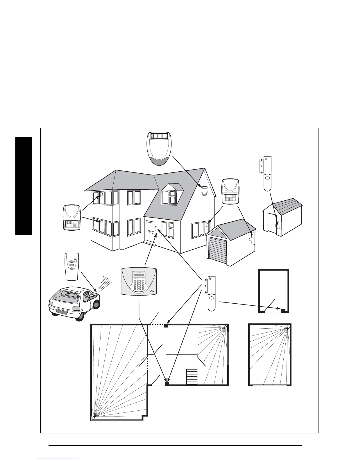
TYPICAL INSTALLATION
The following example below shows typical property
incorporating the suggested positions for the Control
Panel, PIR and Magnetic Contact Detectors and
optional Solar Siren. Use this as a guide for your
installation in conjunction with the detailed positioning
requirements for each device provided in the
appropriate installation sections in this manual for
planning your intruder alarm system.
PLANNING YOUR ALARM SYSTEM
LCD
Control
Panel
Magnetic
Contact
Detector
Magnetic Contact
Detector
External Solar
Siren
(Optional)
PIR Movement
Detector
PIR Movement
Detector
Remote
Control
SHED
LOUNGE
GROUND FLOOR
GARAGE
KITCHEN
HALL
DINNING
ROOM
PIR Movement
Detector
PIR
Movement
Detector
PIR
Movemen
t
Detector
Back Door
SA5 7
INSTALLATION
The system default settings are pre-configured to
provide a basic functional system to suit most typical
basic installations:
●
Zone 1 is configured as a Delay zone with a 30s
entry/exit delay
.
Any detectors covering the main door and the route
to the Control Panel should be set on zone 1 only.
●
Zones 2-6 are configured as INSTANT without any
entry/exit delay.
●
The system has a 3 minute alarm duration.
●
Zone Lockout is enabled.
●
PART-ARM 1 is configured to operate with detectors
on zones 1 to 4 only. Detectors on zones 5 & 6 are
inactive in Part-Arm 1.
●
PART-ARM 2 is OFF
●
All other system features, (e.g. telephone dialler,
answer phone, Latch-Key, Chime etc) are OFF or
not programmed.
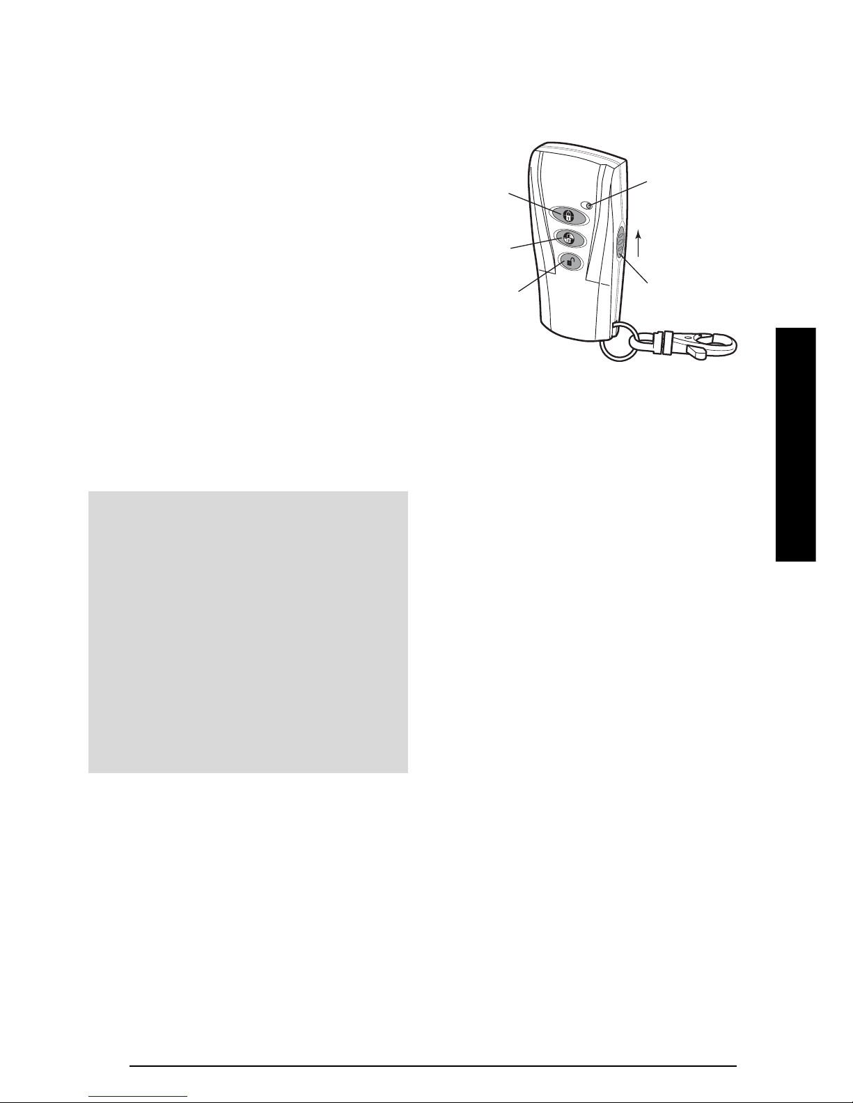
REMOTE CONTROL UNIT
The Remote Control Unit(s) are used to Arm, Part-Arm
and Disarm the system.
The Remote Control Unit also incorporates a Personal
Attack (PA) switch. Activating the PA switch on the
side of the Remote Control will immediately initiate a
Full Alarm condition whether the system is Armed or
Disarmed. The alarm can be cancelled by pressing
the ’DISARM’ button on the Remote Control or via the
Control Panel.
Any number of Remote Control Units can be used with
your system, providing they are all coded with the
system House Code.
The Remote Control is powered by a CR2032 type
Lithium cell which under normal conditions will have an
expected life in excess of 1 year. Under normal battery
conditions the LED on the Remote Control will only
illuminate when a button is pressed. However, under
low-battery conditions this LED will continue to flash
after the button has been released. When this occurs
the battery should be replaced as soon as possible.
CONFIGURING THE REMOTE
CONTROL
1. Remove the rear cover by undoing the small screw
on the rear of the Remote Control.
2. Select and record a random combination of ‘ON’
and ‘OFF’ positions for the DIP switches. This will
be the system House Code that enables all
elements of your transmitters to communicate
with the Control Panel.
IMPORTANT: The House Code for your system
should be changed from the factory default setting.
Slide up
to operate
Transmit LED
Personal Attack
Disarm
Arm
Part-Arm
IMPORTANT:
All system components must be set to the same
House Code.
As soon as installation is complete
- The default Master User Access Code (1234)
for the Control Panel should be changed to
your own code that only you know.
- User Access Codes 1-6 for the Control Panel
should be changed to your own codes that
only the relevant system user knows.
- The system Time and Date must be
configured.
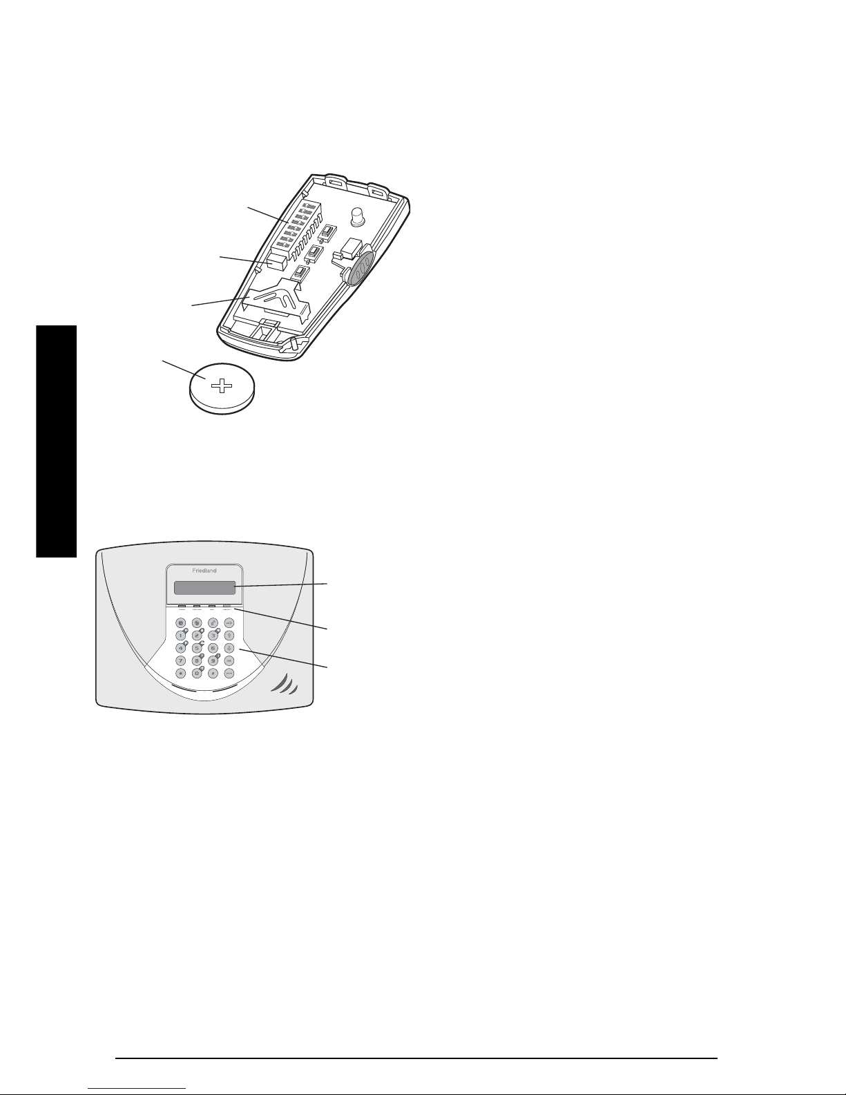
3. Ensure that the jumper link located immediately
below the House Code DIP switches is fitted in
position for use with this alarm system.
4. Insert the battery under the clip ensuring that the
+ terminal faces upwards away from the PCB.
5.
Replace the rear cover and fixing screw. Do not over
tighten the screw as this could damage the thread
.
CONTROL PANEL
Outside View of Control panel
POSITIONING THE CONTROL PANEL
When choosing a suitable location for the Control
Panel, the following points should be considered.
1.
The Control Panel should be located in a position out
of sight of potential intruders and in a safe location,
but easily accessible for system operation.
2.
The Control Panel should be mounted on a sound
flat surface to ensure that the rear tamper switch
on the Control Panel is closed when the Panel is
mounted. The Control Panel should be mounted
at a convenient height of between 1.5 and 2m and
in a position where it will be seen each day.
Note: If small children are in the household, a
further consideration should be given to keeping
the units out of their reach.
3. It is recommended that the Control Panel should
be positioned such that the Exit/Entry tone
(emitted by the Control Panel) can be heard from
outside the property.
4. The Control Panel should be mounted within a
protected area so that any intruder cannot reach the
Control Panel without opening a protected door or
passing through an area protected by a PIR
movement detector when the system is armed.
5. The Control Panel must be located within reach of
a mains socket.
6.
If the telephone based functionality is to be used
then the Control Panel will need connecting to a
convenient telephone point.
Note: It is recommended that the telephone
connection lead is not extended beyond 5m
before connecting to a telephone master or
secondary outlet.
7. Do not locate the Control Unit closer than 1m to
any large metallic object, (e.g. mirrors, radiators,
etc.) as this may affect the radio range of the
Control Panel.
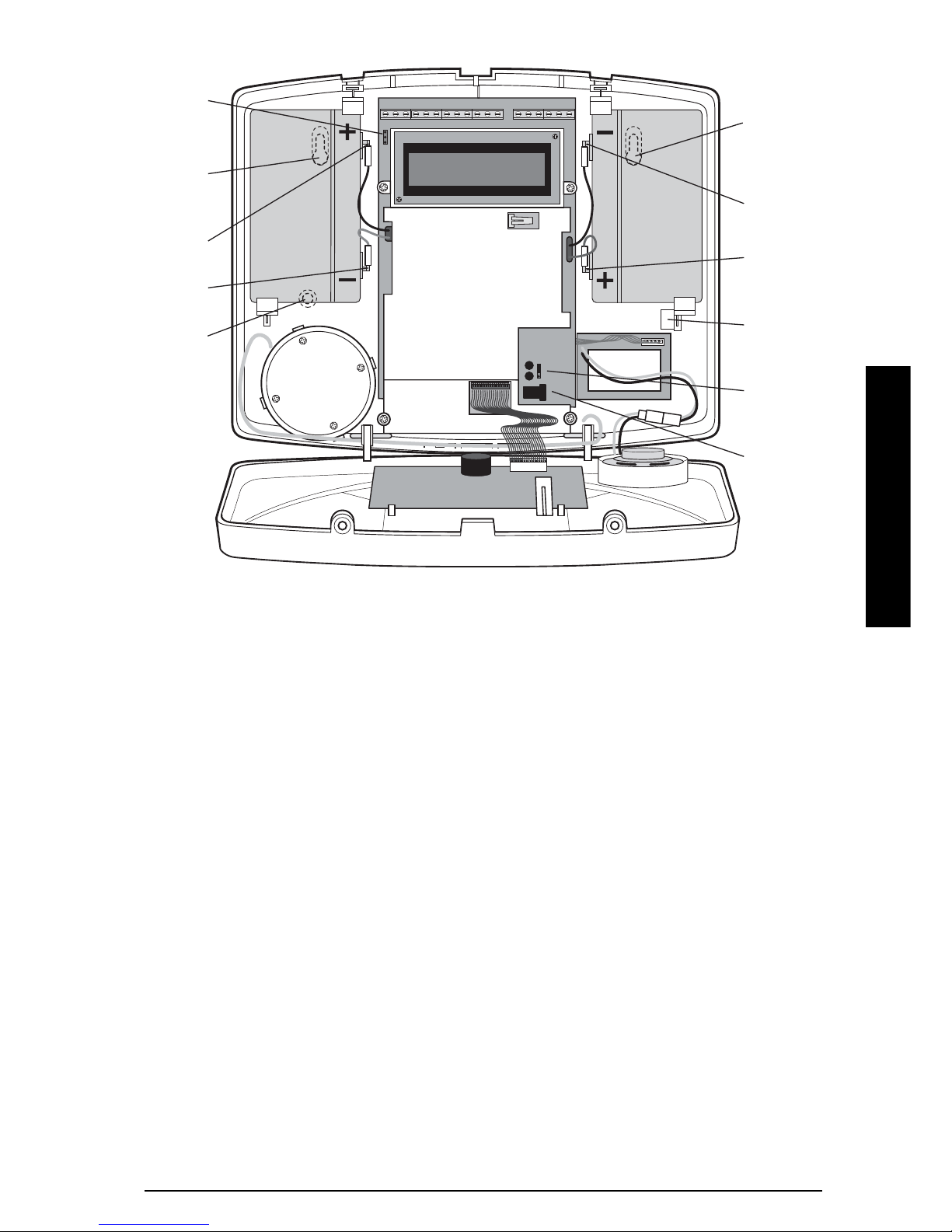
INSTALLING THE CONTROL PANEL
1. Undo the two captive fixing screws on top of the
panel and open the cover. The cover is hinged
along the bottom edge
2. Unclip and remove the two back-up batteries on
either side of the panel.
3. Hold the Control Panel in position on the wall and
mark the positions of the four fixing holes.
Remove the Panel and drill four 5mm holes and fit
the 25mm Wall Plugs.
Note: The wall plugs supplied with the product
are not suitable for plasterboard walls, if mounting
the Control Panel onto plasterboard use
appropriate wall plugs.
IMPORTANT: Do not drill the fixing holes with the
Control Panel in position as the resulting dust and
vibration may damage the Control Panel’s internal
components and invalidate the guarantee.
8 SA5
INSTALLATION
House Code
Dip Switches
Jumper Link
Battery Clip
Battery
LCD Display
Window
Status
Indicator LED
s
Keypad
SA5 9
INSTALLATION
4. Fit two 18mm No.4 screws into the top holes until
almost fully home and hang the Control panel over
these screws using the two keyhole slots in the
top corners of the panel casing.
5. Feed the connection plug and cable from the
Power Supply Unit into the Control Panel from the
rear through the cable entry hole below the battery
on the right of the panel and connect the plug to
the DC power socket. Ensure that the cable is not
trapped between the panel and the wall.
6. Fix the Panel to the wall using two 18mm No.4
screws in the lower two fixing holes in the panel
and tighten the upper fixing screws until they just
grip the casing. Do not over tighten the fixing
screws as this could damage or distort the casing.
7. Ensure that the "Reset" and the "Hard-Wired Siren
tamper detect" jumper links are set in the OFF
position.
8. Connect battery leads to both back-up batteries
and refit batteries.
Battery 1 (left): Red lead to
+ve battery
terminal
Blue lead to –ve battery
terminal
Battery 2 (right): Blue lead to +ve battery
terminal
Black lead to –ve battery
terminal
IMPORTANT: Take care when connecting battery
leads to the batteries as connecting incorrectly
could damage the batteries or the Control Panel.
Note: The Power LED may flash to indicate that
the unit is being operated from the back-up
batteries and that mains supply is not present.
9. If fitted, remove the plastic film covering the LCD
display and on the display window on the cover.
10. Close the lid of the Control Panel and tighten the
captive fixing screws.
11. Plug in and switch ON the Power Supply Unit, (the
Power LED should illuminate).
Upper Keyhole
Fixing Hole
– ve Terminal
(Black Lead)
+ ve Terminal
(Blue Lead)
Reset Jumper
Link P1
Power Supply
Jack Socket
Upper Keyhole
Fixing Hole
+ ve Terminal
(Red Lead)
– ve Terminal
(Blue Lead)
Lower Fixing
Hole
External Tamper
Switch Jumper
Link P51
Power Supply
Cable Access
Hole
T1 T2 GND T3 T4 N.C. CN.O.GNDGND BUZ BUTTAMP GND B+ V+ OUT GND
Inside View of Control Panel
10 SA5
INSTALLATION
12. If required, connect the Control Panel to the
telephone line using the cable supplied by
inserting small RJ11 plug into socket marked LINE
located on the bottom edge of the Control Panel.
If the cable supplied is not long enough to reach a
suitable phone point then it will need extending
using a coupler and extension lead (not supplied).
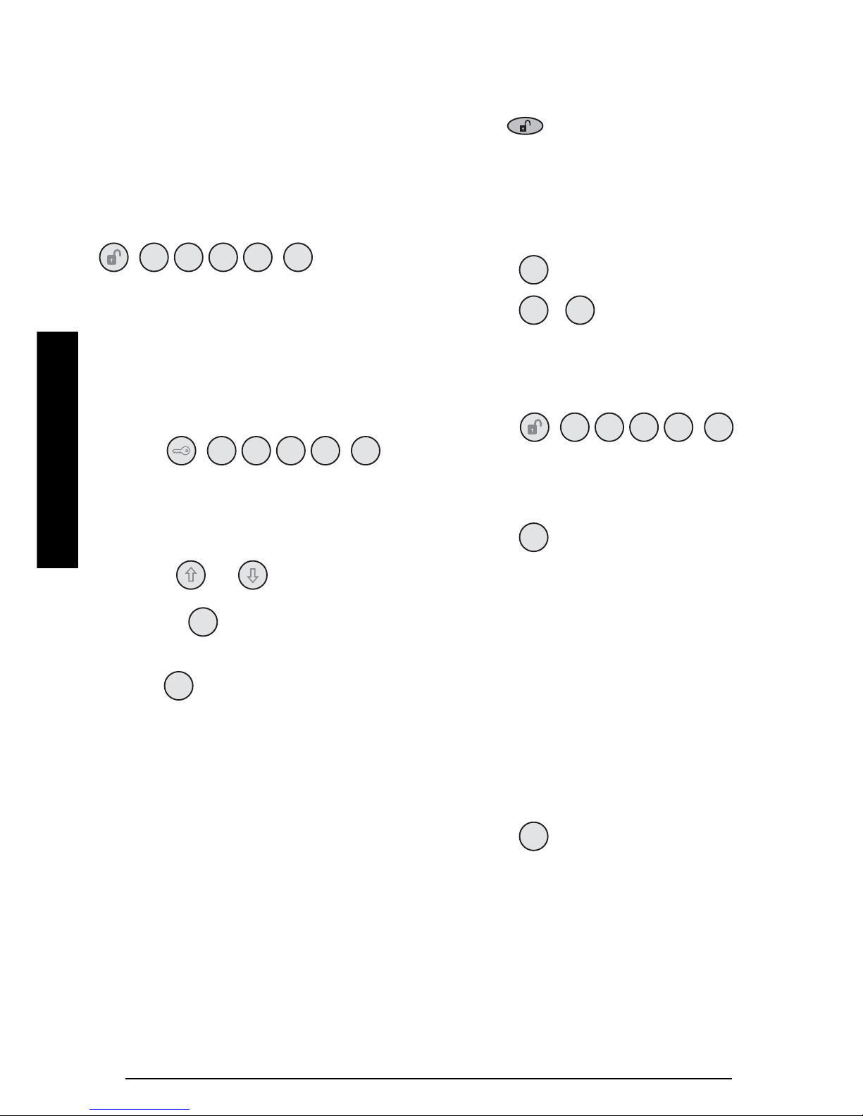
Note: If the Panel Tamper alarm sounds during the
installation reset the alarm by pressing:
, ,
on the Control Panel keypad.
CONFIGURING THE CONTROL PANEL
HOUSE CODE
With unit in Standby mode (Power LED only
illuminated).
1. Press , ,
‘1. USER SETUP’ will be displayed.
This puts the Control Panel into programming
mode.
2. Use the and buttons to scroll through
the menu until ‘2. SYSTEM SETUP’ is displayed
and press .
‘2-1 Learn House Code’ will be displayed.
3. Press .
The current House code setting will be displayed.
4. The new system House Code can be programmed
either directly at the Control Panel or via a Remote
Control Unit.
At the Control Panel:
Press buttons 1-8 on the Control Panel to
configure the display so that the required
house code is displayed on the screen. As
each button is pressed the corresponding
digit in the house code will change to the
opposite state, (“0” or “1”).
1=House Code DIP Switch On/Up
0=House Code DIP Switch Off/Down
Using a Remote Control:
With the required House Code already
configured on the Remote Control, press
.
The Control Panel will beep twice to
acknowledge the signal. The display will
change to show the received house code
on lower line of the display beneath the
corresponding DIP switch numbers (1-8).
5.
Press to save the new setting.
6.
Press , to return to Standby mode.
TESTING THE CONTROL PANEL
& REMOTE CONTROL
1. Press , ,
to put the system into Test mode.
‘TEST MODE – WALK TEST’ will be displayed.
2. Press to activate Walk Test.
‘Walk Test Waiting…’ will be displayed.
3. Press the buttons on the Remote Control in turn,
as each button is pressed the Control Panel will
beep and display the function of the button being
pressed on the screen.
4. Test the range of the Remote Control by pressing
the ‘DISARM’ button on the Remote Control from
in and around the property and from all locations
where you plan to install detectors. Check that
the Control Panel acknowledges the signal from
the Remote Control each time the ‘DISARM’
button is pressed.
5. Press to return to the top level menu of
TEST MODE.
User Access Code
1 234
ENTER
User Access Code
1 234
ENTER
Master User Access Code
1 234
ENTER
ENTER
ENTER
ENTER
ESC
ESC
ESC
ENTER

PASSIVE INFRA RED (PIR)
MOVEMENT DETECTORS
PIR detectors are designed to detect movement in a
protected area by detecting changes in infra-red
radiation levels caused for example when a person
moves within or across the devices field of vision. If
movement is detected an alarm signal will be
generated, (if the system is armed). PIR detectors will
also detect animals, so ensure that pets are not
permitted access to areas fitted with Passive Infra Red
Movement Detectors when the system is armed.
The Detector incorporates a tamper protection feature
to protect against attempts to interfere with the device.
If the battery cover is removed, an alarm will
immediately occur at any time.
The Detector also incorporates a sensitivity adjustment
feature to compensate for situations where the
detector may be affected by environmental changes,
(e.g. insects, air temperature, etc).
To conserve power and maximise battery life the PIR
detector will only detect movement if there has been
no movement detected within the previous 2 minutes.
The PIR Detector is powered by a PP3 Alkaline battery
which under normal conditions will have an expected
life in excess of 1 year. When the battery level drops,
with the PIR in normal operation mode and the battery
cover fitted, the LED behind the detection window will
flash. When this occurs the battery should be replaced
as soon as possible. (Note: in normal operation with
the LED behind the lens will not flash on detection of
movement).
Any number of PIR Movement Detectors can be used
with your system, providing they are all coded with the
system House Code and are mounted within effective
radio range of the Control Panel.
POSITIONING THE PIR MOVEMENT
DETECTORS
The recommended position for a PIR Movement
Detector is in the corner of a room mounted at a height
between 2 and 2.5m. At this height, the detector will
have a maximum range of up to 12m with a field of
view of 110°.
Detection Zone Pattern for PCB in position 5
The Position of the PCB inside the PIR can be set to 5
different positions to adjust the range of the detection
pattern created by the PIR. Setting the PCB in position
3 will reduce the range to approximately 9m, with
position 1 providing a range of approximately 6m. The
recommended position setting for the PCB is in
position 5.
When considering and deciding upon the mounting
position for the detector the following points should be
considered to ensure trouble free operation:
●
Do not position the detector facing a window or
where it is exposed to or facing direct sunlight. PIR
Movement Detectors are not suitable for use in
conservatories.
●
Do not position the detector where it is exposed to
draughts.
●
Do not position the detector directly above a heat
source, (e.g. fire, radiator, boiler, etc).
●
Where possible, mount the detector in the corner of
the room so that the logical path of an intruder
would cut across the fan detection pattern. PIR
detectors respond more effectively to movement
across the device than to movement directly
towards it.
●
Do not position the detector in a position where it is
subject to excessive vibration.
INSTALLATION
SA5 11
2m - 2.5m
23416785910
Detector Range (metres)
5m
110°
180°
10m
3m
INSTALLATION
12 SA5
●
Ensure that the position selected for the PIR
detector is within effective range of the Control
Panel, (refer to "Testing the Control Panel & Remote
Control").
Note: When the system is Armed, pets should not be
allowed into an area protected by a PIR Detector as
their movement would trigger the PIR and trigger an
alarm.
Note: DO NOT fix the detector to metalwork or locate
the unit within 1m of metalwork (i.e. radiators, water
pipes, etc) as this could affect the radio range of the
Device.
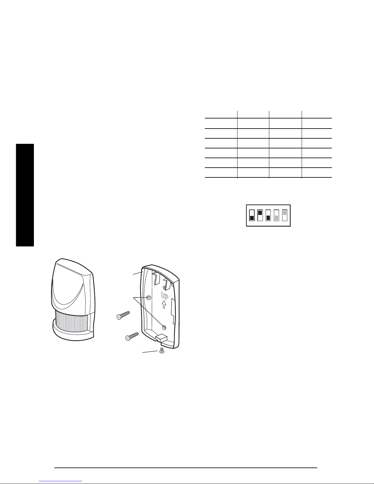
INSTALLING AND CONFIGURING THE
PIR MOVEMENT DETECTORS
Ensure that the system is in Test mode, (see page 15).
1. Undo and remove the fixing screw from the
bottom edge of the PIR. Carefully pull the bottom
edge of the detector away from the rear cover and
then slide down to release the top clips.
2. Carefully drill out the required mounting holes in
the rear cover using a 3mm drill according to
whether the unit is being mounted in a corner or
against a flat wall.
3. Using the rear cover as a template, mark the
positions of the fixing holes on the wall.
4. Fix the rear cover to the wall using the two 18mm
No.4 screws and 25mm wall plugs, (a 5mm hole
will be required for the wall plugs). Do not overtighten the fixing screws as this may distort or
damage the cover.
Note: The wall plugs supplied with the product
are not suitable for plasterboard walls, if mounting
the Detector Panel onto plasterboard use
appropriate wall plugs.
5. Configure the House Code for the PIR Detector by
setting DIP switches 1-8 of SW2 to the same
ON/OFF combination as the House Code DIP
switches in all other system devices.
6. Configure the alarm zone which the detector will
operate on by setting DIP switches 1-3 of SW3 as
follows:
DIP 1 DIP 2 DIP 3
Zone 1 OFF OFF OFF
Zone 2 OFF OFF ON
Zone 3 OFF ON OFF
Zone 4 OFF ON ON
Zone 5 ON OFF OFF
Zone 6 ON OFF ON
e.g. To configure the detector to operate on Zone
3 set DIP switches 1, 2 and 3 of SW3 as follows:
7. DIP 4 of SW3 is used to configure the PIR Detector
for walk test mode, which allows the operation of
the detector to be checked during installation
without triggering a Full Alarm.
ON Walk Test mode
OFF Normal operation
Note: On initial installation the detector should be
configured into Walk-Test mode ready for testing.
8. To select the required sensitivity, set DIP 5 of SW3
as follows:
ON HIGH Sensitivity
OFF LOW Sensitivity
Note: The recommended setting is HIGH.
However, in cases of extreme environmental
problems or if unexplained false alarms are
experienced, it may be necessary to set the
sensitivity to LOW. Setting the device to LOW
sensitivity will require a greater amount of
movement in order to trigger the device.
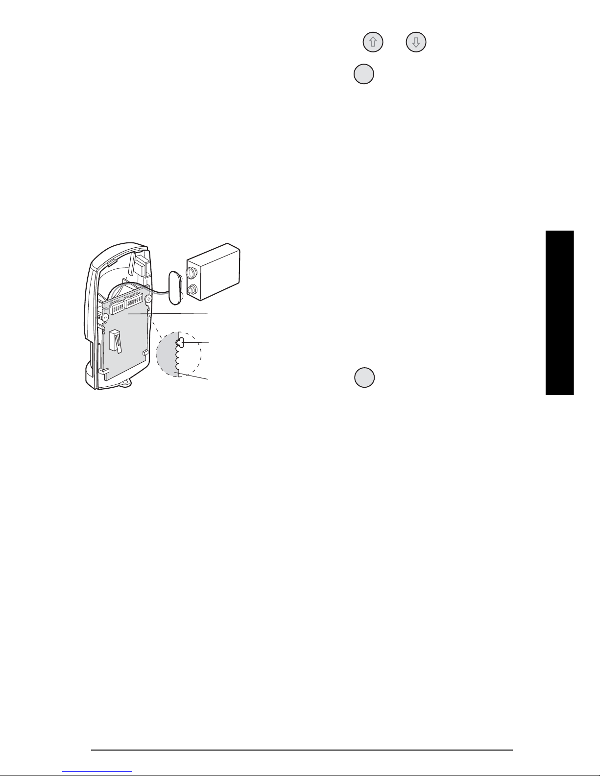
9. Connect the PP3 Alkaline battery to the battery
clip. The LED behind the lens will rapidly flash for
approximately 2-3 minutes until the PIR has
Mounting
Hole
Positions
Fixing Screw
Rear Cover
ON
1 2 3 4 5
INSTALLATION
SA5 13
stabilised. The LED will then stop flashing and
turn OFF.
Note: If the device is configured in Walk Test
mode (i.e. DIP 4 of SW3 ON) then the LED will
flash upon detection of movement after the warm
up period has expired.
10. Check that the detector PCB is located and set in
the correct position to give the detection zone
pattern required.
To adjust the PCB position simply slide it up or
down ensuring that the location legs are aligned
with the required position number marked on the
board.
PCB Position Detection Range
16m
39m
5 12m
11. Refit the PIR detector to the rear cover by offering
the detector up to the rear cover and locate the
clips in the top edge into the rear cover. Push the
lower edge of the detector into place and refit the
fixing screw in the bottom edge of the PIR to
secure in position. Do not over-tighten the fixing
screws as this may damage the casing.
TESTING THE PIR MOVEMENT
DETECTORS
Ensure that the system is in Test mode, (see page 17).
Ensure that the PIR is configured in Walk Test mode, (i.e.
DIP 4 of SW3 ON) and mounted in position on the wall.
Allow 2-3 minutes for the detector to stabilise before
commencing testing.
1. Use the and buttons to scroll through
the menu until ‘WALK TEST’ is displayed and
press .
‘Walk Test Waiting…’ will be displayed.
2. Walk into and move slowly around the protected
area, each time the detector senses movement the
LED behind the lens will flash. In addition, the
Control Panel will beep to indicate that the alarm
signal has been received and the identity of the
zone that the detector is configured for will be
displayed.
If necessary adjust the detection range by
changing the mounting position of the PCB within
the PIR housing.
Note: In normal operation, the LED behind the
PIR lens will not flash on movement detection,
(unless the battery is low).
3.
Remove the back cover of the PIR detector. The
Control panel should beep and display "Accessory
Tamper" to show that the detector's tamper switch
has been activated.
4.
Press to return to the top level menu of
TEST MODE.
5. Reconfigure the PIR Detector for Normal
operation mode by setting DIP4 of SW3 to OFF
and refit in position.
Note: When the detector is fully installed i.e. battery
cover is refitted, to conserve power and maximise
battery life the PIR detector will only detect
movement if there has been no movement detected
within the previous 2 minutes.
Dip Switches
(SW2 and SW3)
PCB Board
(slides up and down
to adjust position)
5
4
3
2
1
PCB Position
Indicator
(positions 1-5)
O
N
1
2
3
4
5
6
7
8
O
N
1
2
3
4
5
S
W
3
S
W
2
ENTER
ESC
 Loading...