

Page 1

Thermozone WAC 200
SE ........ 10 GB ........ 23
NO ........ 14 DE ........ 26
Page 2
Thermozone WAC 200
2
Page 3
Thermozone WAC 200
3
Page 4

Thermozone WAC 200
Airflow Air in Power Air out Waterflow Pressure drop Water out
Luftflöde Luft in Effekt Luft ut Vattenflöde Tryckfall Vatten in
Luftmengde Luft inn Effekt Luft ut Vannmengde Trykkfall Vann ut
Luftvolumenstrom Luft ein Leistung Luft aus Wasserdurchfluß Druckabfall Wasser aus
4
Page 5

Thermozone WAC 200
5
Page 6

Thermozone WAC 200
*) For surrounding temperatures, from which the Thermozone draws air, other than 15 °C it is
necessary to multiply the output (P
10°C x1.08
15°C x1.00
20°C x0.92
25°C x0.84
6
) with hte following factors:
tot
Page 7

Thermozone WAC 200
Installation and Operating Instructions
Application area
Frico Thermozone WAC 200 is an air curtain unit
intended for permanent installation above
entrance doors and smaller doors up to 3 meters.
The efficiency of the curtains is dependent on the
size of the load on the door in question.
Thermozone WAC 200 is supplied with a hot water
heating coil and is mounted above the door.
Protections class IP44.
Operation
Air is drawn in from the front of the unit and is
blown out downwards so that is screens the door
opening and minimises any heat leakage through
it. The air speed is adjusted in two stages using the
speed selector.
Note that if there is negative pressure in the
building the efficiency if the air curtain is
significantly reduces. Ventilation should be
balanced.
GB
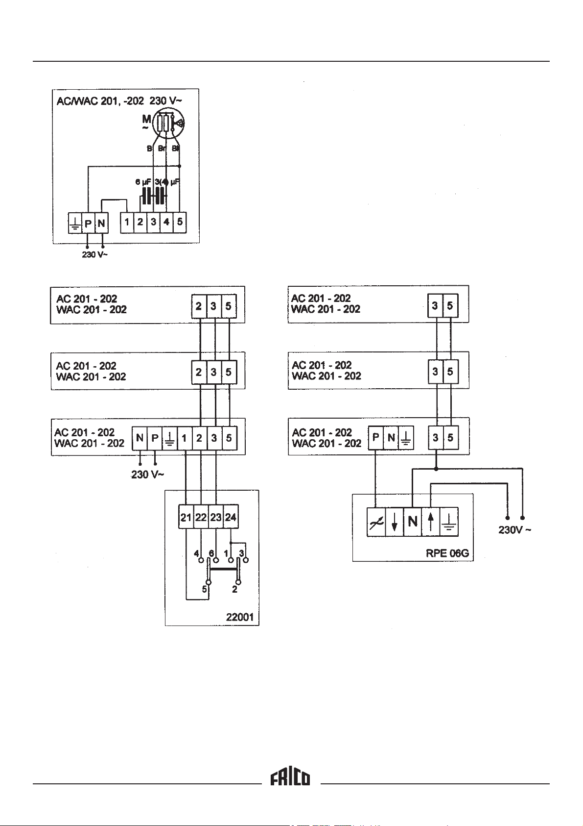
Electrical installation WAC
The electrical connection to the fan motors is
made using a lead with a plug, which is connected
to an appropriate 230 V~ socket. One of the
knockouts located on the top of the unit is used to
enter the control cable. Connection of the control
cable may only be carried out by a qualified
technician. There are several different options for
controlling the speed of the motors. See the wiring
diagram.
Connection of the water coil
Installation should be carried out by a qualified
technician and in accordance with applicable
directives. The connections DN 15 (1/2") with
internal threads can be found in top of the unit.
The plug for emptying the water is located in the
connection area on the lower part if the inlet pipe.
The connection area is accessible once the front
grille has been removed.
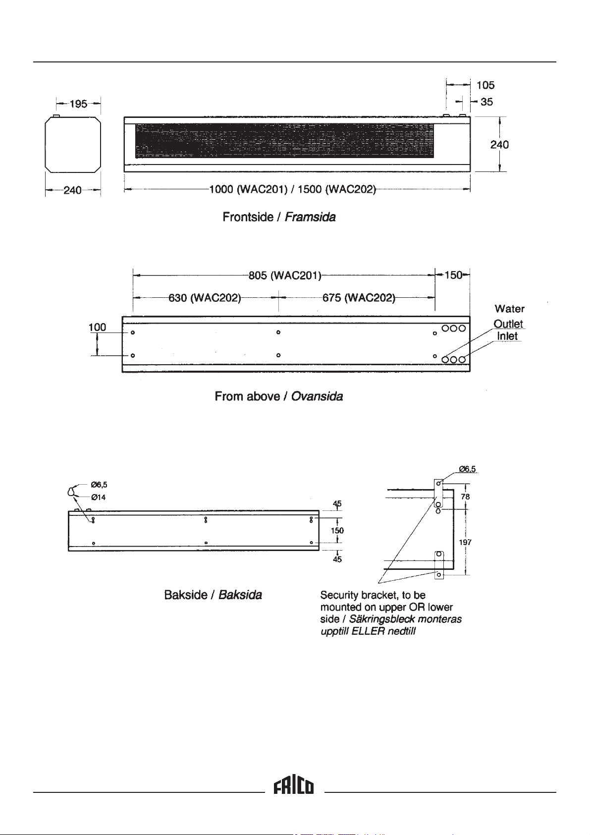
Assembly
The unit may only be installed horizontally with a
downward output air direction. Several units can
be fitted side-by-side across the wide door
openings. The unit may be installed as close to the
ceiling as possible. The only limitation is the pipe
connections. For other dimensions and minimum
assembly distances, see fog.
a) Fitted on the wall or beam
• The thermozone hangs from two keyhole slots,
three on WAC 202, located on the rear of the
unit. Suitable bolts could be M6S M6. NOTE!
The unit must be secured using the keyhole
slots. The strip can be fitted either facing
upward or downward, see the detail fig.
• Thermozone can be bolted directly to the wall/
beam. There are four M6 blind nuts, six on
WAC 202, located on the rear of the unit for this
purpose.
b) Suspended using drop rods
There are four, six on WAC 202, M10 blind nuts
on top of the unit for securing drop rods, with
paired centre-to-centre spacing of 100 mm, see
fig. Brackets for suspended mounting are
available as accessories.
Safety
Ensure the area around the unit’s intake and
exhaust grilles is kept from material that can
prevent the air flow through the unit.!
During operation the surfaces of the unit are hot!
Maintenance
As the fan motors and other components are
maintenance free no maintenance is necessary
other than cleaning when required, however, at
least once a year. WAC units are equipped with a
filter that protects against contamination and
blockage. The filter should be cleaned regularly to
ensure the curtain effect and heating output
produced from the unit.
Water control
VR 20 together with a thermostat, e.g. KRT 1900 is
a good solution for controlling the heat in WAC. A
VR consists of four components and should be
fitted as set out in the figure below, also see the
detail manuals found in respective VR sets.
1.Shutoff valve
2.Trimming valve with shutoff option
3.Three-way motor valve
4.Bypass valve
VR20 has DN 20 (3/4") connections, except the
bypass valve that has DN 10 (3/8").
11
Page 8

GB
Thermozone WAC 200
Documenting the output, pressure, and flow
requirement
There are three different documenting methods.
1. Given water temperatures:
WAC is documented here with the desired water
temperatures on supply and return pipes. The air
flow through the WAC is given by the speed of the
fans. The highest and lowest speeds are
documented. Output data from this table are
output, required water flow and the pressure drop
on the water side. The air temperature from the air
curtain is also presented.
2 . Given water flow and input temperature of
the water:
WAC is documented here based on a pressure drop
of 10 kPa across the coil. At this pressure drop a
specific quantity of water can be pushed through
the coil. Output data is output, temperature of the
output air and the return water temperature.
3 . WAC + VR:
WAC with VR control is documented here. The
valve set can be connected to several WAC units
and are documented here with different
combinations based on the width if the door. There
are two different dimensions for VR. VR20 has
connection thread DN20 (3/4") and VR25 is
connected with DN25 (1"). VR25 has a lower
pressure drop than VR20 and can therefore be
used when a greater flow is required. In this
presentation the air temperature is locked in the
WAC at 15°C and the pressure drop across the
entire VR set +WAC is set to 15 kPa.
For surrounding temperatures, from which the
Thermozone draws air, other than 15°C it is
necessary to multiply the output (P
following factors:
Air temperature Factor
10°C 1,08
15°C 1,00
20°C 0,92
25°C 0,84
) with the
tot
Type WAC 201 WAC 202
Voltage, motor/control V 230V~ 230V~
Current intensity, motor/control A 0,4 0,6
Airflow m³/h 600/900 1000/1400
Water volume l 0,6 1,3
Sound level dB(A) 42/51 44/53
Weight kg 18 25
Length mm 985 1500
Max. working pressure (water coil), 100°C bar 1 6 1 6
Protection class IP44 IP44
Accessories Designation
Control panel (2 stage) 22001
Variable speed control RPE 06G
Valve set for WAC VR20
Thermostat KRT1900
Suspended ceiling grille (1192 x 192) 22003
Suspended ceiling grille (1515 x 192) 22004
12
Page 9

Thermozone WAC 200
Tillverkardeklaration/
EU-försäkran om överensstämmelse
Declaration of Conformity
Vi
Frico AB
Box 102
S-433 22 Partille
intygar härmed att följande produkter:
Luftridåer serie Thermozone AC-200
Type: AC-201, WAC-201, AC-202 och
WAC-202
AC-203, AC-206 och AC-209
AC-205 och AC-210
Uppfyller kraven enligt följande direktiv:
EC Elektromagnetisk Kompatibilitet (EMC)
Direktiv 89/336 /EEC & 92/31 EEC
EC Lågspänningsdirektiv (LVD) 73/23/EEC
Och är tillverkade enligt följande standarder:
EMC: EN 55 014: 1993
EN 60 555-2/3: 1991
EN 55 104
We
Frico AB
Box 102
S-433 22 Partille
under own responsibility hereby declare that the
following product(s)
Air-curtains series Thermozone AC-200
Type: AC-201, WAC-201, AC-202 and
WAC-202
AC-203, AC-206 and AC-209
AC-205 and AC-210
which is(are) covered by this declaration of
conformity comply with the
EC Electromagnetic Compatibility (EMC)
Directive 89/336 /EEC & 92/31 EEC
EC Low Voltage Directive (LVD) 73/23/EEC
and is(are) manufactured in accordance with the
following stated harmonised standard(s) or other
normative document(s).
LVD: CCA HD 251 S3:1982 inkl. Am. 1-3
CCA HD 251 S1:1987 inkl.. Am. 1-4
Partille , 15 December 1995
Mats Careborg
Teknisk Chef
EMC: EN 55 014: 1993
EN 60 555-2/3: 1991
EN 55 104
LVD: CCA HD 251 S3:1982 incl. Am. 1-3
CCA HD 251 S1:1987 incl. Am. 1-4
Partille , 15 December 1995
Mats Careborg
Technical Manager
15
Page 10

Main office
FRICO AB Tel: +46 (0)31 336 86 00
Box 102 Fax: +46 (0)31 26 28 25
S-433 22 Partille e-mail: mailbox@frico.se
SWEDEN http://www.frico.se
France
FRICO FRANCE Tel: +33 (0) 1 30 61 23 68
7, rue de la libération Fax: +33 (0) 1 39 73 72 26
F-69 270 Fontaines sur Saone e-mail: info@frico.fr
FRANCE
Norway
FRICO AS
Postboks 82, Alnabru Tel: +47 (0)2 272 38 44
N-0614 Oslo Fax: +47 (0)2 272 38 39
NORWAY e-mail: mailbox@frico.no
http://www.frico.no
Russia
FRICO representative office in Russia
1 st Golutvinsky per., 3 Tel/Fax: +7 095 238 63 20
Moscow 109180 e-mail: frico@orc.ru
RUSSIA
 Loading...