

Page 1
VLSP
.... 2
SE
.... 9
GB
SD230
AV
BPV10
SD230
TAC
AV
BPV10
.... 16
NO
.... 23
DE
.... 30
FR
.... 37
NL
.... 44
ES
.... 51
RU
TAC
Page 2
VLSP
9
GB
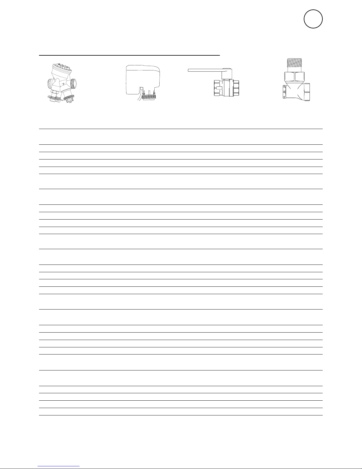
Components
VLSP, pressure independent valve kit on/off
SD230
AV
BPV10
TAC (TA Compact-P)
Type Specification
TAC15LF Two way pressure independent regulation and adjustment valve Low flow, DN15
SD230 Actuator on/off 230V 230V~
AV15 Shut off valve DN15
BPV10 By-pass valve DN10
VLSP15LF
Type Specification
TAC15NF Two way pressure independent regulation and adjustment valve Normal flow, DN15
SD230 Actuator on/off 230V 230V~
AV15 Shut off valve DN15
BPV10 By-pass valve DN10
VLSP15NF
Type Specification
TAC20 Two way pressure independent regulation and adjustment valve Normal flow, DN20
SD230 Actuator on/off 230V 230V~
AV20 Shut off valve DN20
BPV10 By-pass valve DN10
VLSP20
Type Specification
TAC25 Two way pressure independent regulation and adjustment valve Normal flow, DN25
SD230 Actuator on/off 230V 230V~
AV25 Shut off valve DN25
BPV10 By-pass valve DN10
VLSP25
Type Specification
TAC32 Two way pressure independent regulation and adjustment valve Normal flow, DN32
SD230 Actuator on/off 230V 230V~
AV32 Shut off valve DN32
BPV10 By-pass valve DN10
VLSP32
Page 3
VLSP
10
GB
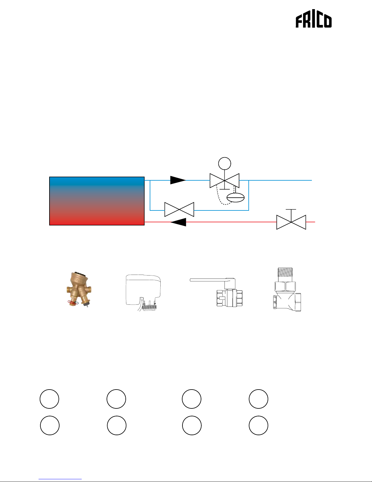
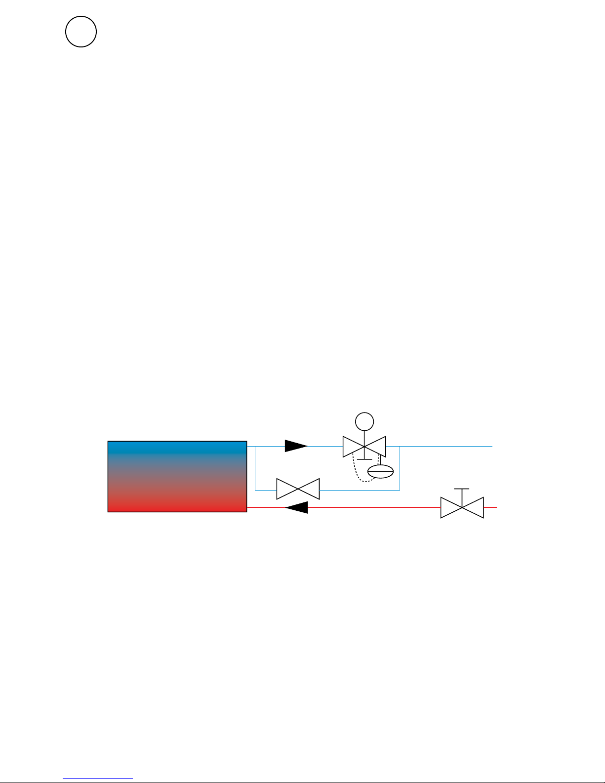
VLSP, pressure independent
valve kit on/off
Two way pressure independent control and
adjustment valve with on/off actuator, shut-off
valve and bypass. DN15/20/25/32. 230V.
The valve set consists of the following:
• TAC, pressure independent regulation and
adjustment valve
• SD230, actuator on/off 230V
• AV, shut off valve
• BPV10, bypass valve
The shut off valve (AV) consists of a ball valve
which is either open or closed and is used to
shut off the flow, when servicing for example.
The regulation and adjustment valve (TAC)
can be used to finely adjust or shut off the
water flow manually. TAC is independent
of the available differential pressure, which
contributes to stable and accurate regulation
(ensures the correct flow to the heater even if
the differential pressure in the rest of the pipe
system changes). The water flow is set using
the gray adjustment knob on the valve
If the valve (TAC) is closed, a low flow
passes through the by-pass valve (BPV10) so
that there is always hot water in the water
coil. This is to provide quick heat supply
when a door is opened but also to provide a
degree of frost protection.
The actuator (SD) controls the heat supply
on/off. In unpowered mode SD230 is open.
The valve set is available in 4 different
valve dimensions, DN15 (1/2"), DN20 (3/4"),
DN25 (1") and DN32 (1 1/4"). The by-pass
valve is DN10 (3/8").
Used with SIRe Basic and Competent or
supplemented with suitable thermostat.
SD230
TAC
BPV10
Page 4
VLSP
11
GB
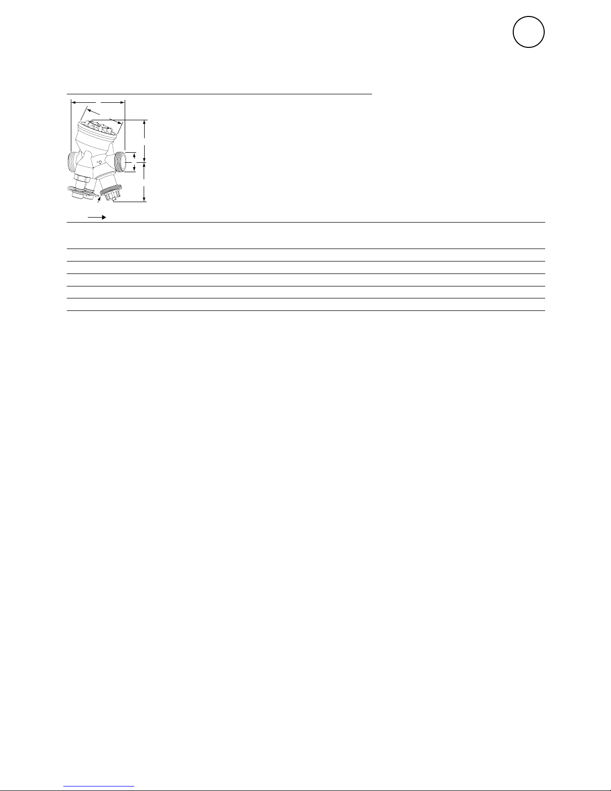
Two way pressure independent regulation and adjustment valve TAC (TA
Compact-P)
Type DN Flow D Da
*1
L
[mm]H1[mm]H2[mm]B[mm]
Vikt
[kg]
TAC15LF 15 Low flow G3/4 M30x1,5 74 55 55 54 0,54
TAC15NF 15 Normal flow G3/4 M30x1,5 74 55 55 54 0,54
TAC20 20 Normal flow G1 M30x1,5 85 64 55 64 0,69
TAC25 25 Normal flow G1 1/4 M30x1,5 93 64 61 64 0,79
TAC32 32 Normal flow G1 1/2 M30x1,5 11 2 78 61 78 1,5
Pressure class: PN16
Max. working temperature: 90 °C
Min. working temperature: 0 °C
Lift: 4 mm
*1
) Connection to actuator.
Dimensions and technical specifikations
Material
AMETAL® is a dezincification resistant alloy.
Media:
Water or neutral fluids, water-glycol
mixtures.
Flow range
:
The flow (q
max
) can be set within the
range:
DN 15 LF: 44-245 l/h
DN 15 NF:88-470 l/h
DN 20: 210-1150 l/h
DN 25: 370-2150 l/h
DN 32: 800 - 3700 l/h
q
max
= l/h at each setting and fully open
valve plug.
Differential pressure (DpV):
Max. differential pressure (DpV
max
):
400 kPa = 4 bar
Min. differential pressure (DpV
min
):
DN15, DN20 = 15 kPa = 0,15 bar
DN25, DN32 = 23 kPa = 0,23 bar
(Valid for position 10, fully open. Other
positions will require lower differential
pressure.)
DpV
max
= The maximum allowed pressure
drop over the valve, to fulfi ll all stated
performances.
DpV
min
= The minimum recommended
pressure drop over the valve, for proper
differential pressure control.
L
D
H2
M30x1.5*
ØB
H1
Da
Valve body: AMETAL®
Valve insert: AMETAL®
Valve plug: Stainless steel
Spindle: Stainless steel
Spindle seal: EPDM O-ring
Dp insert: PPS
Membrane: EPDM and HNBR
Springs: Stainless steel
O-rings: EPDM
Page 5

VLSP
12
GB
Measuring
Measuring q
1. Remove any actuator.
2. Connect IMI TA* balancing instrument to
the measuring points.
3. Input the valve type, size and setting and
the actual flow is displayed.
Measuring DH
1. Remove any actuator.
2. Close the valve according to “Shut-off”.
3. Bypass the Dp part by opening the bypass
spindle ≈1 turn anticlockwise, with a 5 mm
Allen key.
4. Connect IMI TA* balancing instrument to
the measuring points and measure.
Important! Close the bypass spindle after the
measurement is completed.
Leakage rate:
Leakage flow ≤ 0,01% of max. q
max
(setting 10)
and correct flow direction.
(Class IV according to EN 60534-4).
Connection:
Male thread according to ISO 228.
Marking
TA, IMI, PN 16, DN and flow direction
arrow. Grey setting wheel: TA-COMPACT-P
and DN. For low flow version also LF.
Application
The regulation and adjustment valve (TAC)
can be used to finely adjust or shut off the
water flow manually. TAC is independent
of the available differential pressure, which
contributes to stable and accurate regulation
(ensures the correct flow to the heater even if
the differential pressure in the rest of the pipe
system changes). The water flow is set using
the gray adjustment knob on the valve.
Functions
• Control
• Pre-setting (max. flow)
• Differential pressure control
• Measuring (DH, T, q)
• Shut-off
Noise
In order to avoid noise in the installation
the valve must be correctly installed and the
water de-aerated.
* www.imi-hydronic.com/
Page 6

VLSP
13
GB
Setting
1. Turn the setting wheel to desired value, e.g. 5.0.
Sizing
1. Choose the smallest valve size that can
obtain the design flow with some safety
margin, see “q
max
values”. The setting
should be as open as possible.
2. Check that the available DpV is within the
working range 15-400 kPa or 23-400 kPa.
Measuring accuracy
Maximum flow deviation at different settings.
*) Setting (%) of fully open valve.
Shut-off
1. Turn the setting wheel clockwise to X.
0
2
4
6
8
10
12
14
16
18
20
22
24
02040608
0100
[%] *
± %
10 30 50 70 90
q
max
values
1 2 3 4 5 6 7 8 9 10
DN15LF 44 71 97 123 148 170 190 210 227 245
DN15 88 150 200 248 295 340 380 420 450 470
DN20 210 335 460 575 680 780 890 990 1080 11 5 0
DN25 370 610 830 1050 1270 1490 1720 1870 2050 2150
DN32 800 1220 1620 2060 2450 2790 3080 3350 3550 3700
Position
q
max
= l/h at each setting and fully open valve plug.
LF = Low flow
Page 7

VLSP
14
GB
Closing force
Working range: X (closed - fully open) =
11,6 - 15,8
Closing force: Min. 125 N (max. 500 N)
The maximum recommended pressure drop
over a valve and actuator combination for
close off (DpV
close
) and to fulfill all stated
performances (DpV
max
).
kPa*
DN15 400
DN20 400
DN25 400
DN32 400
*) Closing force 125 N.
DpV
close
= The maximum pressure drop that
the valve can close against from an opened
position, with a specified force (actuator)
without exceeding stated leakage rate.
DpV
max
= The maximum allowed pressure
drop over the valve, to fulfill all stated
performances.
Ø22
10
X
M30x1,5
Shut off valve (AV15/20/25/32)
Dimensions and technical specifikations
A
B
C
D
Application
The shut off valve is used to shut off the water
flow to the unit and consists of a ball valve
which is either open or closed. The shut off
valve have no adjustment function and is only
used for maintance and service.
Type DN A
[mm]B [mm]C [mm]D [mm]
Weight
[kg]
AV15 15 119 57 25 57 0,2
AV20 20 130 57 32 70 0,3
AV25 25 140 62 42 85 0,3
AV32 32 178 81 57 104 0,5
Page 8

VLSP
15
GB
By-passvalve (BPV10)
Dimensions and technical specifikations
Type HxWxD
[mm]
Weight
[kg]
BPV10 63x45x28 0,17
Application
The by-pass valve is used when a small
amount flow of water should pass by the unit
at all times. The purpose of this is that the
water should always stay hot in the watercoil,
in cases when a door opens and a quick heat
supply is needed.
This kind of valve has the dimension
DN10 (3/8").
When mounting the plug inside the
valve must be screwed entirely at first
and then screwed back a whole lap. In cases
where the distance between inlet and the
unit is far away, open the plug even more by
screwing the plug backwards.
Actuator (SD230)
Dimensions and technical specifikations
Application
The electrical actuator in combination
with the valve is used for regulating the heat
supply to the unit. It's function is to open or
close the valve (on/off). In unpowered mode
SD230 is open.
The electrical actuator can be mounted and
rotated after that the valve has been installed.
For regulating the actuator in
combination with valve complement with
SIRe or appropiate thermostat.
Action
On/Off-regulation, linear
motion
Supply voltage 230V, 50-60 Hz
Power consumption <1,5 VA in operation
<0,5 VA in the end position
Stroke force 100 N
Stroke length 6,5 mm
Full stroke time "On" Nominal 3 s
Full stroke time "Off" Nominal 12 s
Protection class IP54
Screw-nut M30x1,5
Cable length 1,5 m
Isolation class II
Surrounding temp. 0-60 °C
Type HxWxD
[mm]
Weight
[kg]
SD230 81x88x56 0,2
!
SPST
L
N
BLACK
BROWN
BLUE
max. 40 m
BROWN
BLACK
L
N
BLUE
SPST
CONTROLLER
Page 9

Page 10

Page 11

Main offi ce
Frico AB Tel: +46 31 336 86 00
Box 102
SE-433 22 Partille mailbox@frico.se
Sweden www.frico.se
For latest updated information and information
about your local contact: www.frico.se
Art no: E4593, 20161026 HH
 Loading...