

Page 1
Original instructions
UF600
GB
FR
PL
.... 13
.... 27
.... 43
SE
IT
RU
.... 16
.... 31
.... 47
.... 19
DE
.... 35
NL
Appendix A
.... 51
ES
NO
.... 23
.... 39
Page 2

UF600
GB
SE
DE
ES
FR
The introduction pages consist mainly of pictures. For translation of the
English texts used, see the respective language pages.
Introduktionssidorna består huvudsakligen av bilder. För översättning av de
engelska texter som används, se respektive språksidor.
Die Einleitungsseiten bestehen hauptsächlich aus Bildern. Für die Übersetzung
der verwendeten Texte in englischer Sprache, siehe die entsprechenden
Sprachseiten.
Las páginas introductorias contienen básicamente imágenes. Consulte la
traducción de los textos en inglés que las acompañan en las páginas del
idioma correspondiente.
Les pages de présentation contiennent principalement des images. Pour la
traduction des textes en anglais, consultez la page correspondante à la langue
souhaitée.
IT
NL
NO
PL
RU
Le pagine introduttive contengono prevalentemente immagini. Per le
traduzioni dei testi scritti in inglese, vedere le pagine nelle diverse lingue.
De inleidende pagina's bevatten hoofdzakelijk afbeeldingen. Voor een vertaling
van de gebruikte Engelse teksten, zie de pagina's van de resp. taal.
Introduksjonssidene består hovedsakelig av bilder. For oversettelse av de
engelske tekstene, se de respektive språksidene.
Początkowe strony zawierają głównie rysunki. Tłumaczenie wykorzystanych
tekstów angielskich znajduje się na odpowiednich stronach językowych.
Страницы в начале Инструкции состоят в основном из рисунков, схем и
таблиц. Перевод встречающегося там текста приведен в разделе RU.
2
Page 3
UF600
Outdoor installation Indoor installation
1.
500/630
1.
500/630
240/290
810/1015
2.
750/900
14801080/15001000
3.
4.
5.
6.
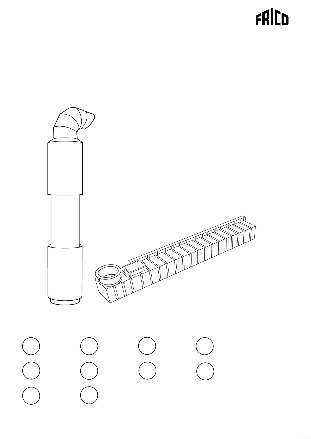
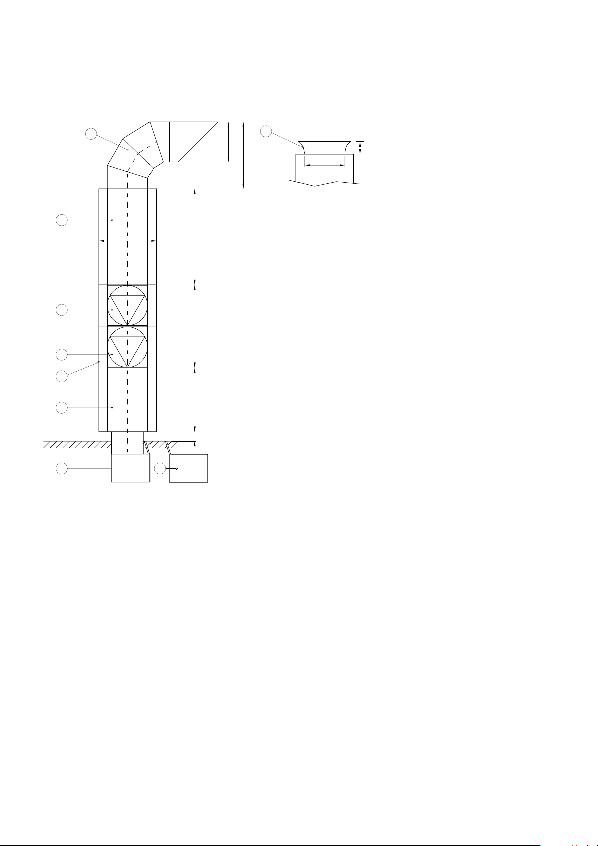
1. Intake with bird protection grille (or inlet nozzle for
indoor installation)
2. Inlet side silencer
L = 1 480 mm
3. Axial fan 400V
4. Axial fan 400V
5. Motor silencer
6. Silencer pressure side
L = 1 000 mm
7. Floor channel
7.
Outdoor
installation
Fig. 1 Dimensions
150
7.
Indoor installation
3
Page 4
Installation alternatives
UF600
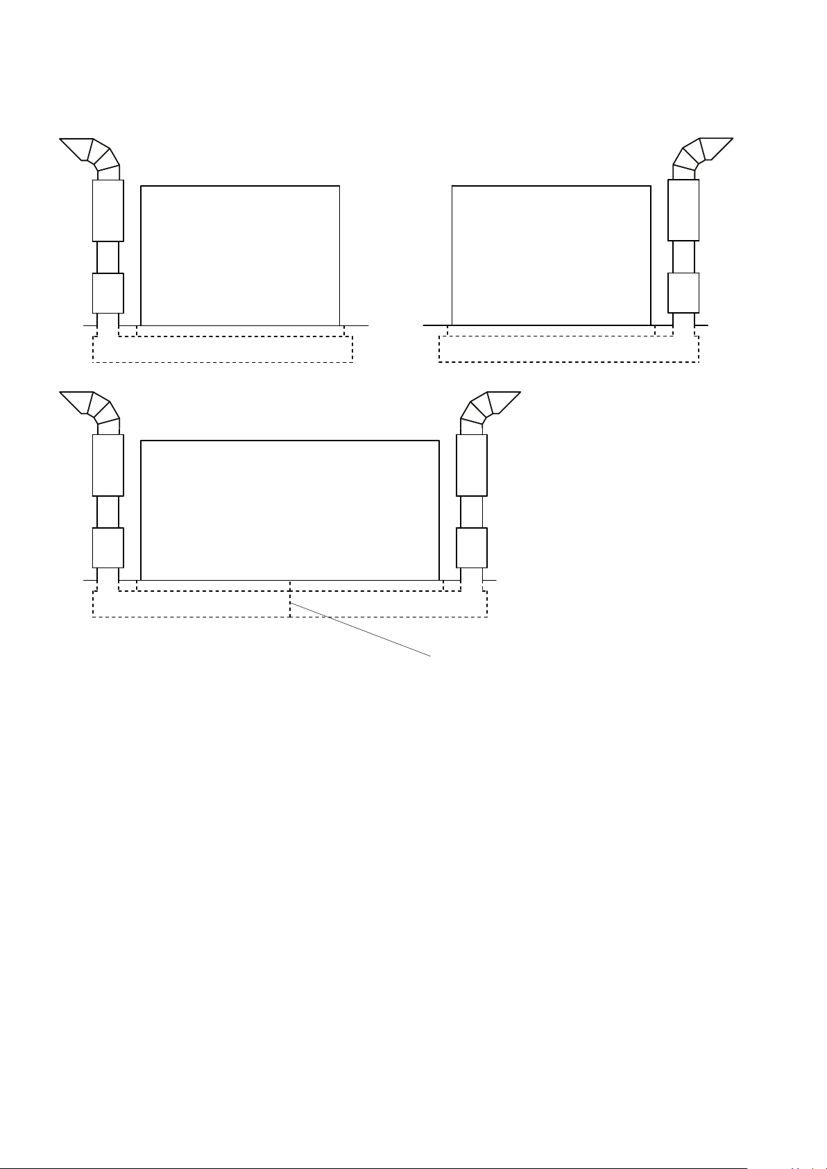
Fig. 2 The positioning of the columns.
Steel wall
4
Page 5
600/750 250
150
Mounting
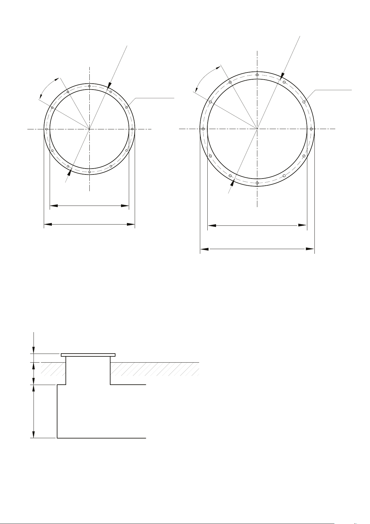
30°
Ø560
UF600
Ø690
30°
12xØ12mm
12xØ12mm
Fig. 3 Flange sizes
500
590
630
720
Fig. 4 Connection box
5
Page 6
A-A
600
250
Inspection hatch
A
UF600
600/750
150
150
B
B
C
Air outlet slot
A
Inspection hatch
C
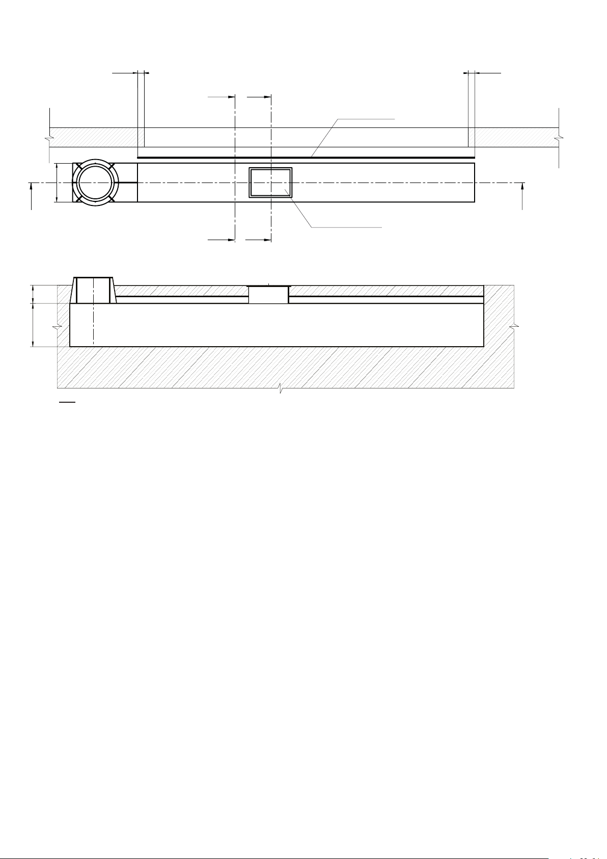
Fig. 5.1 Floor channel
6
Page 7
15°
250
Inspection hatch
250
600/750
650/800
B-B
600/750
250
Air outlet slot
Concrete
25
UF600
25
600/750
C-C
600/750
650/800
50 50
Slot width is determined
by Frico.
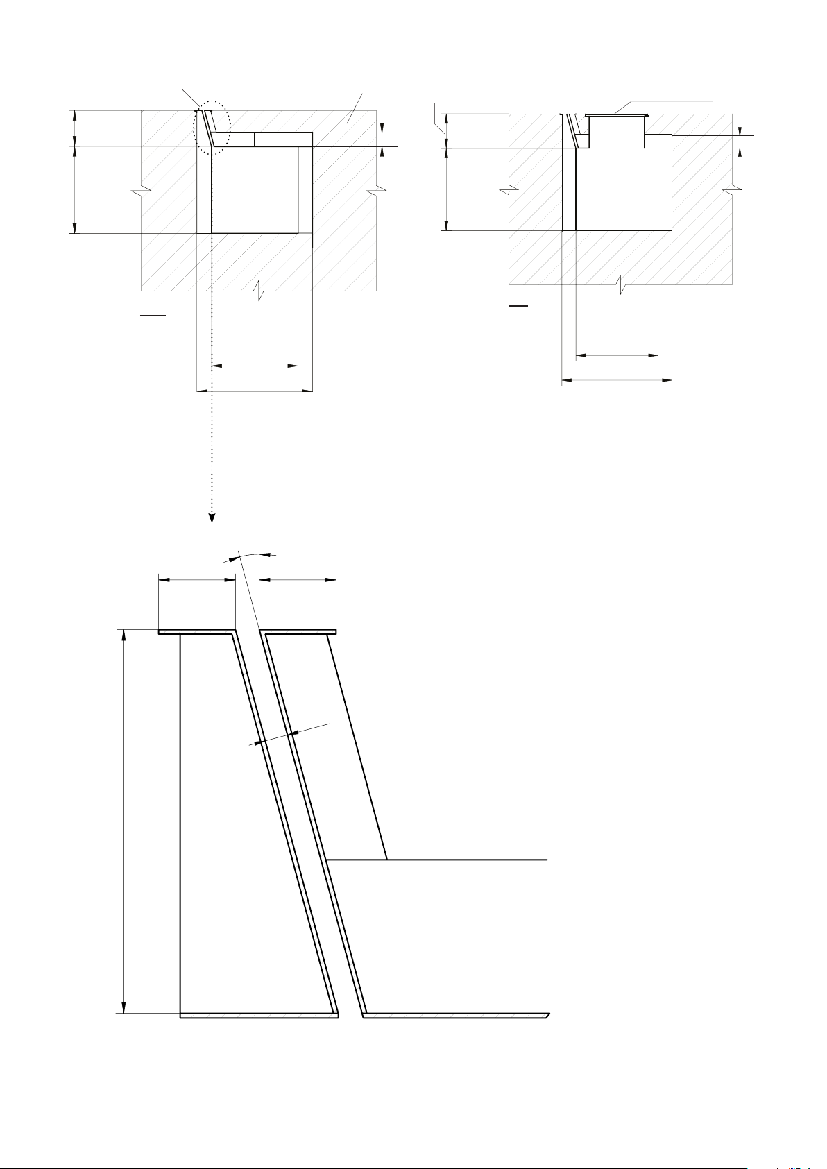
Fig. 5.2 Floor channel - cross sections
7
Page 8
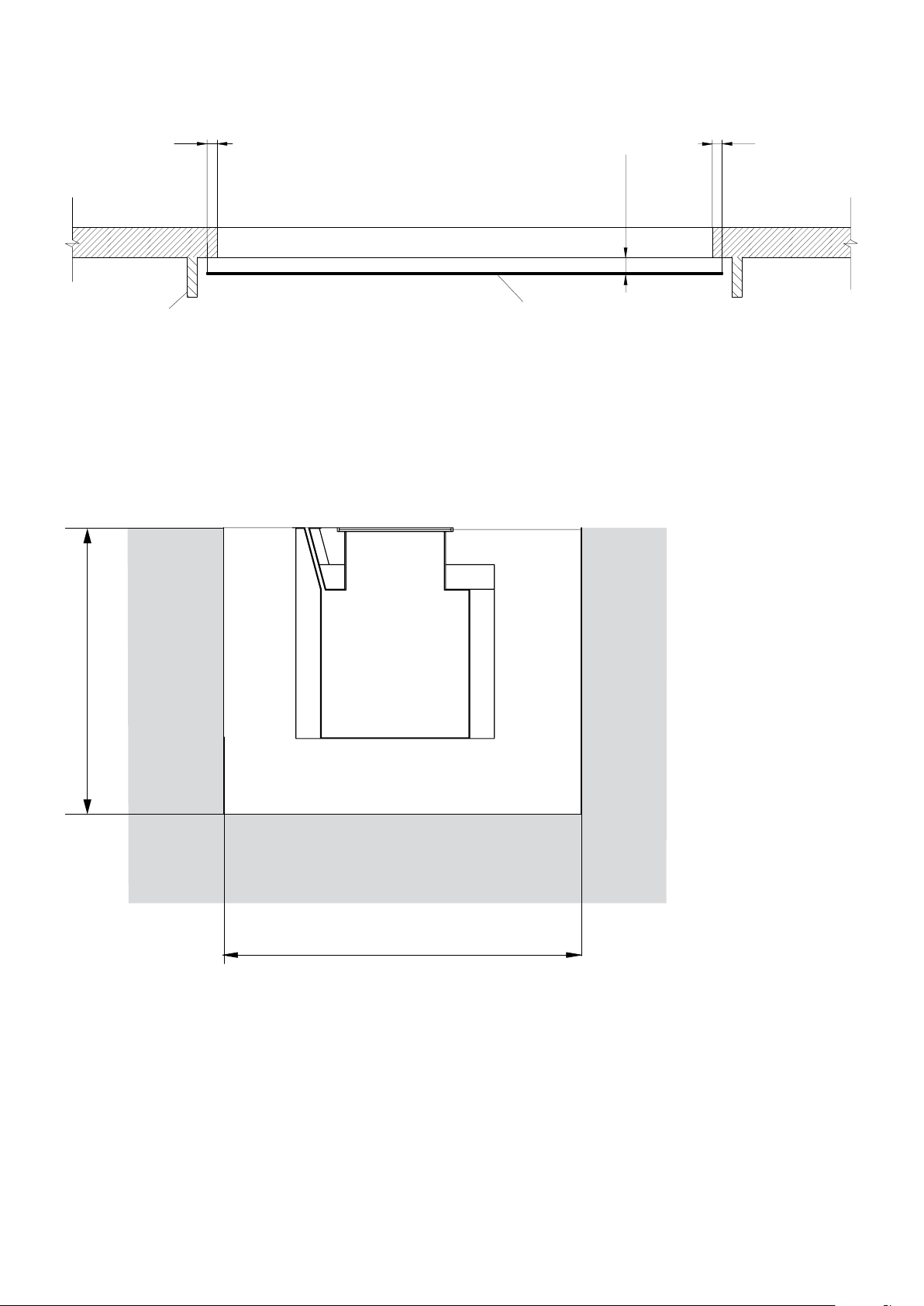
Fig. 6 Air outlet slot
min 150 min 150
x = 250 - 500
Door opening
If x = 300 - 500 => side protection
(If x = 250-300 => no side protection)
Air outlet slot
~1100/1250
UF600
Fig. 7 Pit for embedment
8
~1100/1250
Page 9
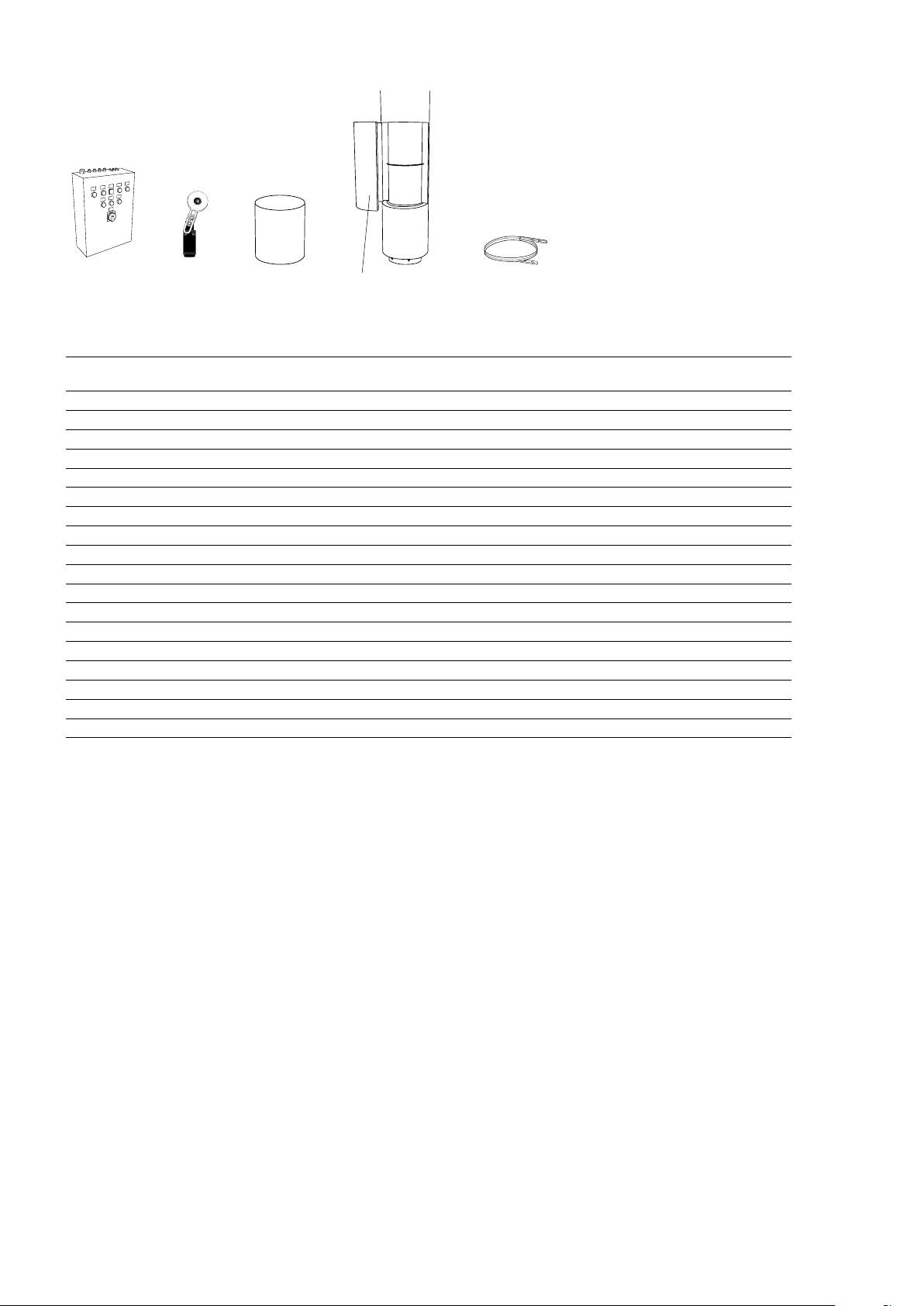
Accessories
UF600
UFC600 AGB304
Type Description HxWxD
UFC601 Control box UF601 600x600x210
UFC602 Control box UF602 600x600x210
UFC603 Control box UF603 600x600x210
UFC604 Control box UF604 800x600x210
UFC605 Control box UF605 800x600x210
AGB304 Position limit switch, IP44
UFEH505 Pillar extension, Ø500 mm, for UF601 L: 500
UFEH510 Pillar extension, Ø500 mm, for UF601 L: 1000
UFEH515 Pillar extension, Ø500 mm, for UF601 L: 1500
UFEH520 Pillar extension, Ø500 mm, for UF601 L: 2000
UFEH605 Pillar extension, Ø630 mm, for UF602-605 L: 500
UFEH610 Pillar extension, Ø630 mm, for UF602-605 L: 1000
UFEH615 Pillar extension, Ø630 mm, for UF602-605 L: 1500
UFEH620 Pillar extension, Ø630 mm, for UF602-605 L: 2000
UFMS750 Motor silencer Ø750 mm, for UF601
UFMS900 Motor silencer Ø900 mm, for UF602-605
UFS750 Securing strip Ø750 mm, for UF601
UFS900 Securing strip Ø900 mm, for UF602-605
UFMSUFEH UFS
[mm]
9
Page 10

Wiring diagrams UF600
Internal wiring diagram
UF600
UF600
∆-connection
U2 V2
W2
U1 V1
W1
L1 L2 L3 PE
M
~
Y ∆
400V~
Y-connection
U2 V2
W2
TK
U1 V1
TK
TK
L1 L2 L3 PE
W1
TK
TK
TK
∆-connection
U2 V2
W2
U1 V1
L1 L2 L3 PE
W1
M
~
Y ∆
400V~
Y-connection
U2 V2
W2
TK
U1 V1
TK
TK
L1 L2 L3 PE
W1
TK
TK
TK
10
Page 11
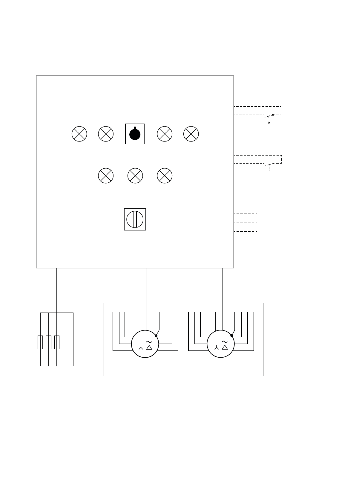
UFC600
(Pot. free contact max 5 A)
UF600
UFC600
Fan 1 Fan 2
On FaultOn
Fault
On/Off/Auto
L3L2L1
Main switch
AGB304
Door contact 230V
External
on/off 230V
Alarm
Indication
Common
L1 L2 L3 NPE
400V3~
UF600
TK TK
W1
V1
3
U1
PE
V2
W2
U2
TK TK
W1
V1
3
U1
PE
V2
W2
U2
11
Page 12

Technical specifications
1 Ambient, no heat - UF600 (IP54)
UF600
Type for indoor
installation
UF601 Indoor UF601 Outdoor 2x4 30 400V3~ 2x7,1 600x600 500 750
UF602 Indoor UF602 Outdoor 2x7,5 35 400V3~ 2x13,7 750x750 630 900
UF603 Indoor UF603 Outdoor 2x11 38 400V3~ 2x22 750x750 630 900
UF604 Indoor UF604 Outdoor 2x15 38 400V3~ 2x28,5 750x750 630 900
UF605 Indoor UF605 Outdoor 2x18,5 40 400V3~ 2x33,7 750x750 630 900
*) Depends on the design of the floor channel.
Type for
outdoor
installation
Output
[kW]
Air
velocity*
[m/s]
Voltage
[V]
Amperage
[A]
Dimensions
floor channel
[mm]
Diameter
fans
[mm]
Diameter
silencer
[mm]
Dimensioning
Door width [m]
3 m 4 m 5 m 6 m 7 m 8 m 10 m
3 m UF601 UF601 UF601 UF601
4 m UF602 UF602 UF602
5 m UF603 UF603 UF604 UF605
6 m UF604 UF605 UF605
Door height [m]
Other door sizes on request. For larger openings, two pillars are required. Please contact Frico.
12
Page 13

GB
Assembly and operating instructions
General Instructions
Read these instructions carefully before
installation and use. Keep this manual for
future reference.
The product may only be used as set out in
the assembly and operating instructions. The
guarantee is only valid if the product is used
in the manner intended and in accordance
with the instructions.
Application area and function
UF600 creates a very effective air barrier
when air at high speed is pushed out through
a narrow channel situated in the floor inside
the door opening. An air barrier directed
upwards from the floor gives the best possible
protection against cold air flowing into the
premises.
UF600 consists of a pillar with inlet hood,
silencers and fans, as well as a floor channel
with its slot at floor level. The pillar is placed
outside (or inside) the door on either side of
the opening. The floor channel is cast in floor.
Its width is adapted to the specific door.
Ambient Temperature limits: -20 °C –55 °C.
Protection class: IP54.
Operation
The air is drawn in through the air inlet at
the top of the unit and blown out through
a narrow air outlet slot in the floor. The
air is distributed at high velocity across
the whole doorway, providing a protective
air shield. The air shield minimises cold
draughts and reduces heat loss through
open doorways. The air outlet slot is angled
outwards 15° to achieve the best protection.
För bästa skydd är det lämpligt att ställa in
olika öppningslägen för dörren för att inte
behöva öppna den mer än nödvändigt. The
efficiency of the air curtain depends on
the air temperature, pressure differences
across the doorway and any wind pressure.
NOTE! Negative pressure in the building
considerably reduces the efficiency of the air
curtain. The ventilation should therefore be
balanced.
Mounting - see Appendix A
The UF600 unit is assembled according to this
manual and bolted together with supplied bolt
kit. The floor channel design choosen is cast
into the floor complete with air outlet slot,
inspection hatch and connection box. The air
outlet slot should extend approximately 150
mm outside the door edges. The UF600 unit
is connected to the connection box with the
flange shown in this manual, see fig. 3.
Pillar extension can be ordered as accessory.
The UF600 unit should be fastened in ceiling
or wall to avoid the risk of tipping if the unit
is hit by a vehicle. UF600 should also be
protected with collision protection.
If the air outlet slot is more than 300 mm
away from the door opening the floor channel
should be prolonged or side protection should
be mounted on both sides of the door to
increase air curtain effect. Standard max load
on floor channel is 7 ton, up to 20 ton for
special orders.
Electrical installation
The air curtain should only be wired by a
competent electrician, and in accordance
with the latest edition of IEE wiring
regulations. The connection is via the
terminal box fitted on the outside of the fan
housing.
See wiring diagrams.
Service, repairs and maintenance
For all service, repair and maintenance first
disconnect the power supply.
The level of cleaning can vary depending on
local conditions. Undertake cleaning at least
twice a year.
Periodically check the following according to
official requirements, however at least once a
year:
• Screw connections, specifically the rotor
fitting.
• Is there dirt in the fan wheel? If so, remove
it.
• Have accumulations formed the rotor? If so,
remove them.
• Functions and settings of the control box
UFC600.
Page 14

GB
• Operating current.
• The floor channel should regularly be
cleaned through the inspection hatch.
NOTE! The power supply must always be
disconnected before disassembling any part
of the unit.
Overheating
All motors are equipped with an integral
thermal safety cut-out. This will operate,
stopping the air curtain should the motor
temperature rise too high. The cut-out
will automatically reset when the motor
temperature has returned to within the
motor’s operating limits.
Control box UFC600 is equipped with motor
protection for each one of the fan motors. If
there is an overload the motor protection will
deploy, stopping the air curtain. The motor
protection must be reset manually. If the
motor protection is deployed, please check
the fuses and if the air inlet is blocked.
Trouble shooting
If the fans are not working or do not blow properly,
check the following:
• Operating power supply to the unit;
check fuses, circuit-breaker, time switch/
thermostat (if any) that starts and stops the
unit.
• Functions and settings of the control box
UFC600.
• That the position limit switch is working.
• That the overheat protection for the motors
has not been deployed.
• That the intake grille/filter is not dirty.
• That the air outlet slot is not blocked.
If the fault cannot be rectified, please contact
a qualified service technician.
Start-up current
The external fusing must be adapted to the
motor start-up current.
Safety
- Do not cover surfaces of the air curtain or
obstruct air inlet, as this can cause excessive
temperatures that can be hazardous and may
cause fan motor malfunction.
- Do not block the air outlet slot.
- The air velocity will be too high for people
to go through the air flow. People should not
enter the opening without protection from a
vehicle etc.
Control options
Control box UFC is available as accessory.
Accessories
UFC, control box
Y/D-start with time delay between the motors.
Possibility to use with door switch or position
limit switch or external on/off. Integrated
motor protection for each fan. Alarm and
running indication.
AGB304, position limit switch
Starts the air curtain when the door is
opened and stops it when the door is closed.
Alternating contact 4 A, 230 V~. IP44.
UFEH, pillar extension
For indoor mounting the air intake should
be above the door opening, therefore an
extension of the pillar is sometimes necessary.
This is placed between the inlet hood and the
upper silencer.
UFMS, motor silencer
Additional motor silencer which gives a lower
sound level and a uniform tower.
Drainage
If there is a risk of large amounts of water
running into the floor channel, a drainage
pipe should be connected to the existing 1”
connection (internal thread).
Do not connect the drainage to the sewage
(risk of blowing out water lock).
UFS, securing strip
The securing strip is mounted round the
upper silencer and fixed to the outside wall to
avoid the risk of tipping.
Page 15

GB
Explanation of pages 1-12
Fig. 1 Dimensions
1. Intake with bird protection grille (or inlet nozzle
for indoor installation)
2. Inlet side silencer
L = 1 480 mm
3. Axial fan 400V
4. Axial fan 400V
5. Motor silencer
6. Silencer pressure side
L = 1 000 mm
7. Floor channel
Installation alternatives
Fig. 2 The positioning of the columns
The fan pillar can be positioned on either side
of the door. For large doors, two fan pillars
are often required. They should be positioned
one on each side. When two units are placed
on each side of the doorway, the floor channel
has to be divided by a steel wall in the middle
to prevent the fans from working against each
other.
Mounting
Fig. 3 Flange sizes
The pillar is connected to the connection
box with flange according to the picture. The
UF600 flange comes with Ø12 mm holes.
Fig. 4 Connection box
The connection box is where the pillar is
connected to the floor channel. Please contact
Frico for more information.
Fig. 5, 5.1 Floor channel, - cross sections
The floor channel box is a steel construction
that is cast into the concrete floor. The outlet
opening is at floor level, as close to the floor
opening as possible. The length of the box and
the angle and column width is determined at
the project planning stage.
The channel can be made in one piece or
delivered in sections which are then welded
together on location and include air outlet
slot, connection box and inspection hatch.
Measurements are suggestions. The air outlet
slot should extend minimum 150 mm outside
the door edges on each side. Please contact
Frico for more information.
Fig. 6 Air curtain slot
To compensate for the inward-directed
pressure force, the air curtain slot is directed
at an outward angle of about 15°. The air
curtain slot should be at least 300 mm wider
than the door opening. If the air outlet slot
is more than 300 mm away from the door
opening the floor channel should be prolonged
or side protection should be mounted on both
sides of the door to increase air curtain effect.
Fig. 7 Pit for embedment
Page 16

Appendix A
UF600
51
Page 17

1
UF600
2
52
Page 18

3
4
UF600
5
53
Page 19

6
UF600
7
8
54
Page 20

9
UF600
10
11
55
Page 21

12
UF600
13
56
Page 22

14
UF600
15
16
57
Page 23

17
UF600
18
19
58
Page 24

20
21
UF600
59
Page 25

22
UF600
23
60
Page 26

24
UF600
61
Page 27

Page 28

Page 29

Main offi ce
Frico AB Tel: +46 31 336 86 00
Box 102
SE-433 22 Partille mailbox@frico.se
Sweden www.frico.se
For latest updated information and information
about your local contact: www.frico.se
20170914 HH/LE
 Loading...