

Frico Thermozone PA3500, Thermozone PA4200 Original Instructions Manual
Thermozone PA3500/4200
.... 27
SE
.... 46
PL
.... 34
FR
.... 26
NO
.... 30
FI
.... 42
RU
.... 31
GB
.... 38
DE
.... 54
NL
.... 50
IT
.... 58
ES
.... 62
HU
Original instructions
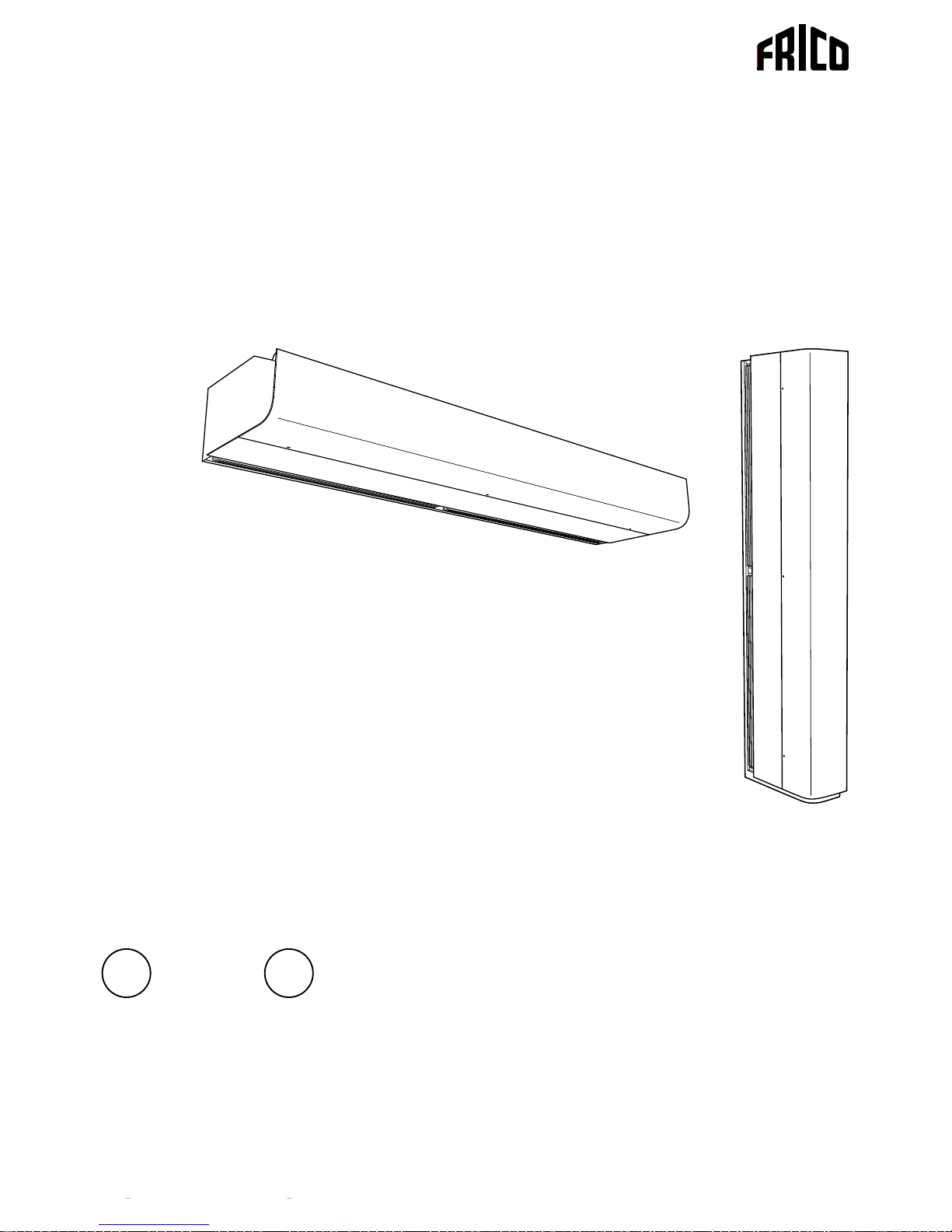
PA3500/4200
2
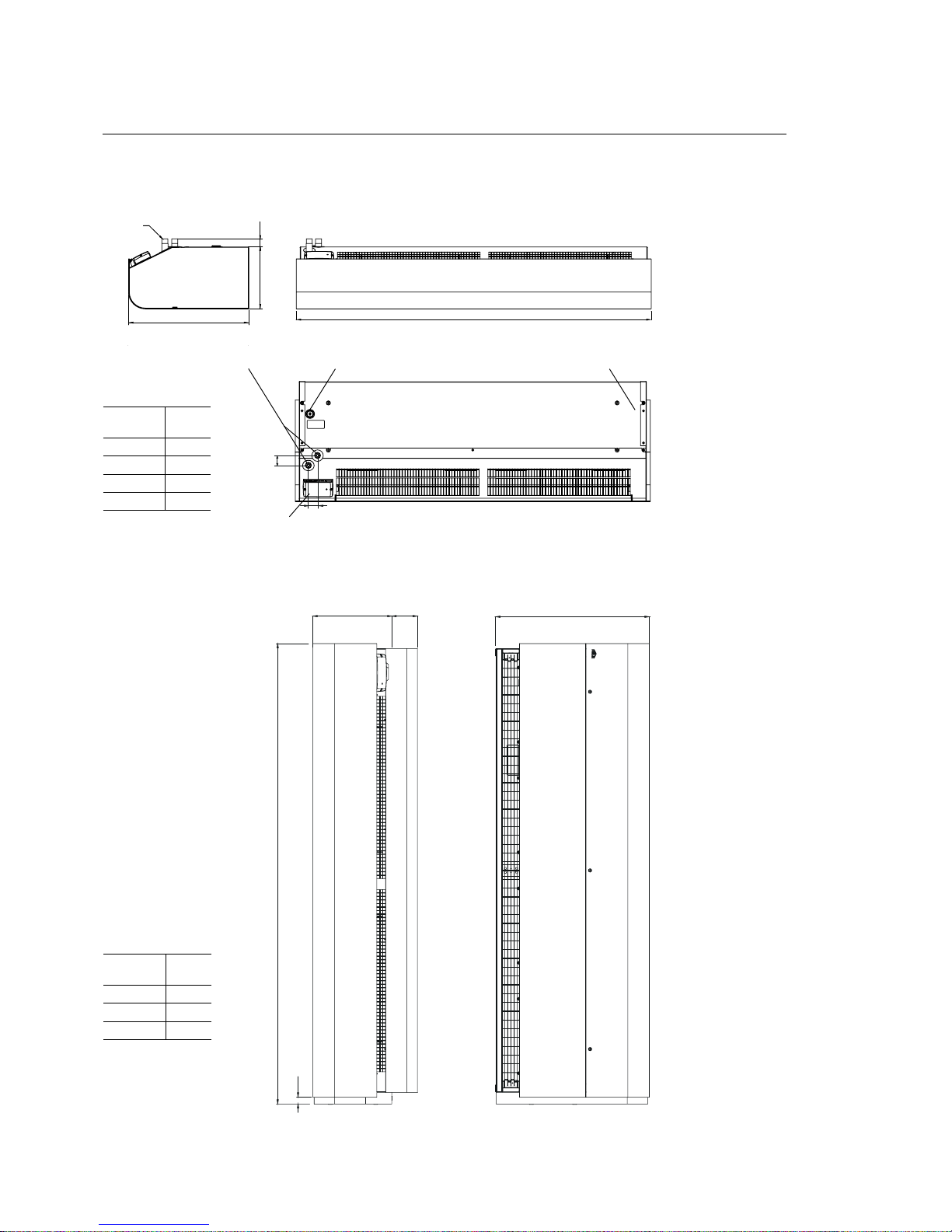
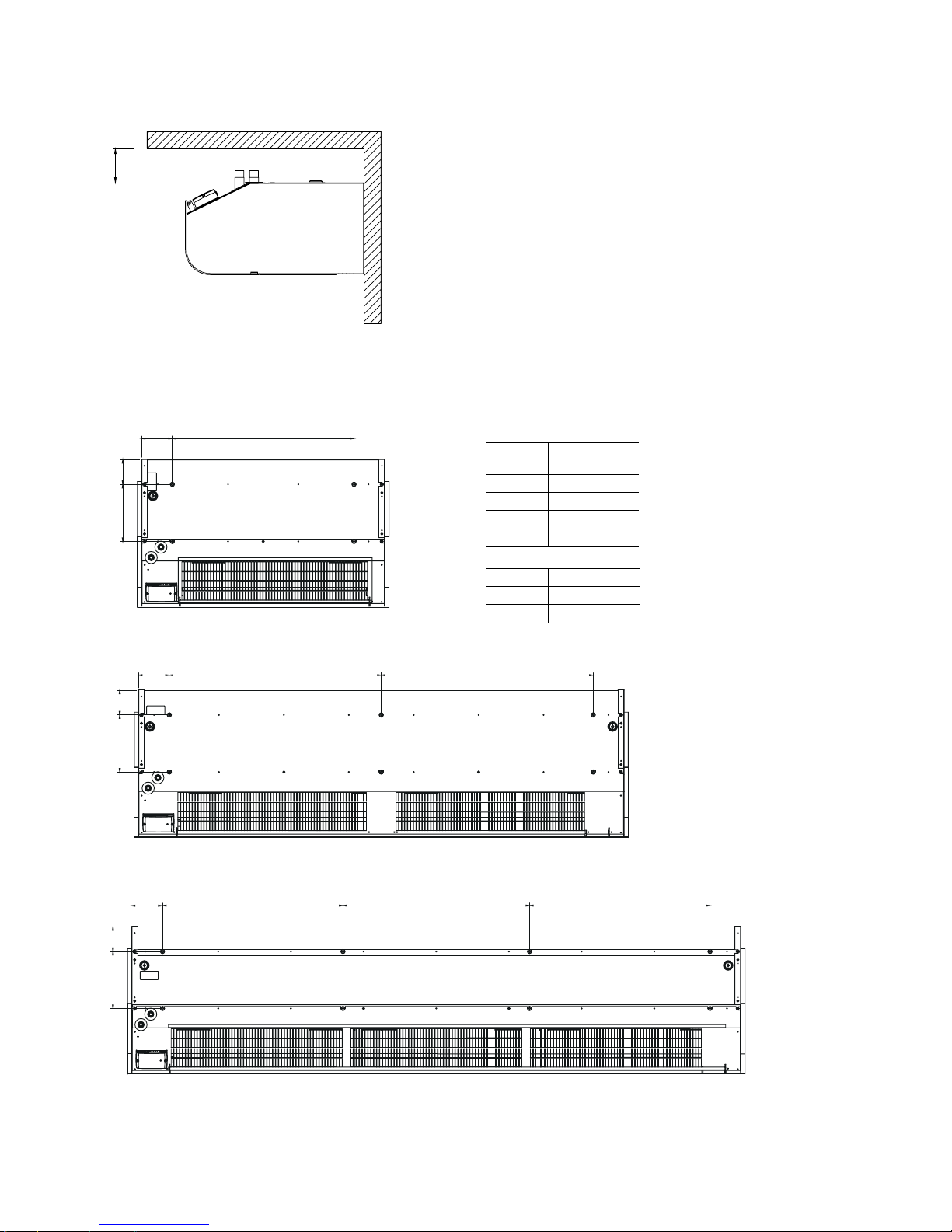
Dimensions
Water connection Electrical connection
DN20 (3/4"),
outside thread
SIRe
PA 2 m; 2,5 m
Electrical connection
The unit can be
reversed and placed
on either side of the
door. Connections
and PC Board SIRe
are positioned near
floor level when the
air curtain is placed
to the left of the door
and at the top when it
is placed to the right
(seen from the inside).
All models
Vertical mounting
Horizontal mounting
with Vertical kit and Design kit for vertical mounting
with Vertical kit
and Design kit for
vertical mounting
*)
525
L
270 36
43
40
L
525
87270
23
525
L
270 36
L
[mm]
PA3510 1039
PA3515 1549
PA3520 2039
PA3525 2549
L
[mm]
PA3515* 1549
PA3520* 2039
PA3525* 2549
PA3500
PA3500/4200
3
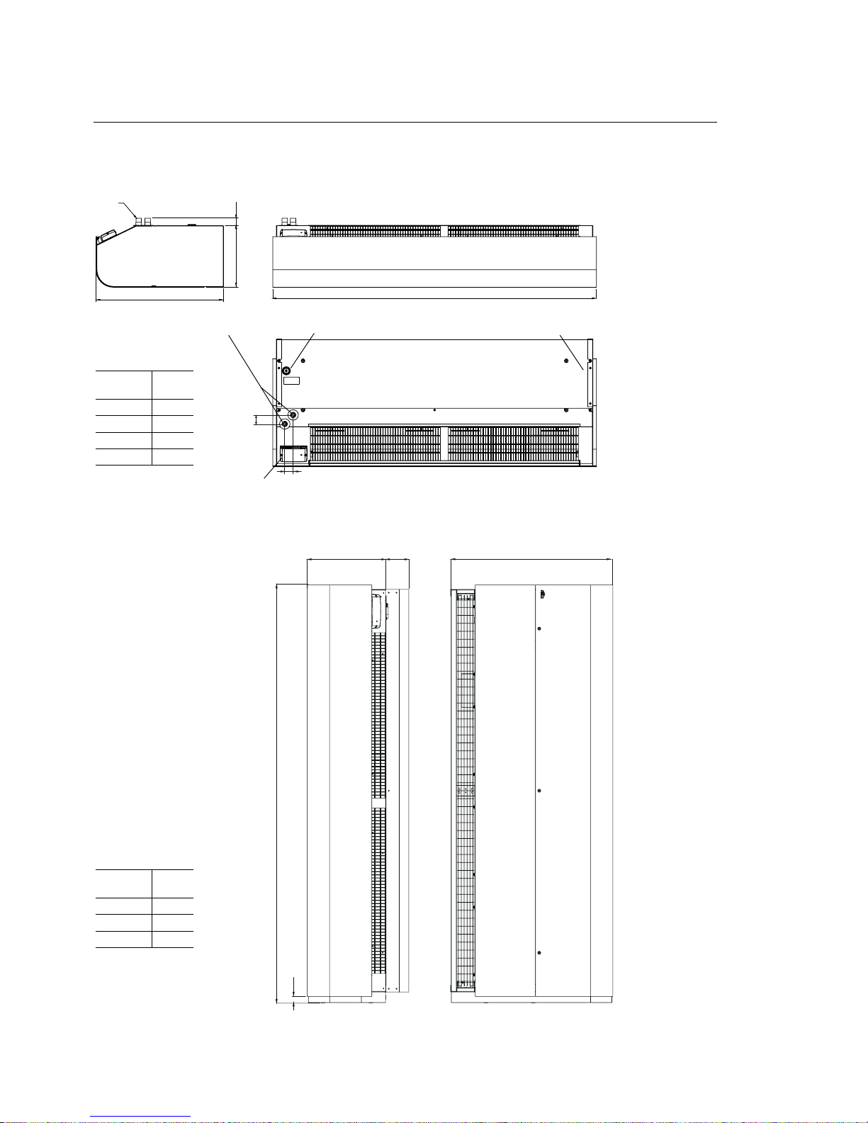
Dimensions
Water connection Electrical connection
DN20 (3/4"),
outside thread
PA 2 m; 2,5 m
Electrical connection
The unit can be
reversed and placed
on either side of the
door. Connections
and PC Board SIRe
are positioned near
floor level when the
air curtain is placed
to the left of the door
and at the top when it
is placed to the right
(seen from the inside).
All models
Vertical mounting
Horizontal mounting
with Vertical kit and Design kit for vertical mounting
611
L
295 36
43
40
611
L
23
295 87
L
[mm]
PA4510 1039
PA4515 1549
PA4520 2039
PA4525 2549
L
[mm]
PA4515* 1549
PA4520* 2039
PA4525* 2549
611
L
295 36
PA4200
with Vertical kit
and Design kit for
vertical mounting
*)
SIRe
PA3500/4200
4
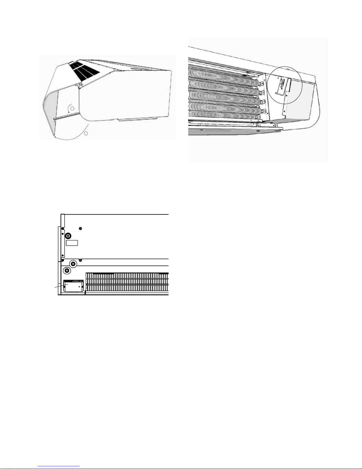
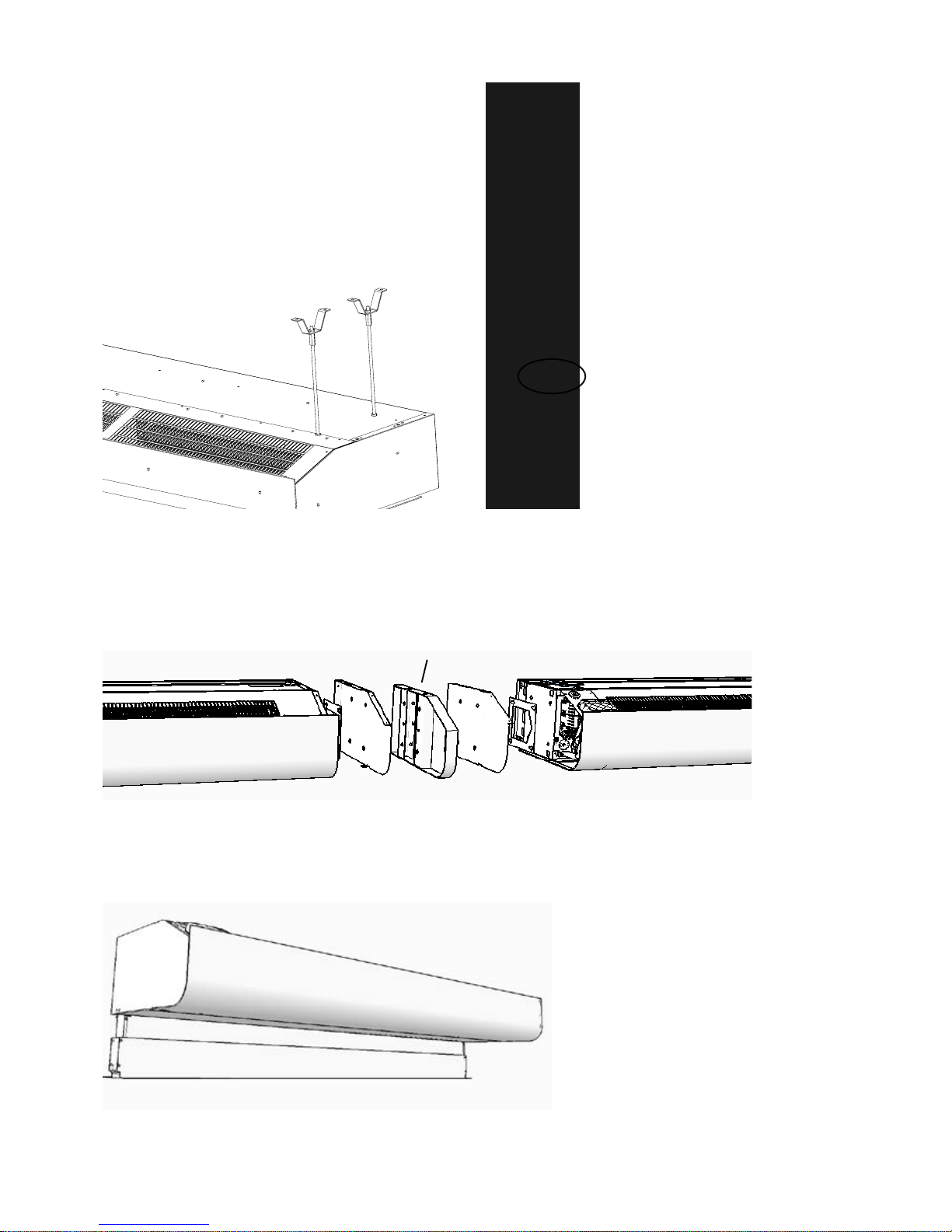
Open the unit
2
1
Fig. 1A: Open the unit by raising the front panel. The front
is blocked in open position with the front hatch hook
Fig. 2: Control card SIRe is integrated in the air curtain at delivery.
SIRe
Integrated control system
Fig. 1B: When the front has been removed it it important
to be sure it is firmly seated in the front locks again.
PA3500/4200
5
100
Fig. 3: Minimum distance.
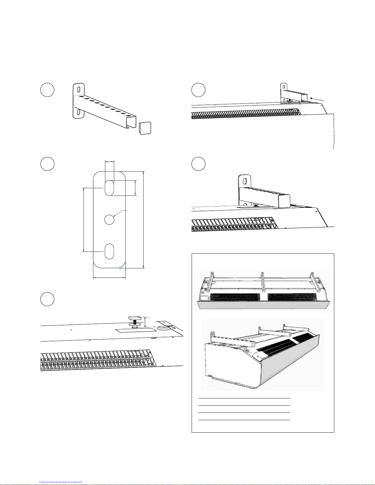
Mounting
A
B
A
127
L
B
127
875875
AB
127
770745 745
Fig. 4: M8-holes for mounting.
L
[mm]
PA3510 750
PA4210 750
PA3515 1260
PA4215 1260
A B
PA3500 205 92
PA4200 235 102
PA3500/4200
6
Fig. 5: Mounting with wall brackets (PA34WB).
Horizontal mounting
Horizontal mounting - wall bracket PA34WB
20 mm
A
B
C
D
PA34WB15 2 pcs
PA34WB20 3 pcs
PA34WB30 4 pcs
79
19
120
11
40
ø12
E
PA3500/4200
7
Fig. 6: Mounting with threaded bars (PA34TR) and ceiling
brackets (PA34CB). Supplemented with vibration dampers
(PA34VD) for reduced vibration.
See separate manual for PA34TR.
Fig. 7: Mounting with wire suspension kit (PA34WS), used
together with ceiling brackets (PA34CB).
See separate manual for PA34WS.
Wire lock
Horizontal mounting
Fig. 8: Joining kit PA3JK to join horizonal units together.
See separate manual for PA34JK - joining kit for horizontal
units.
Joint bracket
Fig. 9: Outlet extension PA3XT / PA4XT with telecopic
funktion used for recessed mounting in false ceilings. See
separate manual for PA3XT / PA4XT.
PA3500/4200
8
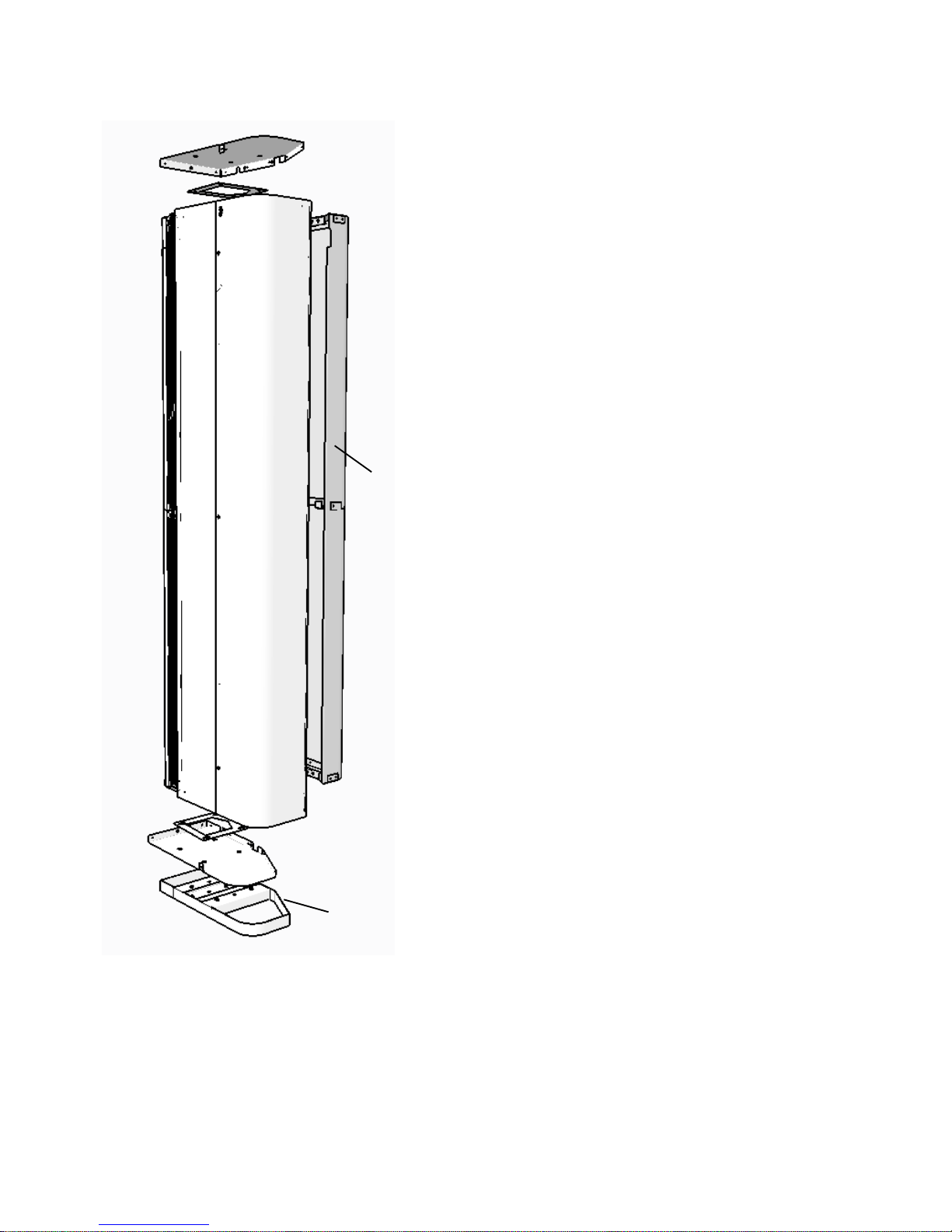
Mounting - vertical
Fig. 10: Vertical kit PA3JK to adapt horizonal unit for
vertical installation. Used together with design kit for
vertical installation for a neater installation.
See separate manual for PA3JK - Vertical installation.
Floor edging
Design kit for
vertical mounting
Accessories
Type Description Number included Length
PA34WB15 Wall brackets for PA3510/3515/4210/4215 2 pcs 400 mm Fig. 4
PA34WB20 Wall brackets for PA3520/4220 3 pcs 400 mm Fig. 4
PA34WB30 Wall brackets for PA3525/4225 4 pcs 400 mm Fig. 4
PA34CB15 Ceiling brackets for PA3510/3515/4210/4215 4 pcs Fig. 5/6
PA34CB20 Ceiling brackets for PA3520/4220 6 pcs Fig. 5/6
PA34CB30 Ceiling brackets for PA3525/4225 8 pcs Fig. 5/6
PA34WS15 Wire suspension kit for PA3510/3515/4210/4215 4 pcs 3 m Fig. 6
PA34WS20 Wire suspension kit for PA3520/4220 6 pcs 3 m Fig. 6
PA34WS30 Wire suspension kit for PA3525/4225 8 pcs 3 m Fig. 6
PA34TR15 Threaded bars for PA3510/3515/4210/4215 4 pcs 1 m Fig. 5
PA34TR20 Threaded bars for PA3520/4220 6 pcs 1 m Fig. 5
PA34TR30 Threaded bars for PA3525/4225 8 pcs 1 m Fig. 5
PA34VD15 Vibration dampers for PA3510/3515/4210/4215 4 pcs
PA34VD20 Vibration dampers for PA3520/4220 6 pcs
PA34VD30 Vibration dampers for PA3525/4225 8 pcs
PA3JK Joining kit for PA3500 Fig. 7
PA4JK Joining kit for PA4200 Fig. 7
PA34EF10 External intake filter for PA3510/4210
PA34EF15 External intake filter for PA3515/4215
PA34EF20 External intake filter for PA3520/4220
PA34EF25 External intake filter for PA3525/4225
FHDN20
Flexible hoses DN20, inside thread, 90° bend,
water temp. up to 90° C
1 pair 350 mm
For horizontally mounted units
Mounting and installation
See manual for FHDN20.
See manual for PA34EF.
PA3500/4200
9
Type Description HxDxW
[mm]
PA3DW10 Design kit for wall mounting PA3510 87x382x1006
PA3DW15 Design kit for wall mounting PA3515 87x382x1516
PA3DW20 Design kit for wall mounting PA3520 87x382x2006
PA3DW25 Design kit for wall mounting PA3525 87x382x2516
PA4DW10 Design kit for wall mounting PA4210 87x424x1006
PA4DW15 Design kit for wall mounting PA4215 87x424x1516
PA4DW20 Design kit for wall mounting PA4220 87x424x2006
PA4DW25 Design kit for wall mounting PA2425 87x424x2516
Design kit for wall mounting
Accessories
For horizontally mounted units
Start parts
Type
Description Number
included
PA3DCN15S Start part for PA3510/3515 2 pcs
PA3DCN20S Start part for PA3520 3 pcs
PA3DCN30S Start part for PA3525 4 pcs
Intermediate parts
Type
Description Number
included
PA3DC15S
Intermediate part 300 mm for
PA3510/3515
2 pcs
PA3DC20S
Intermediate part 300 mm for
PA3520
3 pcs
PA3DC30S
Intermediate part 300 mm for
PA3525
4 pcs
PA3DC15M
Intermediate part 500 mm for
PA3510/3515
2 pcs
PA3DC20M
Intermediate part 500 mm for
PA3520
3 pcs
PA3DC30M
Intermediate part 500 mm for
PA3525
4 pcs
PA3DC15L
Intermediate part 700 mm for
PA3510/3515
2 pcs
PA3DC20L
Intermediate part 700 mm for
PA3520
3 pcs
PA3DC30L
Intermediate part 700 mm for
PA3525
4 pcs
Telescopic parts
Type
Description Number
included
PA3DC15T
Telescopic part for
PA3510/3515
2 pcs
PA3DC20T Telescopic part for PA3520 3 pcs
PA3DC30T Telescopic part for PA3525 4 pcs
See manual for PA3DW/PA4DW.
Design kit for ceiling mounting PA3500
Intermediate
part
Telescopic
part
See manual for PA3DC.
Start part
PA3500/4200
10

Type Description
PA3XT10
Outlet extension for PA3510, 130-200 mm Fig. 8
PA3XT15
Outlet extension for PA3515, 130-200 mm Fig. 8
PA3XT20
Outlet extension for PA3520, 130-200 mm Fig. 8
PA3XT25
Outlet extension for PA3525, 130-200 mm Fig. 8
PA4XT10
Outlet extension for PA4210, 130-200 mm Fig. 8
PA4XT15
Outlet extension for PA4215, 130-200 mm Fig. 8
PA4XT20
Outlet extension for PA4220, 130-200 mm Fig. 8
PA4XT25
Outlet extension for PA4225, 130-200 mm Fig. 8
For recessed mounting in false ceiling
Intermediate parts
Type
Description Number
included
PA4DC15S
Intermediate part 300 mm for
PA4210/4215
2 pcs
PA4DC20S
Intermediate part 300 mm for
PA4220
3 pcs
PA4DC30S
Intermediate part 300 mm for
PA4225
4 pcs
PA4DC15M
Intermediate part 500 mm for
PA4210/4215
2 pcs
PA4DC20M
Intermediate part 500 mm for
PA4220
3 pcs
PA4DC30M
Intermediate part 500 mm for
PA4225
4 pcs
PA4DC15L
Intermediate part 700 mm for
PA4210/4215
2 pcs
PA4DC20L
Intermediate part 700 mm for
PA4220
3 pcs
PA4DC30L
Intermediate part 700 mm for
PA4225
4 pcs
Telescopic parts
Type
Description Number
included
PA4DC15T
Telescopic part for
PA4210/4215
2 pcs
PA4DC20T Telescopic part for PA4220 3 pcs
PA4DC30T Telescopic part for PA4225 4 pcs
Design kit for ceiling mounting PA4200
Intermediate
part
Telescopic
part
See manual for PA4DC.
Accessories
For horizontally mounted units
PA3500/4200
11
 Loading...