

Page 1
Thermozone AC 300
SE
... 12
... 8
NO
FR
... 28
... 24
PL
... 40
... 44
IT
FI
... 20
...16
GB
NL
... 36
... 32
RU
ES
... 48
DE
Page 2
Thermozone AC 300Thermozone AC 300
2
1000 / 1665
335
Ø 11
Ø 20
490
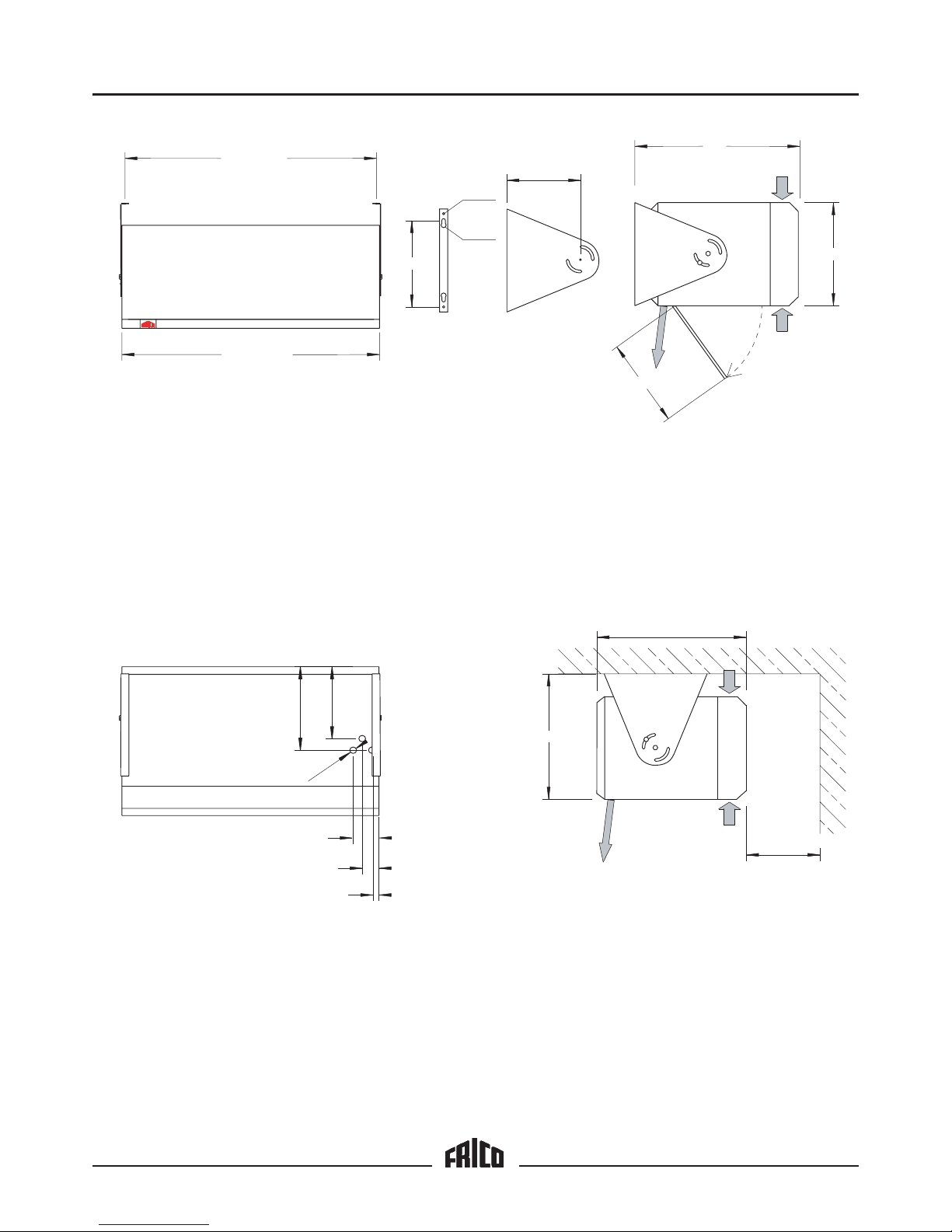
Fig. 1
975 / 1640
640
400
min 300
580
Fig. 3
280
325
24
65
100
3x Ø29
287
Fig.2
360
Thermozone AC 300
Page 3
Thermozone AC 300
3
AC 300
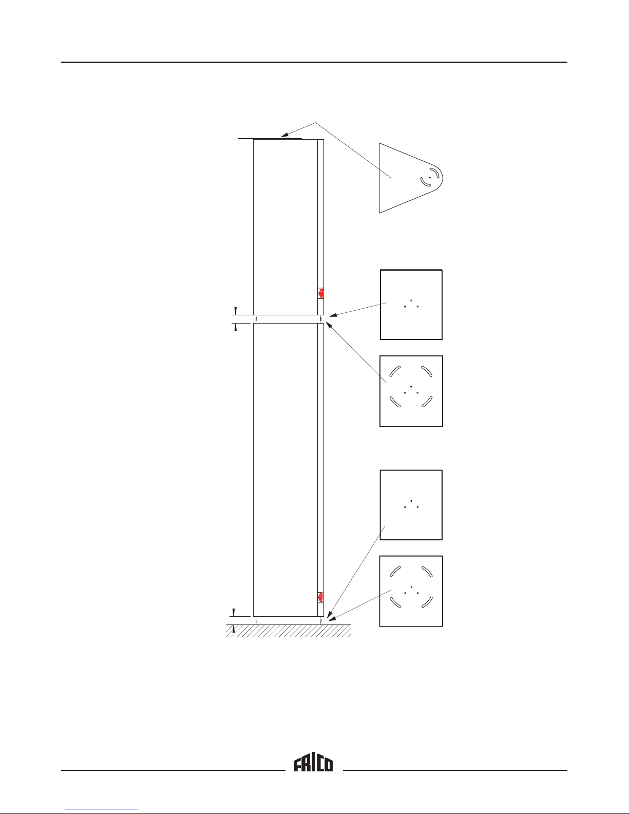
Fig. 4
45
AVMP300
AVMP300
45
AC 300
Thermozone
Thermozone
Page 4
Thermozone AC 300
4
7531
268
ACR 304
0
1357
1
2
3
4
NL
PTC
123456NL
NL
7 8 9
230V~
AC 301, -302 230V~
KS101.1
~
N
2221 AG
AC 301, -302
1234NL
230V~
KS102.2
AGB 304
~
N
2221 AG
AC 301, -302
1234NL
230V~
KS103.2
~
M
˚C
~
M
˚C
~
M
˚C
Page 5

Thermozone AC 300
AC 301, -302
123456NL 9
230V~
AC 301, -302
4569
AC 301, -302
4569
1234
AGB 304
456783
ACR 3042
2
1
KS104.1
5
Page 6

Thermozone AC 300
7531
2468
ACR 304
0
1357
1
2
3
4
5
1
2
6
EV 300
62
13121110
321
400V 3~
LLL
K1
K2
230 V 3~
14
400V 3~ / 230V 3~
AC 308, -312 400V 3(N)~ / 230V 3~
~
M
NL
PTC
123456NL
NL
7 8 9
230V~
1
2
3
2
3
1
Hi
Lo
KRT 2800
KS106.1
~
M
~
M
˚C
˚C ˚C
Diff Hi - Lo 1 - 4 ˚C
˚C
˚C
˚C
6
Page 7

Thermozone AC 300
AC 308, -312
123456NL 7
230V~
AC 308, -312
456
AC 308, -312
456
321
LLL
400V 3~ / 230V 3~
5
1
2
6
EV 300
121314
10
321
LLL
400V 3~ / 230V 3~
121314
10
321
LLL
400V 3~ / 230V 3~
121314
10
1
2
3
2
3
1
Lo
KRT 2800
AGB 304
34 35 36 37 3833
ACR 3042
32
1234
31
KS107.1
Diff Hi - Lo 1 - 4 ˚C
˚C
7
Page 8

Thermozone AC 300
Application area
The Thermozone AC 300 air curtains are
intended for stationary installation above or
at the side of entrance and smaller doors with
a height between 2.5 and 3.5 metres.
The Thermozone AC 300 is supplied with
or without heating elements. Electric heat
can be added to units without heat
afterwards.
The efficiency of the air curtains is
dependent on the difference of air pressure
and temperature (between the rooms that are
separeated by the air curtain) and pressure
caused by wind.
The protection class of AC 300 is IP 24,
drip-proof design.
Operation
The air is drawn in from the upper and under
side of the unit and is blown out at high
velocity across the doorway, providing a
protective air shield. The air shield
minimizes heat and cold air leakage.
When mounted on supplied brackets, the
units can be directed with regard to the size
of load on the door in question. The more
load caused by negativ pressure, temperature
differences and wind, the more should the air
stream be directed outwards.
The air flow is adjusted with a selector
(ACR304 eller ACR3042) to provide maximum protection to the opening.
Units with electric heat can be regulated
with the output selector EV300 in 3 stages
(0 - 1/2 - 1/1) and with a 2-stage thermostat,
KRT 2800.
NOTE! Air pressure imbalance between
rooms separated by air curtains, considerably
reduces the efficiency of the air curtain. The
ventilation should therefore be balanced!
Mounting
a) Above the doorway
• The unit is usually mounted inside the
doorway as close to the opening as
possible with the nozzle closest to the
opening.
• When used above interior freezer doors,
the unit should be mounted on the warm
side.
• To minimize air leakage between the units,
they should be mounted close to each
other. To reach the wall mounting
screws, a min gap of 50 mm between the
units is required.
• Attach the two (2) wall mounting brackets
securely to the wall or suitable structure.
Attach the air curtain to the brackets
(Fig.1). The units are secured with M10screws in the centre hole of each bracket
and in one of the notches, thus allowing
the whole unit to be turned and the angle
of the air stream to be adjusted.
• Observe the minimum distances given in
fig.3 and also that the units may not be
mounted directly below a power outlet.
b) Standing at the side of the doorway
• When space above the doorway is
limited, the units can be mounted standing
beside the opening, thus creating a sideblowing air stream (fig.4). Mounting plates
AVMP300 are mounted between units and
between the lowest unit and the floor.
• The units are mounted vertically inside the
doorway as close to the edge of the
opening as possible with the nozzle
closest to the opening.
• The mounting plate consists of two parts.
The outer one is secured in the floor (or at
the top of the lower unit) with the supplied
screws. The units are secured with M10screws in the centre hole of each bracket
and in one of the notches, thus allowing
the whole unit to be turned and the angle
of the air stream to be adjusted. The inner
part is mounted on the under side of unit
that is standing on the floor. The plate is
secured with 3 M10-screws in the
prepared screw holes.
• Lift the unit on to the plate and screw the
plates together. Maximum building height
for vertical units is 3.5 metres.
• At the end of the uppermost unit, one of
the supplied mounting consoles (or other
suitable strut) is mounted and then
attached to the wall in order to secure the
top of the tower.
• We recommend that the collision
protection AXP300 is mounted to prevent
the units from being hit by trucks and
similar.
• Mount the air flow selector ACR304 or
ACR3042 withing easy reach for
controlling the air curtains.
• To control units with electric heat, the
output selector EV300 is mounted in
conjunction with the speed selector and a
thermostat (for ex. KRT2800), in such a
place that changes of the temperature
close to the opening, can be quickly
detected.
Installation and Operating Instructions
GB
20
Page 9

Thermozone AC 300
• When mounting vertically, draught can
occur due to rotating air. The mounting of
a narrow wall at the side of the opening
(the side where no units are mounted),
can decrease the rotation.
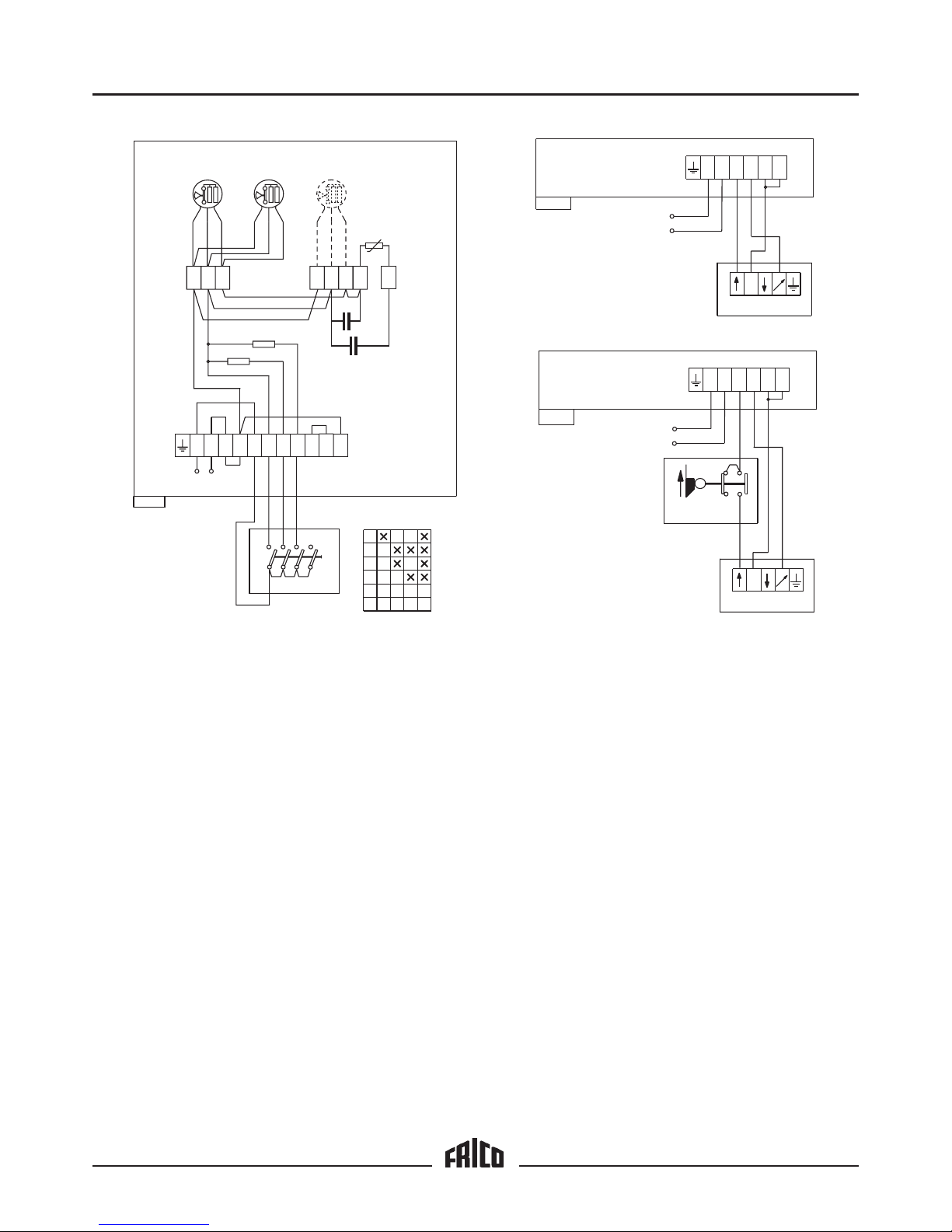
Electrical installation
The electrical installation should be carried
out by a qualified electrician in conformity
with prevailing regulations. The appliance
should be preceded by a triple pole switch
with at least 3 mm breaking gap.
Different alternatives for air flow
regulation are possible, see wiring diagram
pages 4-7.
The hatch on the underside of the unit is
opened by turning the locking pins 1/4 of a
lap. The connection should be made with a
cable type S05VV-U, A05VV-R or similar.
On the upper side of the unit there are
knock-outs, 2 pcs ø 37 mm and 3 pcs ø 29
mm. The cable-glands used must guarantee
the protection class requirements!
Type Power Voltage Min. area
kW V mm
2
All control 230V 1,5
AC 308 8 230V 3~ 4
AC 308 8 400V 3~ 2,5
AC 312 12 230V 3~ 10
AC 312 12 400V 3~ 4
For the units with electrical heating, the
power and voltage should be supplied in
different connection areas (see wiring
diagram).
In the distribution board it is to be
indicated that ”the air curtains can be
supplied from more than one connection”.
Adjusting the unit and the air stream
Direction and speed of the air stream should
be adjusted with regard to the load on the
door. Pressure forces the air stream to bend
towards the interior of the room (when the
room is heated and the outside is cold). To
withstand the load, the air stream should be
directed outwards. An angel up to 15° can be
recommended. The more load caused by
negativ pressure, temperature differences
and wind, the more should the air stream be
directed outwards.
A baffle on each side of the doorway will
improve the efficiency of the air curtains.
When used above freezer or cooler doors,
the units should be mounted on the warm
side with the air stream directed 0-10°
towards the warm side.
Basic air flow settings
The air flow is set with the air flow selector
so that the speed of the air is 3-4 m/s 1 m
above the floor. The direction of the air
stream and the air speed may need to be
adjusted more exactly depending on the
load on the door.
Trouble shooting
If the fans stand still, check the following:
a) Power supply; check fuses, circuit-breaker,
time switch (if any) that starts and stops
the unit.
b) That the air flow selector is correctly set.
c) That the position limit switch is working
(if any).
If the error cannot be fixed, please contact
qualified service technician.
If there is no heat, check the following:
a) Power supply to electric heater; check
fuses and circuit-breaker (if any).
b) Thermostat settings and actual
temperature.
c) That the output selector (if any) is set
correctly.
d) That the overheat protection has not
been released. If so, please check
description on next page.
Overheating
(applies to units with electric heat)
The Thermozone is equipped with an
overheat protector. If it is released due to
overheating, reset as follows:
a) Disconnect the electricity with the fully
isolated switch.
b) Investigate the matter and repair the
fault.
c) Reset is performed as follows:
• Dismount the service hatch on the
underside of the unit.
• Locate the red buttons.
• Press the buttons until a click is heard
(you do not need to press them
simultaneously).
d) Connect the Thermozone again.
If the error cannot be fixed, please contact
qualified service technician.
GB
21
Page 10

Thermozone AC 300
Security
• Ensure that the area around the intake and
exhaust grille is kept free from material
which could prevent the air to flow through
the unit!
• During operation the surfaces of the unit
are hot!
• The unit must not be covered fully or
partially with clothes, or similar materials,
as overheating can result in a fire risk!
Maintenance
NOTE! Disconnect electricity prior to cleaning
or inspection (units with electric heat can be
supplied from more than one connection).
The fan motors and the other components
require no maintenance other than cleaning
when necessary, however at least once year.
Grille, impeller and elements are vacuum
cleaned or dried clean with a damp cloth.
Open the inspection hatch to reach elements
and impellers.
Safety cut-out
(applies to units with electric heat)
If the installation is protected by means of a
safety cut-out, which trips when the appliance
is connected, this may be due to moisture in
the heating element. When an appliance
containing a heater element, has not been
used for a long period and is stored in a
damp environment, moisture can enter the
element. This should not be seen as a fault,
but is simply rectified by connecting the
appliance to the mains supply via a socket
without a safety cut-out, so that the moisture
can be driven out of the element.
The drying time can vary from a few hours
to a few days. As a preventive measure the
Thermozone should occasionally be run for a
short time when it is not being used for an
extended period of time.
The garantee is only valid if the
Thermozone units are used in the manner
intended by the manufacturer and in
accordance with the installation and
maintenance instructions.
GB
22
Manufacturer
Our products are manufatured in accordance
with applicable international standards and
regulations.
Frico AB
Box 102
SE-433 22 PARTILLE
SVERIGE
The manufacturer hereby declares that the
following products
AC301, AC302, AC308, AC312,
comply with the following EC-directives.
EC Declaration of Conformity
Defined by the EC Low Voltage Directive
73/23/EEC.
The following harmonised standards are in
use:
SS-EN 60 335-1: 1988, A2, A5, A6,
A51- A54, A56
SS-EN 60 335-2-30: 1992, A51, A52
Complete technical documentation is
available.
EC Declaration of Conformity
Defined by the EC Electromagnetic
Compatibility Directive 89/336/EC och
92/31/EC.
The following harmonised standards are in
use:
SS-EN 50 082-1: 1992
SS-EN 60 555-2/3: 1991
Complete technical documentation is
available.
Partille, 19 januari 1998
Mats Careborg
Technical Manager
Page 11

Thermozone AC 300
Type AC301 AC302 AC308 AC312
Power [kW] 0,4 0,6 8 12
Voltage, motor / manouvre [V] 230~ 230~ 230~ 230~
Voltage, heat output [V] - - 400V3~ 400V3~
Amperage, motor / manouvre [A] 1,6 2,4 1,6 2,4
Amperage heat output [A] - - 11,5 17,3
Air flow [m
3
/h] 900 / 1800 1300 / 2700 900 / 1800 1300 /2700
Temperature rise of passing
air at full output [°C] - - 27 / 13 27 / 13
Sound level [dB(A)] 44 / 62 45 / 63 44 / 62 45 / 63
Weight [kg] 39 57 44 64
Length [mm] 1000 1670 1000 1670
Protection class IP 24 IP 24 IP 24 IP 24
Accessories Type Measures (BxLxD)
Air flow selector (4-step)*
1
ACR 304 80x100x90 mm
Air flow selector high/low *
1
ACR 3042 150x200x105 mm
Air flow regulator (stepless), AC 301-302 *
2
2221AG 85x170x63 mm
Output selector 0 – 1/2 – 1/
1
EV 300 80x100x90 mm
Position limit switch AGB 304
2-step thermostat KRT 2800 60x165x60 mm
Mounting plate for vertical mounting AVMP 300
False ceiling grille (1192 x 192) 22003
False ceiling grille (1515 x 192) 22004
*1 Regulation for a max of 5 units
*2 Regulation for a max of 2 units
23
GB
Page 12

Thermozone AC 300
Main office
FRICO AB Tel: +46 (0)31 336 86 00
Box 102 Fax: +46 (0)31 26 28 25
S-433 22 Partille e-mail: mailbox@frico.se
SWEDEN http://www.frico.se
Norway
FRICO AS
Postboks 82, Alnabru Tel: +47 (0)2 272 38 44
N-0614 Oslo Fax: +47 (0)2 272 38 39
NORWAY e-mail: mailbox@frico.no
http://www.frico.no
France
FRICO FRANCE Tel: +33 (0) 4 72 42 99 42
7, rue de la libération Fax: +33 (0) 4 72 42 99 49
F-69 270 Fontaines sur Saone e-mail: info@frico.fr
FRANCE
Russia
FRICO representative office in Russia
1 st Golutvinsky per., 3 Tel/Fax: +7 095 238 63 20
Moscow 109180 e-mail: frico@trankm.ru
RUSSIA
Artno. 201401 01-01-17
For latetest updated information, see: www.frico.se
 Loading...