

Frico Thermoplus Series, EC-450, EC-600, EC-750, ECV-300 Installation Instructions Manual
...Page 1
Thermoplus
SE
NO
GB
... 6
... 7
... 8
FI
DE
FR
... 9
... 10
... 11
Page 2
Thermoplus
2
Page 3
Thermoplus
3
Page 4
Thermoplus
4
Page 5

Thermoplus
5
Page 6

GB
Thermoplus
Installation instructions for
Thermoplus
The normal version of type EC is approved (IP20)
for installation in dry rooms. The splash proof
version of type ECV and ECVT (IP44) is approved
for installation, for example in bathrooms, shower
rooms and wet play area, where there is no wet
hose available.
The heater is fitted up against the coving and must
not be covered by curtains or drapes etc. For best
effect, the ceiling directly above the heater should
be well isolated. If the heater is fitted away from
the ceiling, the radiation effect is reduced.
The heater must not be fitted below a height of 1.7
m (70"). The installation should be carried out by a
qualified electrician.
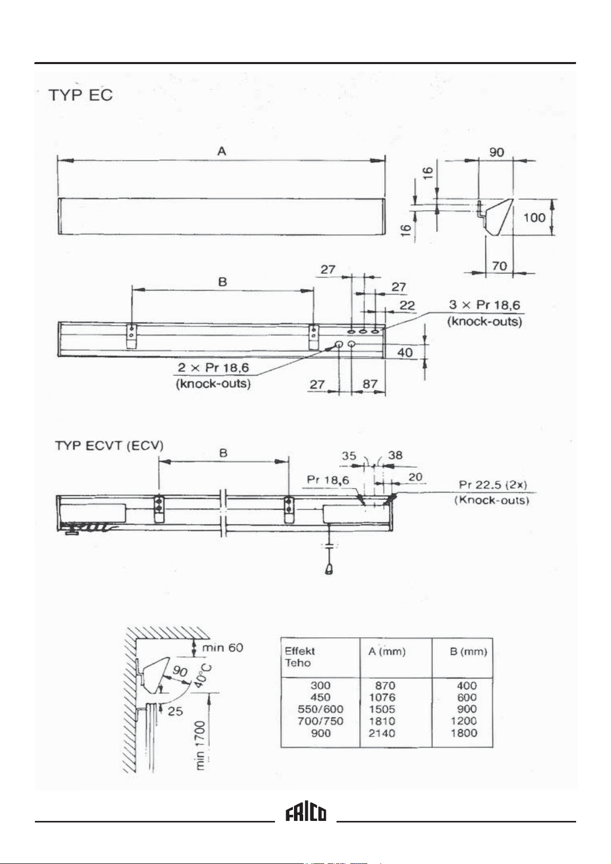
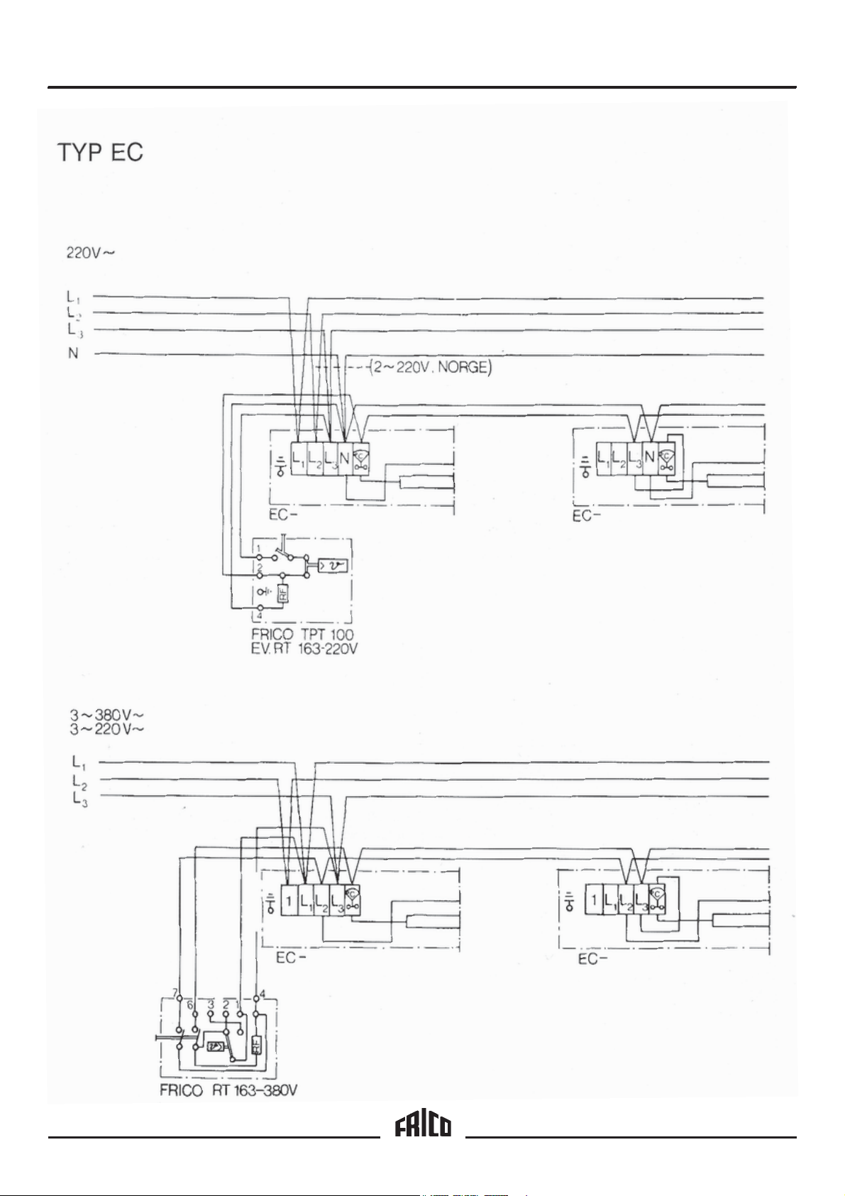
EC
The heater is regulated by means of a separate
room thermostat RPT/RT 163, which is mounted
on an outer wall at approximately 1.7 m above
floor level. Air to the heater is drawn through the
thermostat, which thereby senses the temperature
of the air in the room.
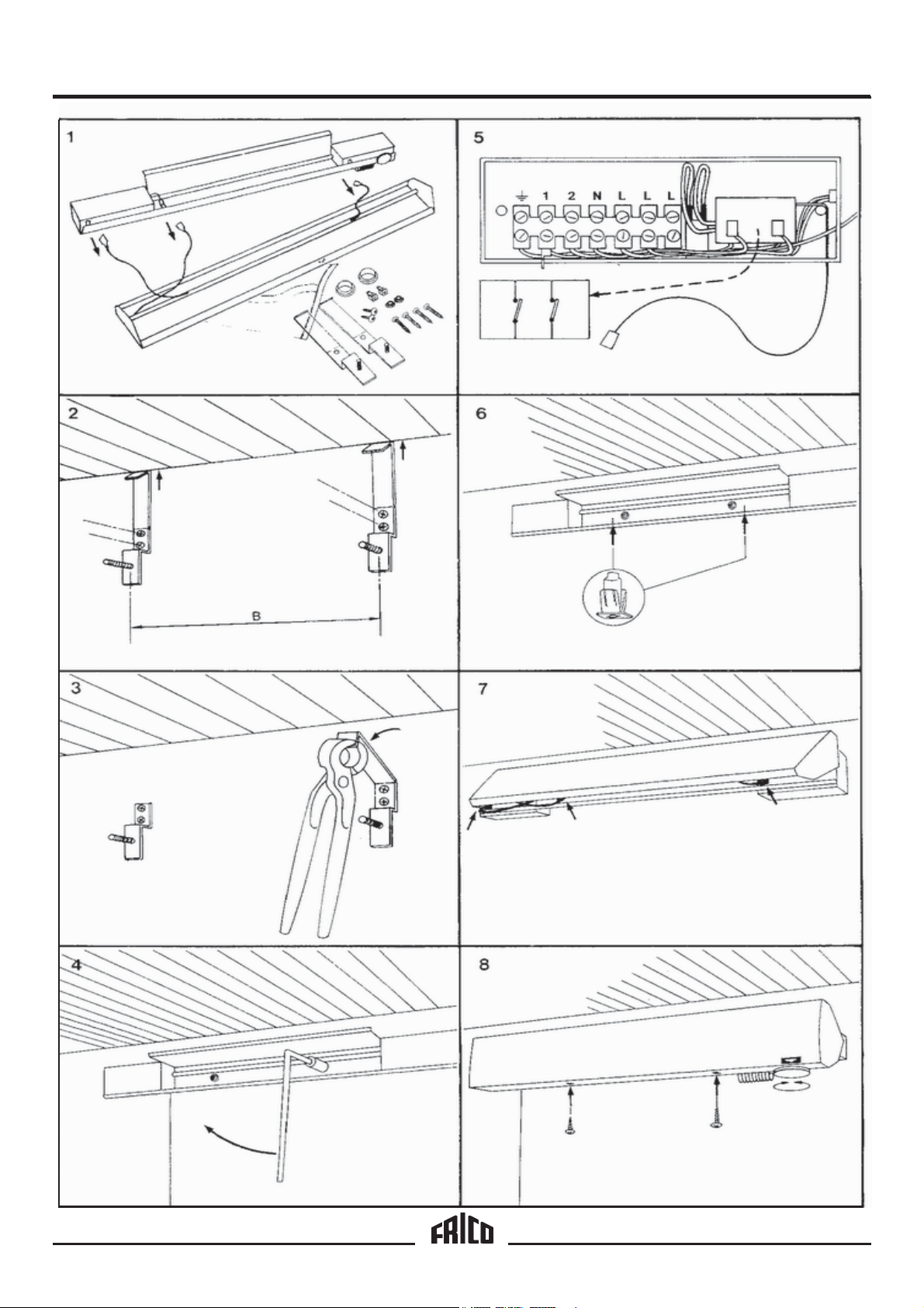
Fitting
1. Remove the front plate and detach the
electrical connection from the back plate.
2. Fit the brackets to the wall below the coving.
See Table B for distance between brackets.
Allow 15 mm for heater expansion.
3. Break off the top spacing part of the brackets at
the break mark.
4. Fasten the back plate to the brackets.
5. Extra terminal boards are provided in the heater
connection box for slave heater connection
(ECVT only). ECVT is fitted with a 2-pole circuit
breaker. Any further circuit breaker is
unnecessary.
6. Press the two plastic screw holders into place in
the bottom flange of the back plate.
7. Re-connect the wiring to the front panel and
hook it onto the top flange of the back plate.
8. Lower the front plate and screw into place via
the two plastic screw holders. For the ECVT, set
the thermostat at the required temperature.
Thermoplus is supplied ready for connection, for
example, via a switch.
If a Frico room thermostat regulates the heater (s),
the upper connection -L
removed. Refer to the wiring diagram on Page 4.
Thermoplus is equipped with extra terminal board
sections for further current distribution. A junction
box is therefore not required.
ECV – with two-pole control switch and
thermostat
The heater is connected by a power switch. A
warning lamp indicates that the heater is switched
on. The thermostat is fitted with a calibrated scale.
ECV
This heater is designed for slave connection to
ECVT. The total output of ECVT and ECV must not
exceed 3500 W at 220 V or 3800 W at 380 V. The
master heater controls the output of the slave
heaters.
on the primary heater is
3
8
Page 7

Page 8

Page 9

Page 10

We
Frico AB
Box 102
S-433 22 Partille
under own responsibility hereby declare that the following product(s)
Radient heaters: series Thermoplus
Type: EC-450, EC-600, EC-750 and EC-900
ECV-300, ECV-550 and ECV-700
ECVT-300, ECVT-550 and ECVT-700
which is(are) covered by this declaration of conformity comply with the
EC Electromagnetic Compatibility (EMC) Directive 89/336 /EEC & 92/31 EEC
EC Low Voltage Directive (LVD) 73/23/EEC
and is(are) manufactured in accordance with the following stated harmonised
standard(s) or other normative document(s).
EMC: EN 55 014: 1993
EN 60555-2/3: 1991
EN 55 104
Declaration of Conformity
LVD: CCA HD 251 S3:1982 incl. Am. 1-3
CCA HD 251 S1:1987 incl. Am. 1-5
Partille , 15 December 1995
Mats Careborg
Technical Manager
Page 11

Thermoplus
Main office
FRICO AB Tel: +46 (0)31 336 86 00
Box 102 Fax: +46 (0)31 26 28 25
S-433 22 Partille e-mail: mailbox@frico.se
SWEDEN http://www.frico.se
Norway
FRICO AS
Postboks 82, Alnabru Tel: +47 (0)2 272 38 44
N-0614 Oslo Fax: +47 (0)2 272 38 39
NORWAY e-mail: mailbox@frico.no
http://www.frico.no
For latetest updated information, see: www.frico.se
France
FRICO FRANCE Tel: +33 (0) 4 72 42 99 42
7, rue de la libération Fax: +33 (0) 4 72 42 99 49
F-69 270 Fontaines sur Saone e-mail: info@frico.fr
FRANCE
Russia
FRICO representative office in Russia
1 st Golutvinsky per., 3 Tel/Fax: +7 095 238 63 20
Moscow 109180 e-mail: frico@orc.ru
RUSSIA
 Loading...