

Frico Thermocassette HP Series, Thermocassette HP300, Thermocassette HP600, Thermocassette HP305, Thermocassette HP605 Mounting And Assembly Instruction
Page 1
Thermocassette HP
.... 6 ... 14.... 10 .... 12
... 16
FI
GB
RU
.... 8
... 18
FR NO DE SE
Page 2
Thermocassette HP
HP305
False ceiling
HP300/600
HP605
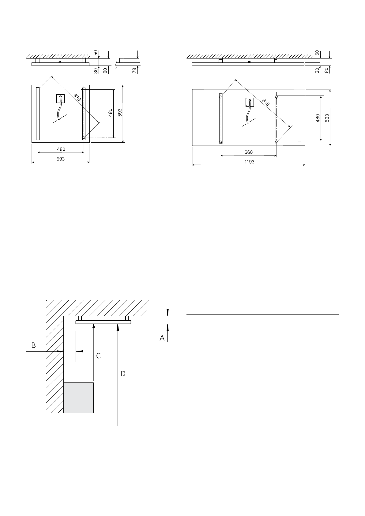
Minimum mounting distance
Fig. 1: Minimum mounting distance
Ceiling 80
Wall, long side of the unit 50
Wall, short side of the unit 50
Obstacle 500
Floor 1800
Min.distance
[mm]
2
Page 3
Mounting
Thermocassette HP
Fig. 1
A
Min 1,5 mm²
Max 2100 W
Fig. 2
C
B
D
E
Fig. 3
3
Page 4

Thermocassette HP
20
25
30
15
10
5
Technical specifications |
Type E-nr [SE] EL-nr [NO] Output (1)
Thermocassette HP. False ceiling model. Without brackets for false ceiling systems.
[W]
Voltage (2)
[V]
Amperage (3)
[A]
Max. surface
temperature (4)
[°C]
HP300 85 743 62 54 323 35 300 230V~ 1,30 100 5,4
HP600 85 743 64 54 323 36 600 230V~ 2,61 100 10,3
Protection class HP300/600: (IP20), normal design.
CE compliant.
Technical specifications |
Type E-nr [SE] EL-nr [NO] Output (1)
HP305 85 743 82 54 323 39 300 230V~ 1,30 100 5,8
HP605 85 743 84 54 323 41 600 230V~ 2,61 100 10,7
Thermocassette HP. Special model. With brackets.
[W]
Voltage (2)
[V]
Amperage (3)
[A]
Max. surface
temperature (4)
[°C]
Protection class HP305/605: (IP55), jet-proof design.
CE compliant.
Complies with the requirements for flammable areas according to SEMKO 111FF..
(1)
SE: Effekt
GB: Output
NO: Effekt
FR: Puissance
DE: Heizleistung
RU: Мощность
FI: Lämmitysteho
(3)
SE: Ström
GB: Amperage
NO: Strøm
FR: Intensité
DE: Stromstärke
RU: Ток
FI: Virta
(5)
SE: Vikt
GB: Weight
NO: Vekt
FR: Poids
DE: Gewicht
RU: Вес
FI: Paino
Weight (5)
[kg]
Weight (5)
[kg]
(2)
SE: Spänning
GB: Voltage
NO: Spenning
FR: Tension
DE: Spannung
RU: Напряжение
FI: Jännite
(4)
SE: Maximal yttemperatur
GB: Max. surface temperature
NO: Maksimal overflatetemp.
FR: Température de surface
DE: Max. Oberflächentemperatur
RU: Max. температура поверхности
FI: Suurin pintalämpötila
Accessories
ERP
Type E-nr [SE] EL-nr [NO] HxWxD
T10S 85 809 33 54 911 12 80x80x31
TK10S 85 809 34 54 911 13 80x80x31
KRT1900 85 810 12 54 910 50 165x57x60
ERP 85 820 05 54 238 86 153x93x40
ERPS 85 820 10 54 328 90 153x93x40
KRT1900T10S TK10S
[mm]
4
Page 5

Wiring diagrams HP
230V~
230V~
230V~
∼
Internal wiring diagram
Thermocassette HP
HP300, HP600 HP300, HP600
ERP/ T10S/TK10S
Output control
HP
ERP
K
230V~
HP
N
L
3
2
U
4
1
U K
G
G
HP
L
N
HP
L
N
L
N
Control by thermostat
Thermostat
P
N
HP
HP
L
N
HP
L
N
L
N
5
Page 6

GB
Thermocassette HP
Mounting and assembly instruction
General Instructions
Read these instructions carefully before
installation and use. Keep this manual for
future reference.
The product may only be used as set out in
the assembly and operating instructions. The
guarantee is only valid if the product is used
in the manner intended and in accordance
with the instructions.
Area of use
The heating panel is intended for the heating
of rooms requiring free walls. The panel
can be used for complete heating, or as an
additional heater (e.g. over a reception desk
or other work place).
There are two ratings: 300 W and 600 W.
The heating panel provides mainly radiation
heating. This implies that to obtain the
same experienced temperature it is possible
to reduce the air temperature in the room,
which saves energy.
Because of the low surface temperature,
max 100°C, the heating panel is suitable
for rooms with relatively low ceiling height.
Thanks to the location, the panel is protected
from any physical contact or damage. There
is no risk of being burned.
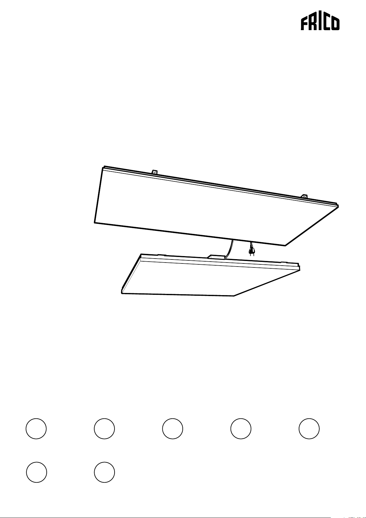
Design
1. Ceiling model: Intended as lay-in panel for
exposed grid. With cord, socket and plug,
which ensures simple extended connection
(max 2100 W from one wall socket).
2. Universal model in flush-proof design
(IP55): With better protection against
water. Delivered with cable without plug
and brackets.
One or more units have to be connected to
power line with a differential circuit breaker
rated at 30 mA. The cable section has to be at
2
least 1,5 mm
.
Units with cable and plug can be interconnected using the sockets on the back of
the heaters. The maximum power in interconnection is 2100 W.
If the units are to be extra insulated, then
this insulation must not exceed a value of
2
R=5 m
K/W.
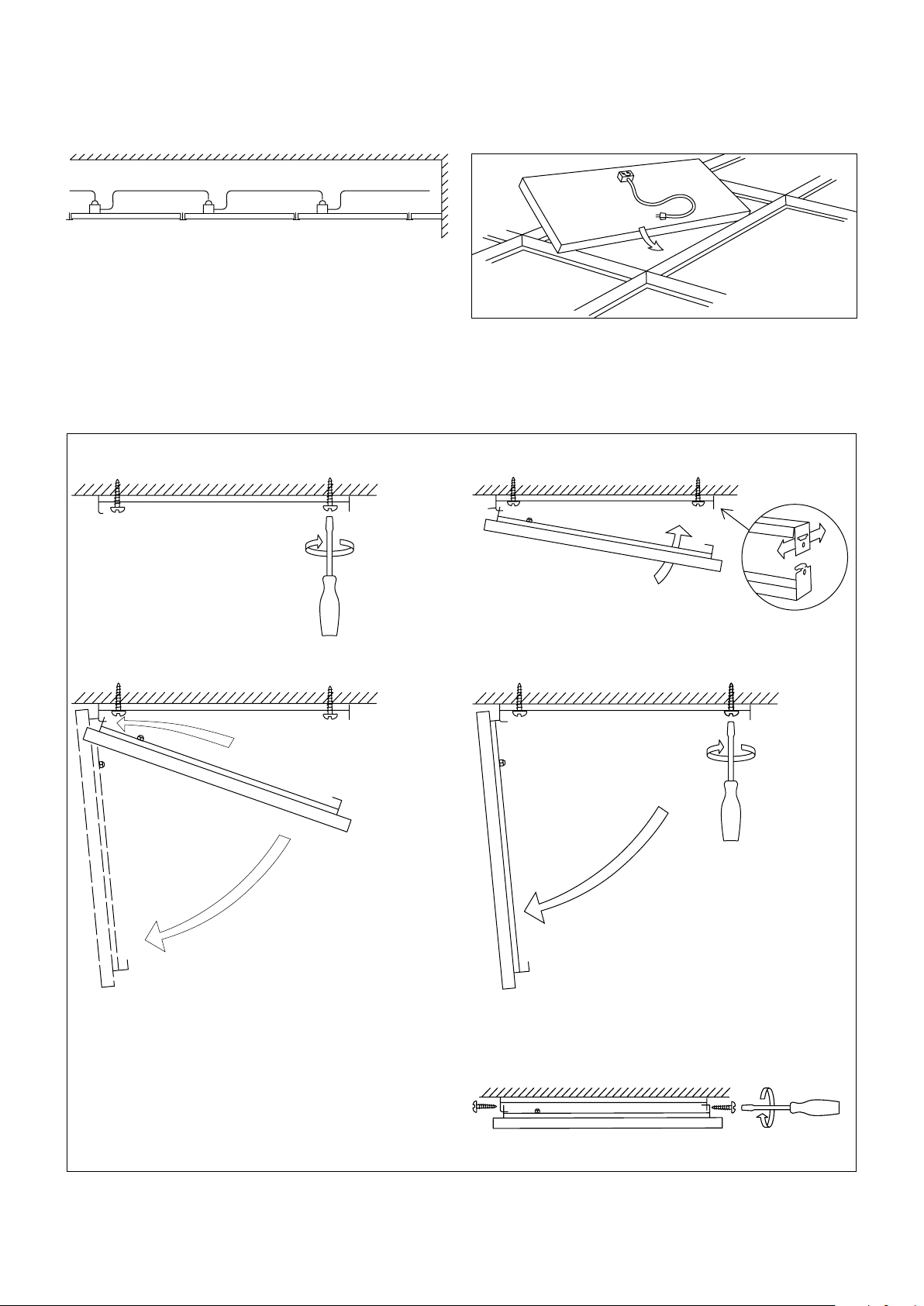
Mounting
Integrated in ceiling (put in exposed grid)
See fig. 2
1. Lateral distance to wall shall be at least
50 mm.
2. The heater(s) should only be wired by a
competent electrician, and in accordance
with existing national regulations. The
appliance should be preceded by an all
pole switch in accordance with existing
regulations (not applicable to versions with
a cord and plug).
3. Place the cassette in the required ceiling
square. Minimum design height ”H” for
dismounting, T-profile 32x15: 150 mm,
T-profile 38x24: 200 mm. NOTE! Avoid
fixing vertical bars in the T-profile where a
heating panel is to be installed. The panel
fills out the whole square.
4. Connect the panel.
5. The second last page in this mounting
instruction is to be filled out and fixed
adjacent to the distribution board and it
has to contain (drawing) the locations of
the heating units.
Bracket mounting
See fig. 3
1. Mounting height above floor shall be at
least 1,8 m, and lateral distance to wall at
least 50 mm. When mounting in gypsum
board, make sure that the mounting
brackets are anchored in the beam behind.
During long-term high temperatures the
strength of the board is reduced.
2. The heater(s) should only be wired by a
competent electrician, and in accordance
with existing national regulations. The
appliance should be preceded by an all
8
Page 7

Thermocassette HP
pole switch in accordance with existing
regulations (not applicable to versions with
a cord and plug).
3. Measure, drill and screw the two loose
brackets to the ceiling. Do not tighten the
screws yet. It is important that the holes
come at right angles, cross measure. (fig.
3A)
4. Hook the panel brackets to the ones on the
ceiling (only the side nearest to the cable
gland). Allow panel to hang vertical. (fig.
3B)
5. Connect the panel.
6. Swing up the panel, and adjust the lateral
position of the ceiling mounted brackets.
(fig. 3C)
7. Swing down the panel and tighten the
screws in the ceiling. (fig. 3D)
8. Swing up the panel again and hook the
panel bracket ends in the ceiling brackets.
NOTE! Make sure that the brackets do not
become unhooked at the other end.
9. Secure the panel with a screw (enclosed
on delivery) at each hanging point. (fig.
3E)
10.The second last page in this mounting
instruction is to be filled out and fixed
adjacent to the distribution board and it
has to contain (drawing) the locations of
the heating units.
GB
Replacement of cable for HP305 or HP605
1. Because of limitations in the IP55 category
the cable cannot be changed.
2. If the cable is damaged the unit has to be
scrapped.
Safety
This appliance is not intended for use by
persons (including children) with reduced
physical, sensory or mental capabilities, or
lack of experience and knowledge, unless they
have been given supervision or instruction
concerning use of the appliance by a person
responsible for their safety. Children should
be supervised to ensure that they do not play
with the appliance.
9
Page 8

Page 9

Page 10

Page 11

Place this drawing adjacent to the distribution board
OBS!
– do not restrict the thermal emission of the heated ceiling;
– do not affix materials other than those recommended
– do not insert nails or screws
HP300, 300W, 220-240V
HP305, 300W, 220-240V
HP600, 600W, 220-240V
HP605, 600W, 220-240V
Drawing of the installation
Page 12

Main offi ce
Frico AB Tel: +46 31 336 86 00
Box 102 Fax: +46 31 26 28 25
SE-433 22 Partille mailbox@frico.se
Sweden www.frico.se
For latest updated information and information
about your local contact: www.frico.se
Item no: 204773, 20100601 HH
 Loading...