

Page 1
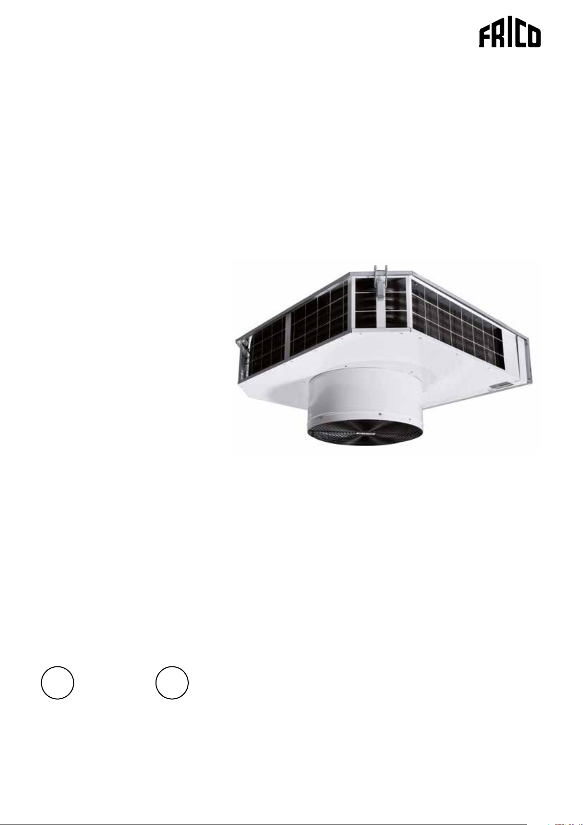
SWT
SE
.... 10
GB
.... 12
Art no: 172781-01
Page 2
C
F
E
Fan heater SWT
SWT
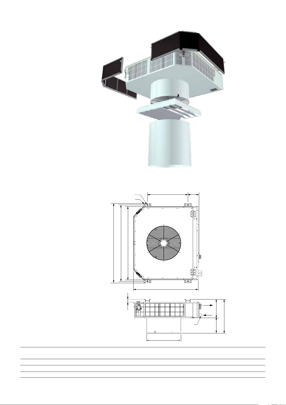
1. Fan heater SWT
2. Filter SWTCF
3. Air director SWTCL
4. Extension collar SWTCE
2
1
3
4
Fig 1: Accessories
Dimensions
Ø12 (4x)
Ø5,5(16x)
D
B
A
30
ØM
G
H
K
Fig 2: Dimensions
ØL
Type A
[mm]B [mm]C[mm]D[mm]E[mm]F[mm]G[mm]H[mm]K[mm]ØL[mm]ØM[mm]
SWT02 535 640 280 670 705 125 195 330 135 305 22
SWT12 675 760 420 790 825 115 195 355 160 355 22
SWT22 735 1070 480 110 0 113 5 110 300 415 11 5 430 28
2
Page 3
Mounting
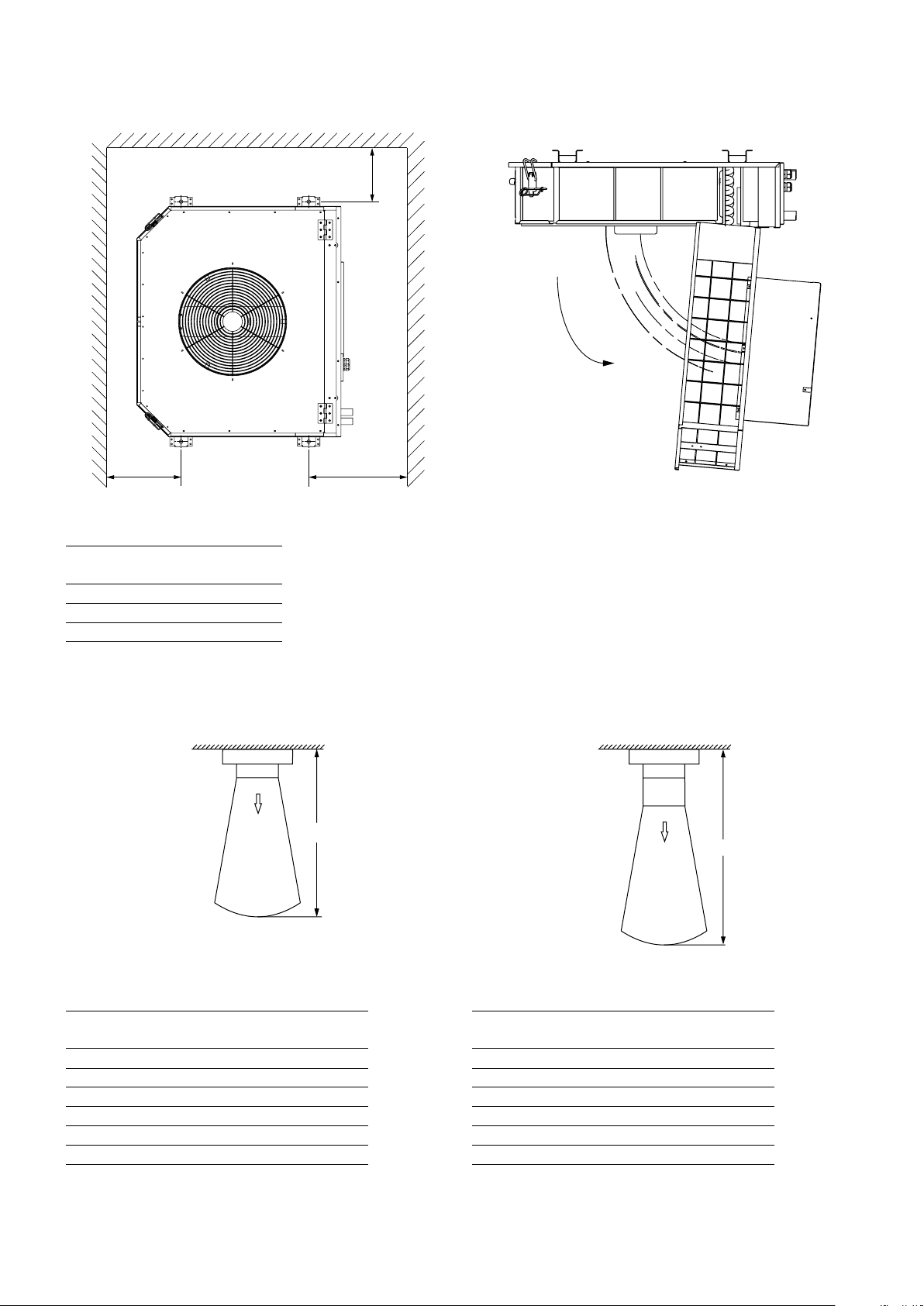
Min 600mm Min 800mm
SWT
Min 600mm
Fig. 3: Minimum mounting distance
Type A
[mm]
B
[mm]
SWT02 280 640
SWT12 420 760
SWT22 480 1070
Air throw
STANDARD
0,2m/s
Fig. 4: To open
SWTCE
K
K
0,2m/s
Fig. 5: Without accessories Fig. 6: With accessories
Type Fan position K* - STANDARD
[m]
SWT02 high 4,0
low 2,2
SWT12 high 4,5
low 2,7
SWT22 high 7, 5
low 4,5
*) The air throw is defined as the distance in a straight angle from the fan heater to the point where the air speed has dropped to 0,2
m/s. Outlet temperature is +40 °C and room temperature is +18 °C.
Type Fan position K* - SWTC
[m]
SWT02 high 7, 0
low 4,0
SWT12 high 8,0
low 5,0
SWT22 high 12,0
low 7, 0
3
Page 4
SD20
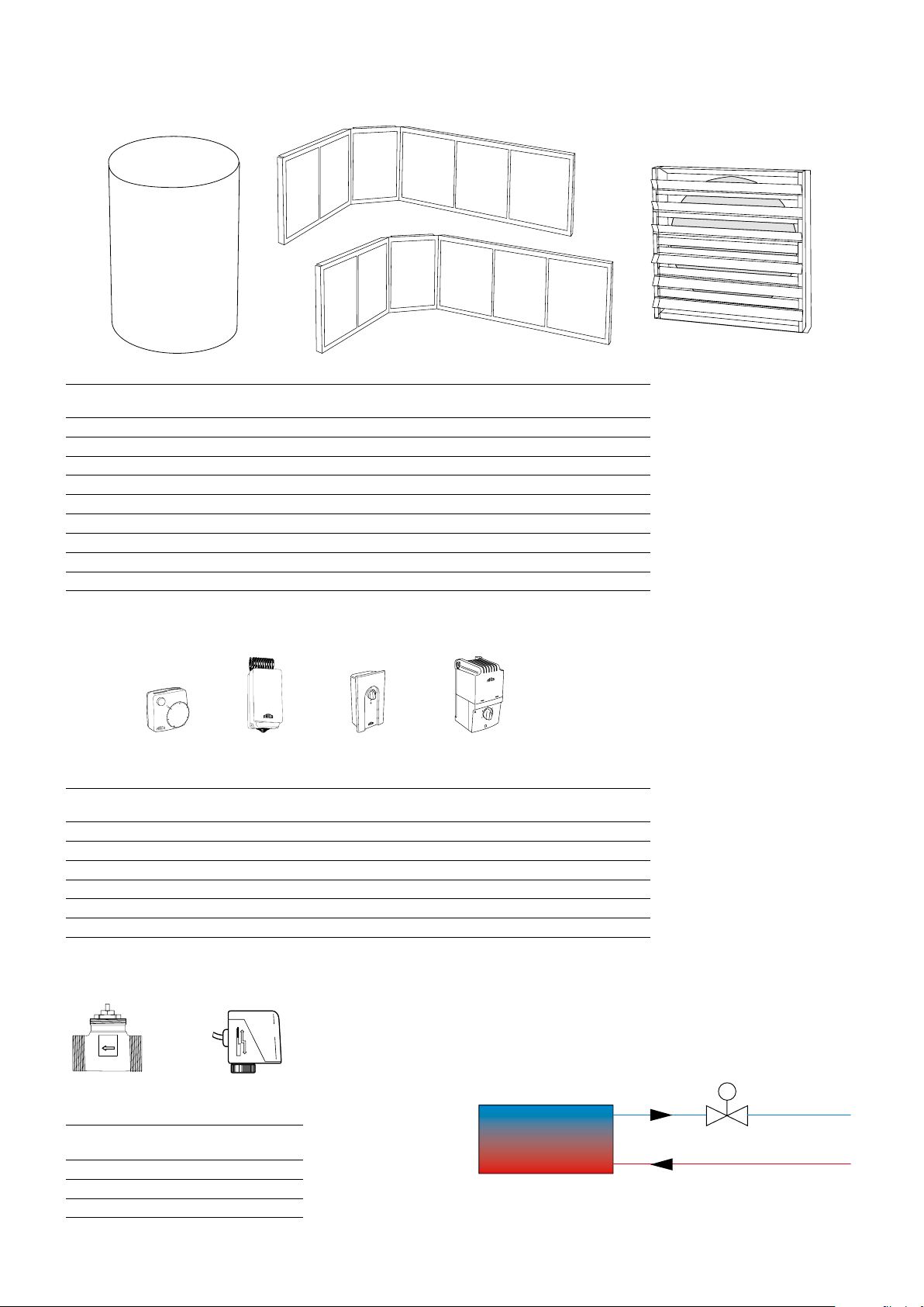
Accessories
SWT
Type Description HxWxD
[mm]
SWTCE02 Extension collar 350 mm for SWT02
SWTCE12 Extension collar 350 mm for SWT12
SWTCE22 Extension collar 350 mm for SWT22
SWTCF02 Filter for SWT02 (2 pcs)
SWTCF12 Filter for SWT12 (2 pcs)
SWTCF22 Filter for SWT22 (2 pcs)
SWTCL02 Air director for SWT02 362x362x59
SWTCL12 Air director for SWT12 412x412x67
SWTCL22 Air director for SWT22 482x482x67
Controls
15
10
20
5
25
30
TKS16
KRT1900
Type Description HxWxD
TKS16 Electronic thermostat with knob and 1-pole main switch 80x80x31
KRT1900 Capillary tube thermostat 165x57x60
CB20 2-step change-over switch for air flow, max 10A 155x87x43
RE1,5 5-step change-over switch for air flow, max. 1,5A 200x105x105
RE3 5-step change-over switch for air flow, max. 3A 200x105x105
RE7 5-step change-over switch for air flow, max. 7A 247x147x145
CB20
RE1,5/3/RE7
[mm]
Water regulation
SD20
Type RSK-nr
SD20 672 70 37
TVVS20
TVVS25
TVVS20/25
(SE)
673 92 96
673 92 97
4
TVVS20/25
Page 5
230 V~
230 V~
230 V~
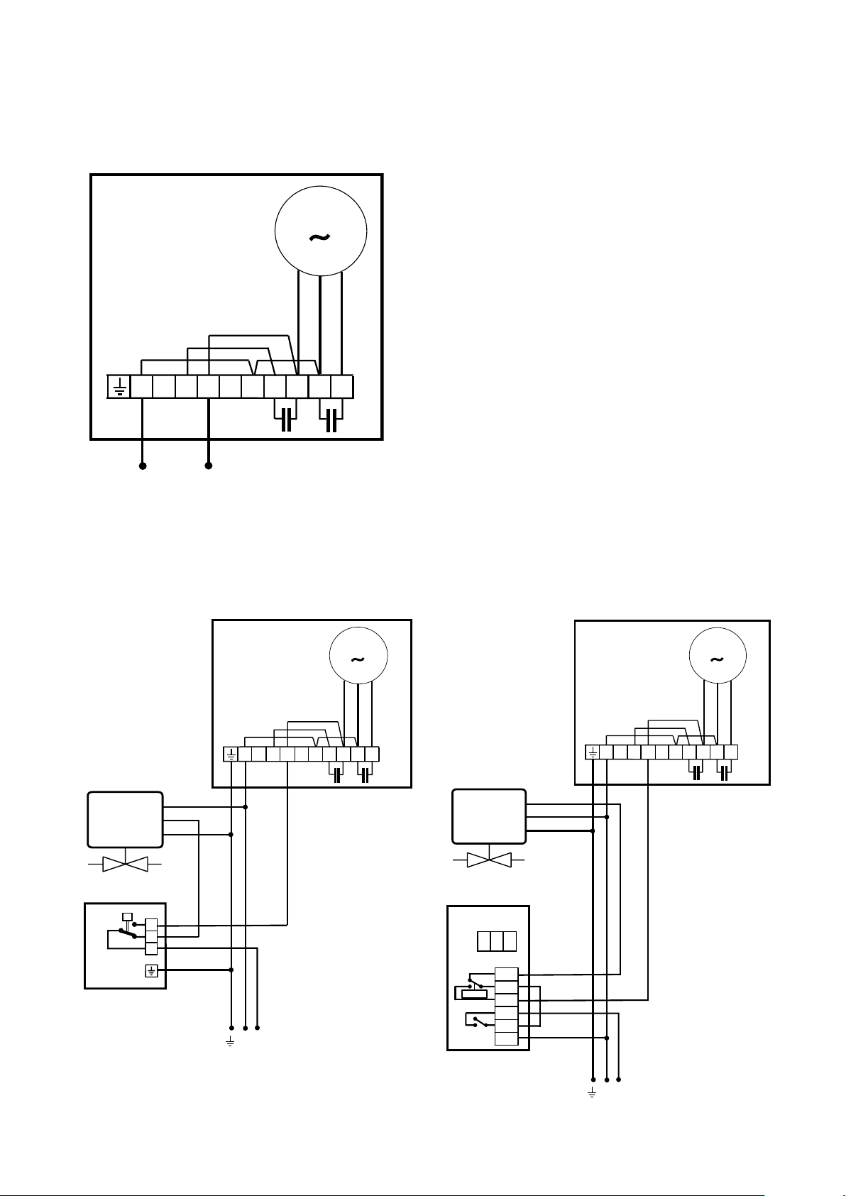
Wiring diagrams SWT
Internal
SWT
M
~
Brown
Black
SWT
Blue
N
N
1
3456
2
L
Control by thermostat only
SWT
1
N
78
3456
2
9
M
~
Brown
78
SWT
M
~
Black
Brown
78
Blue
9
Black
Blue
3456
1
N
9
2
SD20
TVVS20/25
KRT
3
2
1
N
SD20
TVVS20/25
TKS16
A/B
5
6
>t°C
7
2
2o
L
4
N
L
5
Page 6
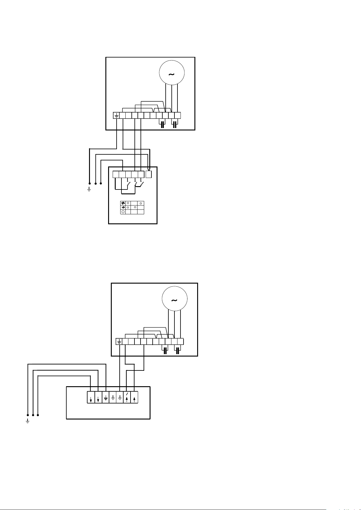
2-step control of airflow only
SWT
Brown
M
~
Black
SWT
Blue
1
N
L
230 V~
CB20
5-step control of airflow only
SWT
1
N
2
3
24
3456
5
7
78
M
~
9
L
230 V~
6
N
N
RE1,5 - 7
Black
Brown
Blue
3456
1
N
2
~
~
N
78
9
Page 7
230 V~
230 V~
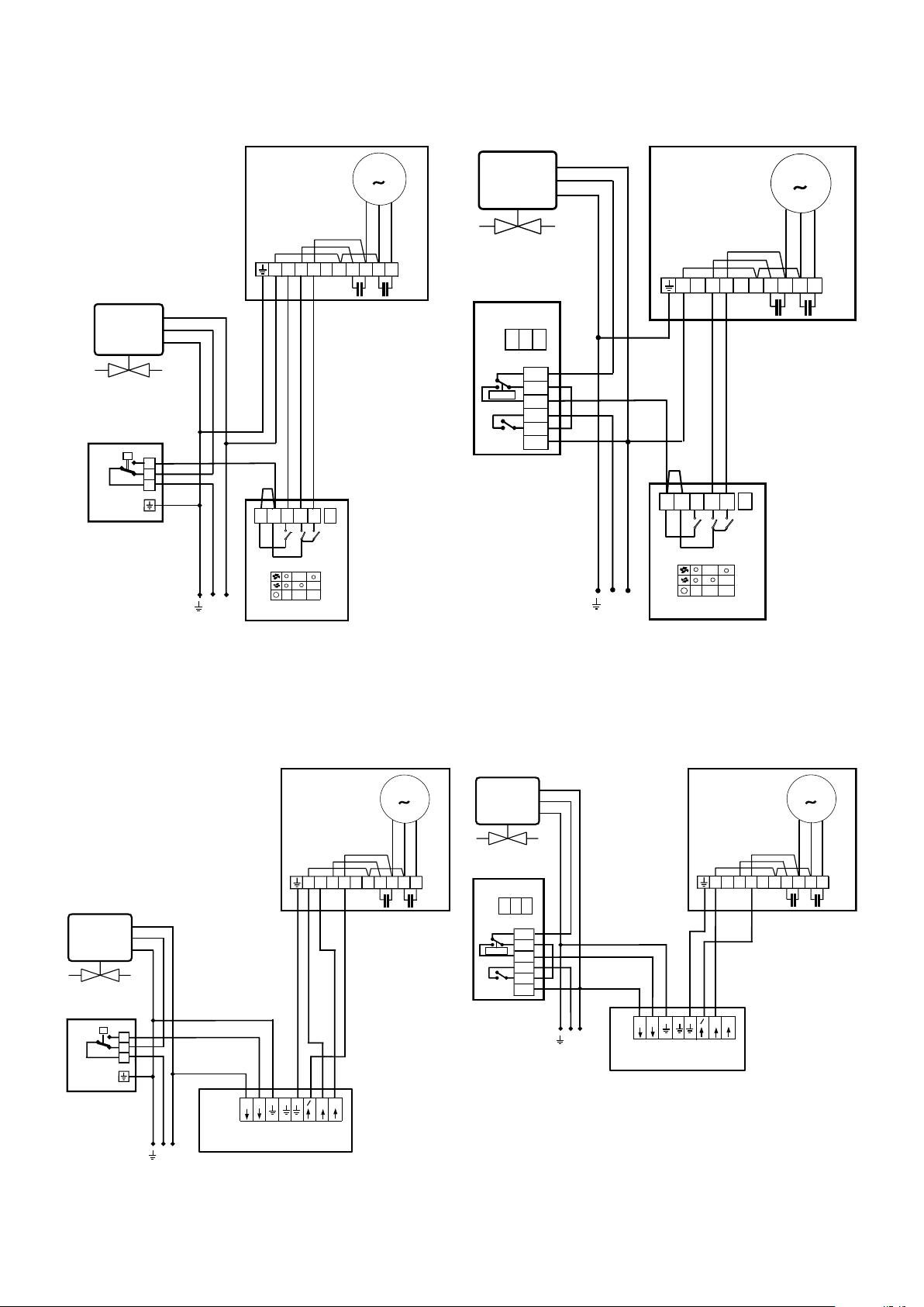
Thermostat and 2-step control
SWT
SD20
TVVS20/25
3
2
1
KRT
SWT
Brown
M
~
Black
Blue
SD20
TVVS20/25
3456
1
N
2
78
9
SWT
N
1
3456
2
M
~
Brown
78
Black
Blue
9
TKS16
A/B
5
6
>t°C
7
2
2o
4
5
3
24
N
1
CB20
5
3
24
1
N
L
CB20
7
L
7
Thermostat and 5-step control
SWT
1
N
SD20
TVVS20/25
3
2
1
KRT
~
N
~
N
3456
2
~
M
~
Brown
78
SWT
SD20
Black
Blue
9
TVVS20/25
TKS16
5
6
>t°C
7
2
2o
4
A/B
L
230 V~
3456
1
N
2
~
~
N
N
RE1,5 - 7
~
N
M
~
Brown
78
Black
Blue
9
L
N
230 V~
RE1,5 - 7
7
Page 8

Technical specification | Fan heater SWT 2
SWT
Type Heat (1)
output*
[kW]
1
Air flow (2)
[m3/h]
Air flow(2)
[m3/s]
Sound (3)
2
level*
[dB(A)]
∆t*
[°C]
1,3
Air throw*4
(4a)
[m]
Air throw*4 (4b) with
extension collar
[m]
SWT02 7,8/11 700/1100 0,19/0,31 37/53 33/29 2,2/4 4/7
SWT12 14/18 1300/2000 0,36/0,56 44/57 25/22 2,7/4,5 5/8
SWT22 29/40 2500/3900 0,69/1,08 48/60 34/30 4,5/7,5 7/12
Type Water (5)
volume*5
[l]
Voltage (6)
[V]
Amperage (7)
[A]
LxWxH (8)
[mm]
Weight (9)
[kg]
RSK
(SE)
NRF
(NO)
SWT02 1,2 230V~ 0,4 705x535x330 19 672 67 03 850 23 11
SWT12 1,7 230V~ 0,6 825x625x355 26 672 67 04 850 23 12
SWT22 3,9 230V~ 1,0 1135x735x415 41 672 67 05 850 23 13
*1) Applicable at water temperature 80/60 °C, air temperature, in +15 °C.
2
*
) Conditions: Distance to the unit 5 metres.
3
) ∆t = temperature rise of passing air at maximum heat output and lowest/highest airflow.
*
*4) The air throw data above is valid when the horizontally adjustable air director is used and the outlet temperature is +40 °C and the
room temperature is +18 °C. The air throw is defined as the distance in a straight angle from the fan heater to the the point where the
air speed has dropped to 0,2 m/s.
5
*
) Water volume inside battery.
Protection class: (IPX4), splash-proof design.
CE compliant.
(1)
SE: Värme effekt
GB: Heat output
(2)
SE: Luftflöde
GB: Air flow
(3)
SE: Ljudnivå
GB: Soud level
(4a)
SE: Kastlängd
GB: Air distribution
(4b)
SE: Kastlängd med förlängningsstos
GB: Air distibution with extension sleeve
(5)
SE: Vattenvolym
GB: Water volume
(6)
SE: Spänning
GB: Voltage
(7)
SE: Ström
GB: Amperage
(8)
SE: LxBxD
GB: LxWxH
(9)
SE: Vikt
GB: Weight
8
Page 9

SWT
Output charts water
Incoming / outgoing water temperature 80/60 °C
Air temp. in = +10 °C Air temp. in = +15 °C Air temp. in = +20 °C
Type Fan
SWT02 max 0,31 12,0 42 0,15 11,2 10,8 44 0,13 9,3 9,6 46 0,11 7, 5
SWT12 max 0,56 20,3 39 0,25 17, 8 18,4 42 0,23 14,8 16,5 44 0,20 12,1
SWT22 max 1,08 44,0 43 0,53 14,0 39,6 45 0,48 11,5 35,5 47 0,43 9,3
Type Fan
SWT02 max 0,31 7, 5 30 0,09 4,9 6,4 40 0,08 3,8 5,3 34 0,06 2,7
SWT12 max 0,56 13,0 29 0,16 8,3 11,1 31 0,13 6,3 9,2 34 0,11 4,4
SWT22 max 1,08 27,1 30 0,33 5,9 23,2 33 0,28 4,5 19,3 35 0,23 3,2
Air-
pos.
flow
[m³/s]
min 0,19 8,7 46 0,10 6,2 7, 8 48 0,09 5,1 6,9 50 0,09 4,1
min 0,36 15,4 44 0,19 10,7 13,9 46 0,17 9,0 12,5 49 0,15 7, 4
min 0,69 32,0 47 0,39 7,8 28,9 49 0,35 6,5 25,7 51 0,31 5,2
Air-
pos.
flow
[m³/s]
min 0,19 5,4 33 0,06 2,8 4,6 34 0,06 2,1 3,8 36 0,05 1,5
min 0,36 9,9 32 0,12 5,1 8,4 34 0,10 3,8 7, 0 36 0,09 2,7
min 0,69 19,9 33 0,24 3,4 16,8 35 0,20 2,5 14 37 0,17 1,8
Output
[kW]
Incoming / outgoing water temperature 60/40 °C
Air temp. in = +10 °C Air temp. in = +15 °C Air temp. in = +20 °C
Output
[kW]
Air
temp.
out.
[°C]
Air
temp.
out.
[°C]
Water
flow
[l/s]
Water
flow
[l/s]
Pressure
drop
[kPa]
Pressure
drop
[kPa]
Output
[kW]
Output
[kW]
Air
temp.
out.
[°C]
Air.
temp.
out.
[°C]
Water
flow
[l/s]
Water
flow
[l/s]
Pressure
drop
[kPa]
Pressure
drop
[kPa]
Output
[kW]
Output
[kW]
Air.
temp.
out
[°C]
Air.
temp.
out
[°C]
Water
flow
[l/s]
Water
flow
[l/s]
Pressure
drop
[kPa]
Pressure
drop
[kPa]
Incoming / outgoing water temperature 55/45 °C
Air temp. in = +10 °C Air temp. in = +15 °C Air temp. in = +20 °C
Type Fan
SWT02 max 0,31 8,1 34 0,20 20,5 6,9 34 0,17 15,4 5,8 36 0,14 11,1
SWT12 max 0,56 13,6 26 0,33 31,9 11,7 32 0,28 24,3 9,9 34 0,23 16,8
SWT22 max 1,08 32,1 33 0,71 25,6 25,3 34 0,62 19,1 21,2 37 0,51 13,7
Air-
pos.
flow
[m³/s]
min 0,19 5,8 34 0,14 11,2 5,0 36 0,12 8,4 4,2 38 0,10 6,1
min 0,36 10,3 30 0,25 19,2 8,8 35 0,21 14,7 7, 5 36 0,18 10,1
min 0,69 21,5 35 0,52 14,1 18,4 37 0,45 10,6 15,4 39 0,37 7, 6
Output
[kW]
Air
temp.
out.
[°C]
Water
flow
[l/s]
Pressure
drop
[kPa]
Output
[kW]
Air.
temp.
out.
[°C]
Water
flow
[l/s]
Pressure
drop
[kPa]
Output
[kW]
Air.
temp.
out
[°C]
Water
flow
[l/s]
Pressure
drop
[kPa]
9
Page 10

SE
SWT
Montage- och bruksanvisning
Allmänna anvisningar
Läs noga igenom denna bruksanvisning före
installation och användning. Spara manualen
för framtida bruk.
Produkten får endast användas till det
som framgår av denna montage- och
bruksanvisning. Garantin gäller endast
om anvisningen har följts och produkten
använts såsom är beskrivet.
Användningsområde
Fläktluftvärmare SWT är en fläktluftvärmare
för vattenanslutning.
SWT används för uppvärmning av entréer,
lager, industrilokaler, verkstäder, sporthallar,
garage och butiker.
Fläktluftvärmaren monteras direkt mot tak
eller i takpendlar. Den låga bygghöjden gör att
SWT även kan byggas in i undertak.
Kapslingsklass: IPX4.
Aggregatet består av:
Hölje av vitlackerad galvaniserad stålplåt.
Frontplåt med gångjärn kan öppnas för
invändig rengöring.
Fläktenhet består av en kullagrad motor
med termoskydd. Kapslingsklass IP44. Max
omgivningstemperatur +30 °C.
Värmebatteri med lameller i aluminium
och rör i koppar. Röranslutningar SWT02 och
SWT12 22 mm och SWT22 28 mm.
Avsedd för pumpvarmvatten upp till
+80 °C och 10 bar i standardutförande.
Värmebatterierna provtrycks med 15 bar.
Montering
Aggregatet levereras med hölje, konsoler, fläkt
och värmebatteri i grundutförande.
Om flera takvärmare ska monteras i samma
lokal, se till så att de fördelas jämt och att de
inte blåser så att de stör arbetsmiljön.
Fläktluftvärmare SWT monteras direkt mot
tak eller i takpendlar. Skruva fast värmaren i
taket med fyra skruvar i konsolerna. Behöver
värmaren pendlas ner, använd takpendlar till
lämplig nivå. Borrmall och minavstånd till
vägg se fig. 2 och fig. 3.
Om takkonstruktionen är svag måste den
förstärkas så att en säker installation uppnås.
För vikter på varje storlek, se tabell sid. 8.
Montering av förlängningsstos SWTCE
Vid högt montage kan utloppsstosen på SWT
förlängas. Detta ökar kastlängden på luften, se
fig.6.
Montera förlängningsstosen på
utloppsstosen.
Montering av luftriktare SWTCL
För att undvika drag vid låga bygghöjder
kan luftriktare monteras för att få en bättre
riktning av luften i sidled.
Montera luftriktaren på utloppsstosen.
Montering av filter SWTCF
Med monterat filter förlängs intervallen för
rengöring av vattenbatteriet.
Lossa excenterlåsen på fläktplåten och låt
den hänga ner. Haka nu i de båda hakarna på
filtret SWTCF i gallret.
Installation av värmebatteri
Installationen ska utföras av behörig
installatör. Vatteninloppet ansluts på
värmarens lägst placerade rör och utloppet,
med eller utan ventil, på det högst
placerade. Vid åtdragning av kopplingar
på anslutningsrör eller ventiler ska dessa
hållas fast så att vridkraft inte överförs till
värmefläktens in- och utloppsrör.För korrekt
in- och utloppsanslutning av värmebatteriet,
se måttskiss fig.2. Vattenbatteriet får ej
anslutas till färskt eller syresatt vatten
(tappvarmvatten). Innan drifttagning ska
värmebatteriet luftas. Luftningsventil ska
anslutas på högpunkt utanför aggregatet eller
på utloppsrör i anläggningen. Luftnings- och
avtappningsventil ingår inte i aggregatet.
Aggregat som kan utsättas för frysrisk, ska
utrustas med extern frysskyddsautomatik för
att säkerställa att vattenbatteriet inte fryser
sönder.
10
Page 11

SWT
SE
Elinstallation
Installationen ska föregås av en allpolig
brytare med ett brytavstånd om minst 3 mm
och ska utföras av behörig installatör och i
enlighet med gällande föreskrifter.
Fläktluftvärmare SWT är avsedd för fast
installation och kopplas in via knock-outs
på värmarens baksida. Motorn har inbyggd
termokontakt till skydd mot överhettning.
Återställningen av denna sker automatiskt då
motorn har svalnat.
Använda kabelgenomföringar måste
säkerställa kravet på kapslingsklass!
Efter inkoppling av motorn, kontrollera
rotationsriktning på fläktbladen. Dessa ska
rotera motsols, sett från fläktens inloppssida.
Se kopplingsscheman.
Uppstart
OBS! Vid första användningstillfället eller
vid uppstart efter ett längre uppehåll, kan
en mindre rök- och luktutveckling tillfälligt
förekomma, vilket är helt normalt.
Säkerhet
Säkerställ att området kring apparatens
insugs- och utblåsgaller hålls fritt från
materiel som kan hindra luftströmmen
genom apparaten!
• Apparaten kan ha heta ytor vid drift!
• Denna apparat kan användas av barn
över 8 år och av personer med nedsatt
fysisk, känslomässig eller mental förmåga,
och av personer med bristande erfarenhet
eller kunskap, under förutsättning att de
övervakas eller att de får anvisningar
angående säker användning av apparaten
och dess inneboende faror. Barn får ej leka
med apparaten. Rengöring och underhåll
skall utföras av användaren och får inte
utföras av barn utan övervakning.
• Lyfthjälpmedel ska användas för att lyfta
apparaten.
Underhåll och skötsel
För att säkerställa aggregatets prestanda och
driftsäkerhet ska regelbunden inspektion och
rengöring ske. Inspektion bör göras minst två
gånger per år och rengöring vid behov.
Vid inspektion och service ska
strömförsörjningen alltid brytas.
Rengöring av fläkt
Gör värmaren spänningslös. Lossa
excenterlåsen på fläktplåten och låt den
hänga ner. Blås rent vattenbatteriet med
tryckluft inifrån och ut. Rengör fläktvinge
och skyddsgaller med en mjuk borste. Om
ånga eller vatten används vid rengörningen
ska fläktmotorn skyddas mot vatten.
Tidsintervallerna mellan varje rengöring beror
på vilken miljö som fläkten arbetar i och om
filter varit monterat eller inte.
11
Page 12

GB
SWT
Assembly and operating instructions
General Instructions
Read these instructions carefully before
installation and use. Keep this manual for
future reference.
The product may only be used as set out in
the assembly and operating instructions. The
guarantee is only valid if the product is used
in the manner intended and in accordance
with the instructions.
Application
Fan heater SWT is a fan heater for water
connection.
SWT is used for heating of entrances,
storages rooms, industrial premises,
workshops, sports arenas, garages and shops.
The fan heater is mounted directly on the
ceiling or in drop rods. The low construction
height makes SWT suitable for recessed
mounting in false ceiling.
Protection class: IPX4
The unit consists of the following:
Casing of white powder coated galvanized
steel sheet.
The front with hinges can be open for
maintenance.
Fan unit
Motor with ball bearing and thermal
protection. Protection class IP44. Maximum
surrounding temperature: +40 °C.
Water heating coil
Heating coil with aluminium fins and copper
tubes. Connections SWT01 and SWT12 Ø22
and SWT22 Ø28.
In standard designs, SWT is intended for hot
water up +80 °C and 10 bar. The heating coils
are pressure tested for 15 bar.
Mounting
The unit is delivered with casing, brackets,
fan and heating coil as standard. If several
fan heaters are installed in the same premises,
ensure that they are uniformly distributed
and that they deliver air so that the working
environment will not be disturbed.
The fan heater is mounted directly on the
ceiling or in drop rods. Secure the fan heater
to the ceiling with four screws through the
brackets. Drop rods are used when mounting
at a distance from ceiling. For drilling
template, see fig. 2 and fig. 3.
If the ceiling structure is weak, it must be
reinforced to ensure safe installation. For
particulars of weights of each size, see table
p. 8.
Mounting of the extension collar SWTCE
If the fan heater is mounted at a high level,
the outlet collar of the SWT can be replaced
by a longer collar. This increases the air throw
of the fan heater, see fig. 6.
Mount the extension collar on the outlet
collar.
Mounting of the air director SWTCL
To avoid draught in cases of low installations,
air directors can be mounted to get a better
direction of the air sideways.
Mount the air director on the outlet collar
Mounting of the filter SWTCF
When filter is mounted the intervals for
cleening the water coil inrcreases.
Loosen the clamps on the fan plate and let
it hang down. Now hook the two hooks on the
filter into the grid.
Connection of heating coil
The installation should be carried out
by a certified installer. The water inlet is
connected to the heaters lowest pipe and the
outlet, with or without valve, to the highest
placed pipe. For correct inlet and outlet
connection, see dimension sketch fig.2. Be
careful while connecting the pipes to prevent
pipe damage and water leakage.
The heating coil must not be connected to
a mains pressure water system or an open
water system.
Prior to use, the pipe system should be
ventilated. The air valve should be connected
on a high point in the pipe system. Air and
draining valves are not included in the
heating coil.
Units that are likely to be exposed to air
12
Page 13

SWT
GB
temperatures below zero should be equipped
with external frost protection to ensure that
the heating coil is not damaged by frost.
Electrical installation
The electrical installation should be carried
out by a qualified electrician in conformity
with prevailing regulations. The appliance
should be preceded by an triple-pole switch
with at least 3 mm breaking gap.
Fan heater SWT is intended for fixed
installation and is connected by knock-outs
on the heaters back side.
The motor has a built-in thermal safety
cut-out to protect against overheating. This
will reset automatically once the motor has
cooled.
Cable glands used must guarantee the
protection class requirements.
After the electrical installation of the motor,
check the rotation of the fan. Seen from the
inlet side, the impellers should be rotating
anti-clockwise.
See wiring diagrams.
Start-up
When the unit is used for the first time or
after a long period of disuse, smoke or odour
may result from dust or dirt that has collected
on the element. This is completely normal
and disappears after a short time.
damage the bearings. If the vibrations/noise
remain after cleaning, please contact a
certified technician.
Loosen the clamps on the fan plate and let
it hang down. Use compressed air from the
inside out to clean the water coil. Use a soft
brush to clean the impellers. If water or steam
is used for cleaning, ensure that the motor is
protected from water.
Safety
• Ensure that the area around the intake
is kept free from material which could
prevent the air flow through the appliance!
• The appliances have hot surfaces during
operation!
• This appliance can be used by children
aged from 8 years and above and persons
with reduced physical, sensory or
mental capabilities or lack of experience
and knowledge if they have been given
supervision or instruction concerning
use of the appliance in a safe way and
understand the hazards involved. Children
shall not play with the appliance. Cleaning
and user maintenance shall not be made
by children without supervision.
• Lifting aids should be used to lift the
appliance.
Maintenance
To ensure performance and reliability of
the unit, inspection and cleaning should be
carried out regularly. Inspection should be
carried out at least twice a year. Clean the
unit when needed. During inspection the
power supply must always be disconnected.
Cleaning the fan
Cleaning intervals of the fan is due to filter (if
any) and air quality.
To ensure performance and reliability of
the unit, inspection and cleaning should be
carried out regularly. Inspection should be
carried out at least twice a year. Clean the
unit when needed. During inspection the
power supply must always be disconnected.
If the impellers are not cleaned properly,
vibrations/noise can occur and severely
13
Page 14

Page 15

Page 16
Main offi ce
For latest updated information and information
about your local contact: www.frico.se
2014-03-27 HH/SÅ/SÄ
 Loading...