

Frico SLW400, SLW800, SLW600 Original Instructions Manual
... 2
SE
... 27
GB
SLW
Original instructions

Conformity 28
Symbols 28
Editiorial pictograms 28
Safety pictograms 28
1 General 29
1.1 General warnings 29
1.2 Essential safety rules 30
1.3 Product range 30
1.4 Nominal technical features 30
1.5 Dimensions SLW - 2 tubes 31
1.6 Transport dimensions and weight 31
2 Installation 32
2.1 Positioning the unit 32
2.2 Installation method 32
2.3 Minimum installation distances 32
2.4 Opening visible parts for installation of unit 33
2.5 Wall mounted or floor standing installation 35
2.6 Hydraulic connections 37
Connecting the fan coil unit with a 2-way valve and thermoelectric command 38
2.7 Condensate drain 39
Installing the condensate drain pipe 39
2.8 Filling the system 40
2.9 Evacuation of air during filling 40
2.10 Electrical connections 41
3 Instructions for use with remote control 42
3.1 Warnings 42
3.2 Regulating the unit with the touch screen display and remote control 42
Battery installation 43
3.3 Description of functions 43
General start-up and regulation of functions 43
Regulating the unit when the remote control is not available 46
3.4 Energy saving recommendations 46
3.5 Diagnosis of errors 46
4 Routine maintenance 47
4.1 Maintenance 47
4.2 External cleaning 47
4.3 Cleaning the air suction filter 48
Extraction of filter cells 48
Cleaning the filter walls 49
4.4 Energy savings recommendations 49
6 Errors and solutions 50
8.1 50
Alarms 51
SLW
27
GB
SLW
28
GB
This unit conforms to European directives:
• Low voltage 2006/95/CE;
• Electromagnetic compatibility 2004/108/CE;
The pictograms shown in the following chapter provide quick and clear information necessary
to ensure the correct use of the machine in safe conditions.
U
User
Marks pages containing instructions or information for the user.
I
Installer
Marks pages containing instructions or information for the installer.
S
Service
Marks pages containing maintenance instructions.
Warning
If the described operation is not performed in compliance with safety regulations, it carries the risk
of causing physical damage.
Hazardous voltage
Inform relevant personnel that if the described operation is not performed in compliance with
safety regulations, it carries the risk of causing electrical shock.
Strong heat hazard
If the safety regulations is not performed in compliance with safety regulations, it carries the risk
of being subjected to burns due to contact with very hot components.
Prohibition
Indicates actions that must absolutely not be performed.
Conformity
Symbols
Editiorial pictograms
Safety pictograms
SIU
SLW
29
GENERAL
After removing the packaging, check the integrity and completeness of the contents. If
unsuitable, contact the reseller that sold you the unit.
Frico units must be installed by authorised companies, which issue a declaration of
conformity to the system manager upon the completion of works, in compliance with current
standards and instructions provided by Frico in the instruction manual supplied together with
the unit.
These units have been developed for the air conditioning and/or heating of environments
and must be used in a manner compatible with their performance characteristics. Any
contractual and non-contractual responsibilities of Frico shall be excluded in the event
of damage caused to persons, animals or things due to installation errors, regulation and
maintenance errors, or due to improper use.
In the case of leaking water, move the system's general switch to the "off" position and close
the water taps. Promptly contact professionally qualified personnel and do not personally
intervene on the unit.
If the unit is not used for a long period of time, the following operations must be performed:
• Move the system's general switch to the "off" position
• Close the water valves
• If there is a danger of freezing, make sure the system has been filled with antifreeze,
otherwise empty the system.
Setting the temperature too high or too low is hazardous to health and constitutes a
pointless waste of energy. Avoid direct contact with the air flow for extended periods of time.
Do not keep the room closed for too long. Regularly open the windows to ensure the
correct exchange of air.
This instruction booklet forms an integral part of the unit and must therefore be carefully
stored and ALWAYS kept with the unit, even in the event the unit is transferred to another
owner or user, or transferred to another system. In the event the booklet is damaged or lost,
request another copy from Frico or find it on our website.
Repair and maintenance operations must be performed by qualified installers, in
accordance with the instructions contained in this booklet. Do not modify or tamper with the
unit insofar as hazardous situations may be created, and the manufacturer of the unit shall
not be held responsible for any consequent damage.
Be very careful of contact, due to the risk of burns.
1 General
1.1 General warnings
GB
SIU
SLW400 SLW600 SLW800
Water volume
l 0,54 0,74 0,93
Maximum operating pressure
bar 10 10 10
Maximum water inlet temperature
°C 80 80 80
Minimum water inlet temperature
°C 4 4 4
Hydraulic couplings
” Eurokonus 3/4 Eurokonus 3/4 Eurokonus 3/4
Voltage
V 230V~ 230V~ 230V~
Maximum power absorbed at maximum speed
W 1 7, 6 19,8 26,5
Maximum power absorbed at minimum speed
W 4,8 5,1 5,8
Length
mm 902 110 2 1302
Height
mm 318 318 318
Depth
mm 128 128 128
Weight
kg 14 16 19
SLW
30
GENERAL
We remind you that when using products powered by electrical energy and water, various
essential safety rules must be followed, including:
It is prohibited for children and unassisted disabled persons to use the unit.
It is prohibited to touch the unit when barefoot and when parts of the body are wet or
humid.
Any cleaning operations are prohibited unless the unit has first been disconnected from the
power supply, moving the system's general switch to the "off" position.
It is prohibited to modify safety devices or adjust them without authorisation and without
following the instructions provided by the manufacturer.
It is prohibited to pull, detach, twist the power cords emerging from the unit, even if the
latter is disconnected from the electrical power supply.
It is prohibited to introduce objects and substances through the suction and air intake
grills.
It is prohibited to open the hatch doors to the internal parts of
the unit, without having first moved the system’s general switch to the ”off” position.
It is prohibited to disperse the packaging material and leave it within children’s reach,
insofar as it may be a potential source of danger.
It is prohibited to climb onto and stand on the unit and/or rest any type of object against it.
The external components of the unit can reach temperatures higher than 70 °C.
Fan coil units in the SLW range are produced for wall mounted installation, or for floor
standing installation in special cases.The terminal is created in three different versions with
different features and dimensions, all with a dual tube configuration.
1.2 Essential safety rules
1.3 Product range
1.4 Nominal technical features
GB
SIU
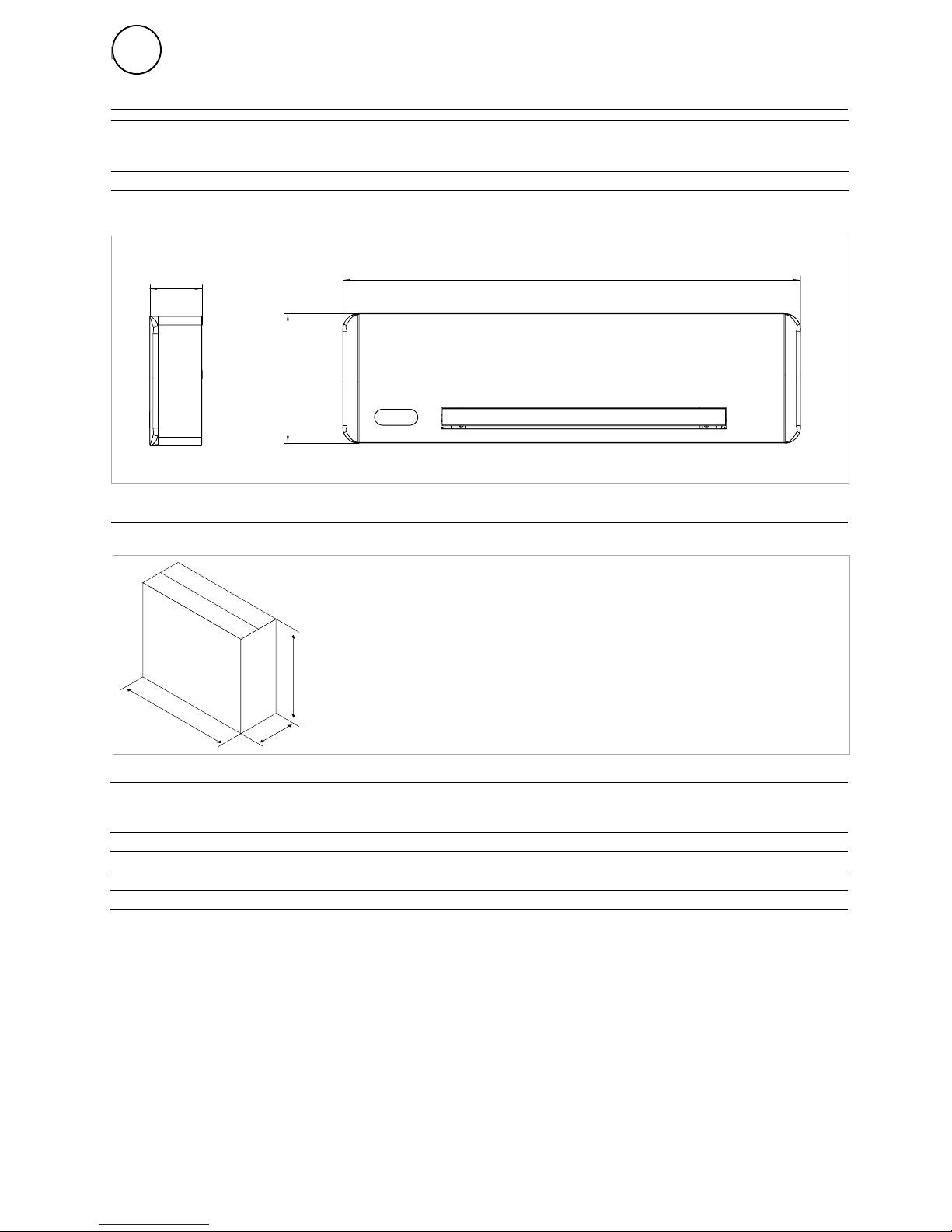
128
L
318
L
D
H
SLW
31
GENERAL
1.5 Dimensions SLW - 2 tubes
1.6 Transport dimensions and weight
SLW400
SLW600 SLW800
Weight
kg 15 17 20
Length (L)
mm 1035 1235 1435
Height (H)
mm 490 490 490
Depth (D)
mm 213 213 213
SLW400
SLW600 SLW800
Length (L)
mm 902 110 2 1302
GB
SIU
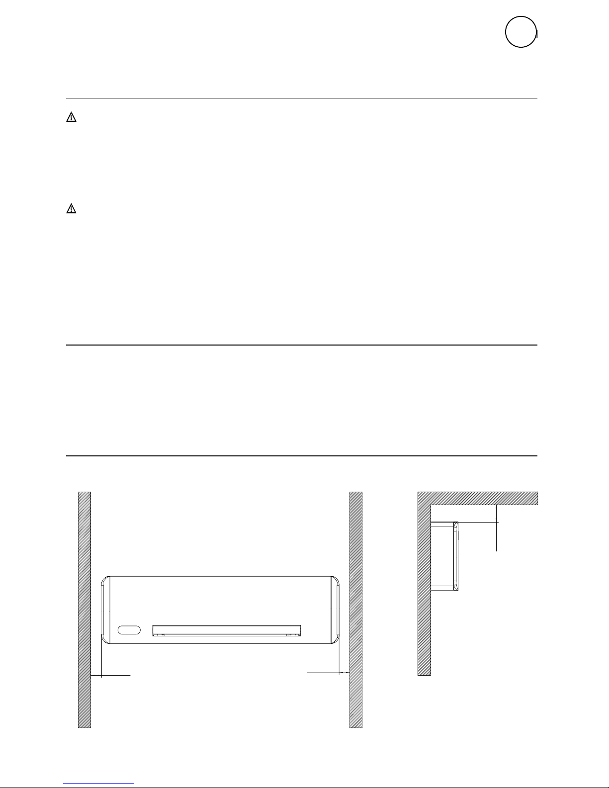
20 mm
20 mm
120 mm
SLW
32
INSTALLATION
2 Installation
Do not install the unit near:
• places directly exposed to the sun's rays
• sources of heat
• humid environments and areas in possible contact with water
• environments with oil mist
• environments subject to high frequencies
Ensure that:
• the wall on which the unit will be installed has a suitable structure and capacity
• the area of the interested wall is not affected by tubes or electrical lines
• the interested wall is perfectly flat
• there is an area free of obstacles that may otherwise eventually compromise the
circulation of the incoming and outgoing air
• the installation wall is preferably an external perimeter wall to allow external
condensate drainage
• the flow of air is not aimed directly towards persons
The following descriptions of the various phases of assembly and relative drawings refer to a
machine version with couplings on the right-hand side.
To ensure successful installation and optimal performance, carefully follow the instructions
in this manual. Failure to apply the specified standards, which may subsequently cause the
malfunctioning of the equipment, shall release Frico from any warranty obligations and from
any responsibility for eventual damage caused to persons, animals or things.
The figure indicates the minimum distances from the wall and room furniture for the
assembly of the fan coil unit
2.1 Positioning the unit
2.2 Installation method
2.3 Minimum installation distances
GB
SIU
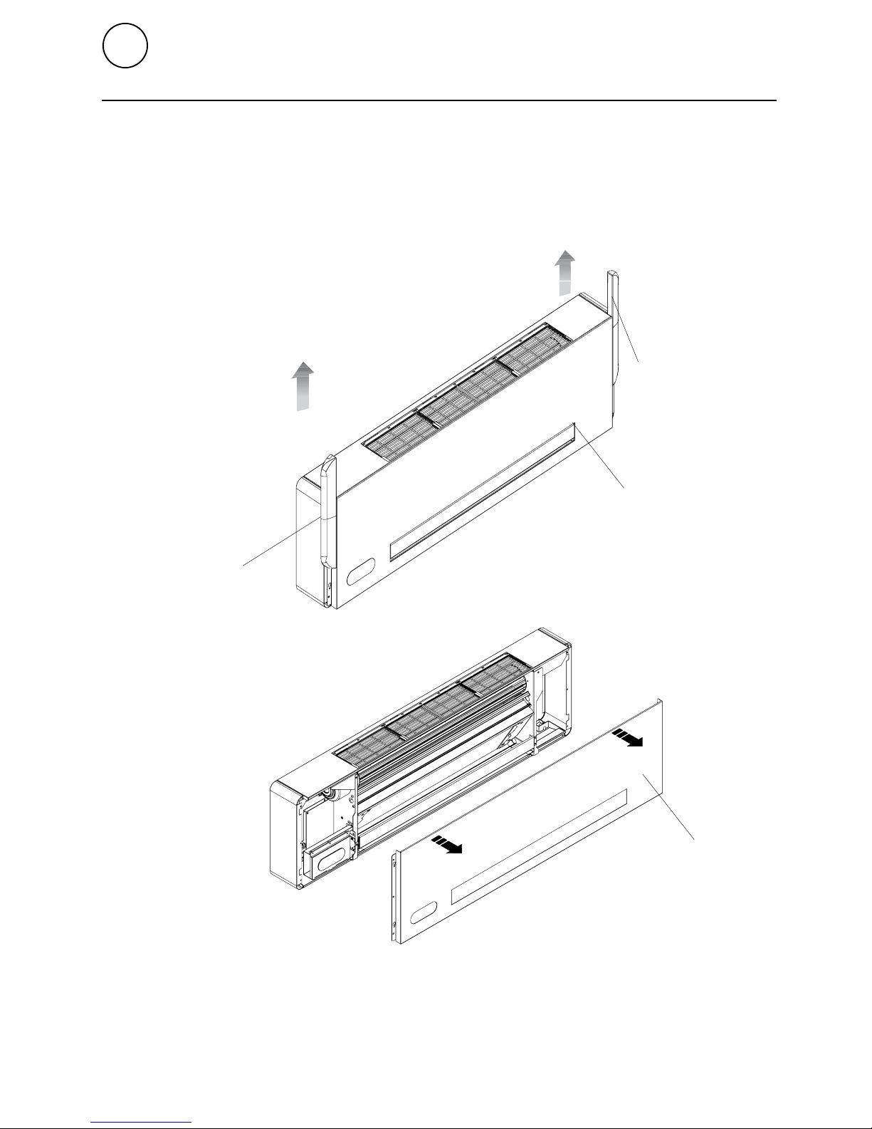
A
B
B
A
A Side panels
B Front visible panel
SLW
33
INSTALLATION
• Remove the side panels by sliding them upwards as shown in the figure below
• Remove the 6 hex head screws on the sides of the front panel
• Remove the front visible panel as shown in the figure
2.4 Opening visible parts for installation of unit
GB
SIU
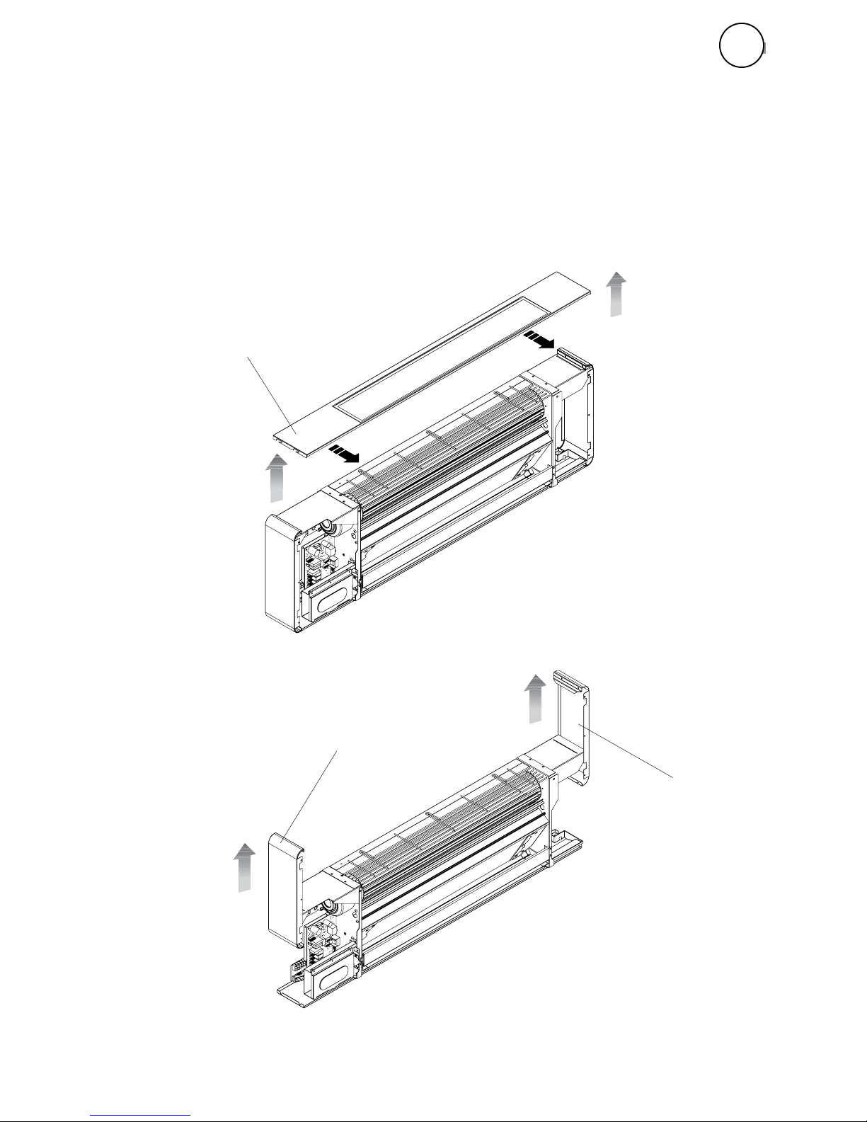
B
A
B
A Upper grill
B Side panels
SLW
34
INSTALLATION
• Remove the upper grill, pulling it towards yourself and lifting it upwards as shown in the
figure
• Remove the side panels by lifting them upwards
GB
 Loading...