

Page 1
.... 81
RU
.... 53
IT
.... 46
ES
.... 60
NL
.... 67
NO
.... 74
PL
.... 25
GB
.... 18
SE
.... 32
DE
.... 39
FR
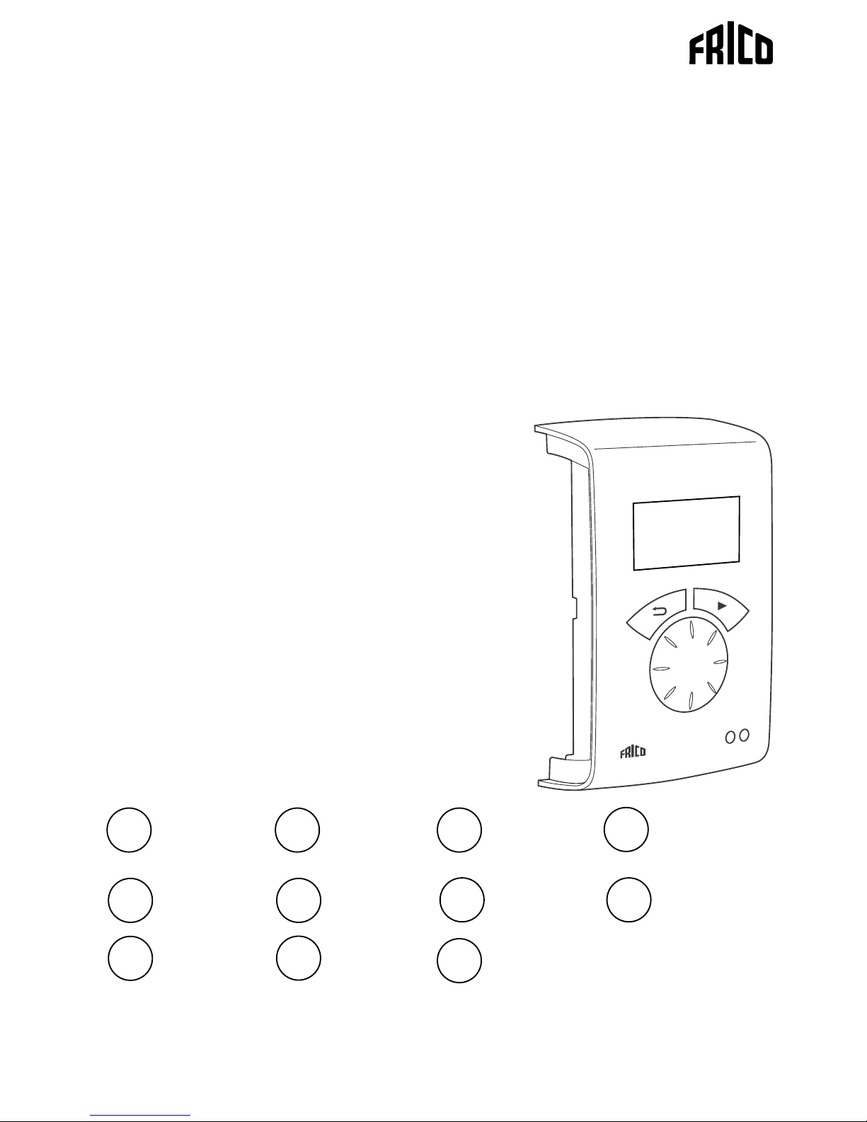
SIRe Competent
Quick guide
SIRe AC
SIRe FC
Original instructions
.... 89
FI
Page 2
SIRe Competent
2
7 8
9
10
11
12
15 16
17
18
19 20
COM 1 COM 2
ROOM
C2
X5
C1
X4
ROOM
X3
Pot.
Unit ID
ACTUATOR
SUPPLY
N L
N
L
PE
L
~
230V~
C2
X5
C1
X4
ROOM
X3
Pot.
Unit ID
ACTUATOR
SUPPLY
N L
N
L
PE
L
~
230V~
C2
X5
C1
X4
ROOM
X3
Pot.
Unit ID
ACTUATOR
SUPPLY
N L
N
L
PE
L
~
230V~
+-
C
NC
SIReDC
SIReRTX
(optional)
SIReC1X
SIReCC6XX (max 10 m)
SIReB1/B2/B1EC
SIReB1/B2/B1EC
SIReB1/B2/B1EC
SIReCC6XX
(max 50 m)
SIReCC6XX
(max 50 m)
SIReCC6XX
(max 50 m)
SIReCC4XX
(max 20 m)
BUS
SD230
SD230
SD230
L=1,5m
L=2m
SIReUA1 SIReC1X
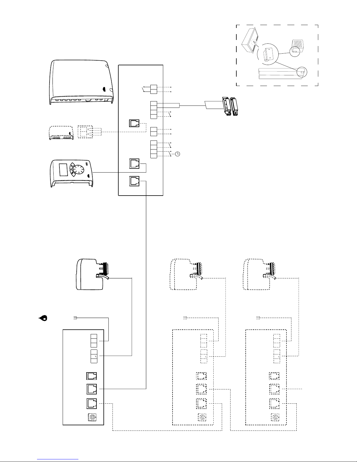
Wiring diagram - Competent
SIReAC/SIRe FC
SIReB1/B2/B1EC
*
*) SIReAC
Page 3
SIRe Competent
3
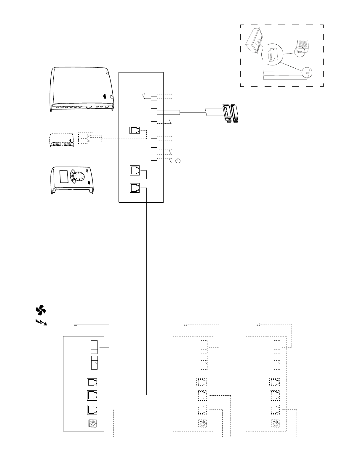
Wiring diagram - Competent
SIReAC/SIRe FC
SIReB1/B2/B1EC
7 8
9
10
11
12
15 16
17
18
19 20
COM 1 COM 2
ROOM
C2
X5
C1
X4
ROOM
X3
Pot.
Unit ID
ACTUATOR
SUPPLY
N L
N
L
PE
L
~
230V~
C2
X5
C1
X4
ROOM
X3
Pot.
Unit ID
ACTUATOR
SUPPLY
N L
N
L
PE
L
~
230V~
C2
X5
C1
X4
ROOM
X3
Pot.
Unit ID
ACTUATOR
SUPPLY
N L
N
L
PE
L
~
230V~
+-
C
NC
SIReUA1 SIReC1X
SIReDC
SIReRTX
(optional)
SIReC1X
SIReCC6XX (max 10 m)
SIReB1/B2/B1EC
SIReB1/B2/B1EC
SIReB1/B2/B1EC
SIReCC6XX
(max 50 m)
SIReCC6XX
(max 50 m)
SIReCC6XX
(max 50 m)
SIReCC4XX
(max 20 m)
BUS
L=2m
*
*) SIReAC
Page 4
4
1
SE
GB
Wiring diagram - Advanced
SIRe B1/B2/B1EC
2
Page 5

5
!
=
=
OK
OK
4
3a
Wiring diagram - Advanced
8
7
0
1
2
3
4
5
6
9
!
3b
=
1
0
OK
Page 6
6
5
?
www.frico.se
Svenska Polski
Norsk
Русский
English English
Deutsch Čeština
Français Slovenčina
Italiano Türkçe
Español Português
Nederlands Română
Suomi Magyar
Dansk Українська
UA1Y UA1Z
Page 7
SIRe Competent
7
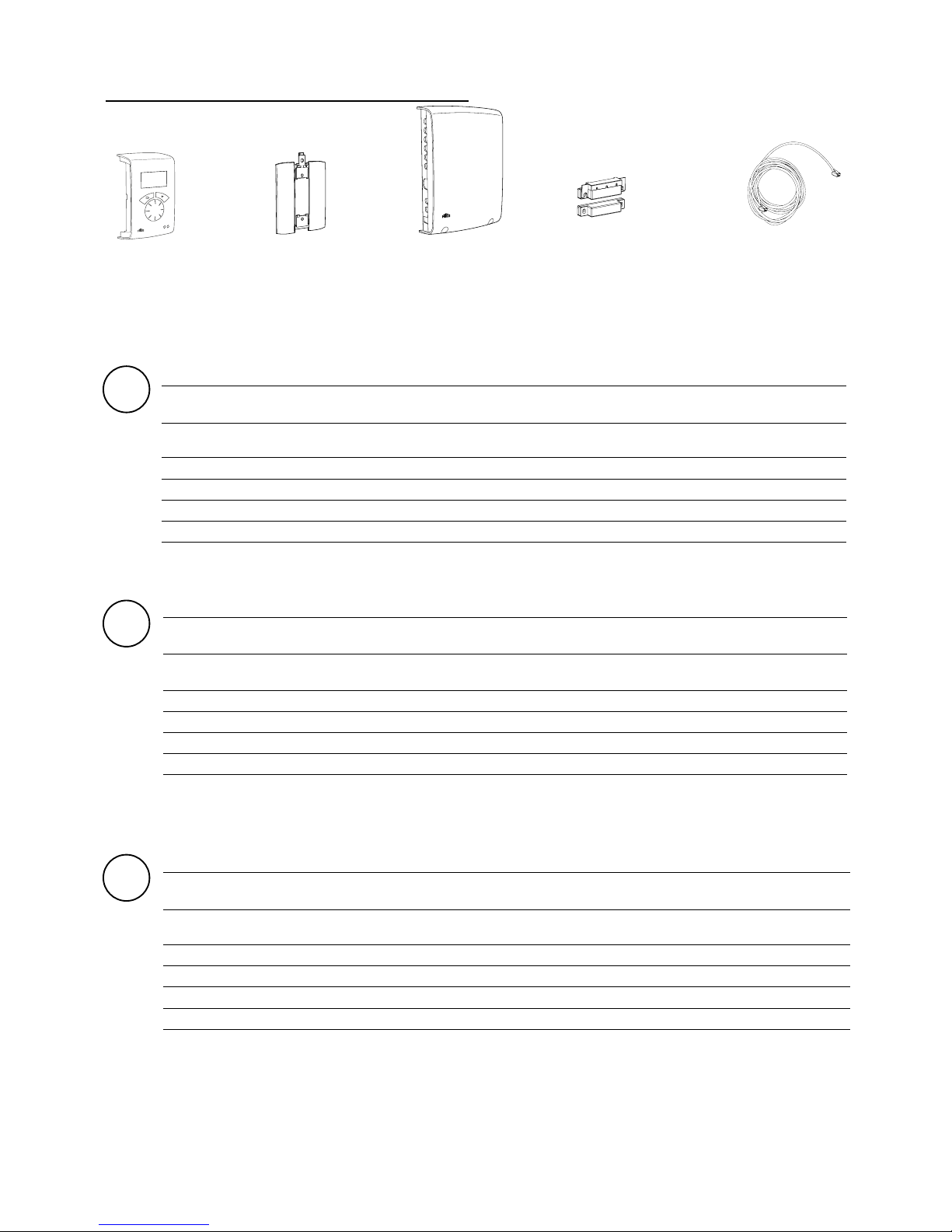
Constituent parts
Type Description HxWxD
[mm]
L
[m]
SIReUA1
Control unit, with internal room sensor, Wall unit
cover
120x70x35
SIReC1X PC Board HUB Competent 202x139x50
SIReDC Magnetic door contact
SIReCC603 Modular cable RJ12 (6/6) 3
SIReCC605 Modular cable RJ12 (6/6) 5
GB
Ty p Beschreibung HxBxT
[mm]
L
[m]
SIReUA1
Kontrolleinheit, mit Innenraumfühler, WandgerätAbdeckung
120x70x35
SIReC1X Steuerkarte HUB Competent 202x139x50
SIReDC Magnetischer Türkontakt
SIReCC603 Modulares Kabel RJ12 (6/6) 3
SIReCC605 Modulares Kabel RJ12 (6/6) 5
Bestandteile
DE
SIReAC SIReFC
+
SIReUA1 SIReC1X SIReDC
(SIReAC)
SIReCC
SE
Ty p Beskrivning HxBxD
[mm]
L
[m]
SIReUA1
Kontrollenhet, med inbyggd rumssensor,
Dostäckarlock
120x70x35
SIReC1X Styrkort HUB Competent 202x139x50
SIReDC Magnetisk dörrkontakt
SIReCC603 Modularkabel RJ12 (6/6) 3
SIReCC605 Modularkabel RJ12 (6/6) 5
Beståndsdelar
Page 8
SIRe Competent
8
Ty p Omschrijving HxWxD
[mm]
L
[m]
SIReUA1
Regelunit, met interne kamersensor, kap
wandgemonteerde unit
120x70x35
SIReC1X Hub printplaat competent 202x139x50
SIReDC Deurcontact
SIReCC603 Modulaire kabel Rj12 (6/6) 3
SIReCC605 Modulaire kabelRj12 (6/6) 5
Onderdelen
NL
Type Désignation HxLxP
[mm]
L
[m]
SIReUA1
Unité de contrôleavec sonde d'ambiance interne,
protection de boîtier mural.
120x70x35
SIReC1X Carte électronique HUB Competent 202x139x50
SIReDC Contact de position magnétique
SIReCC603 Câble modulaire RJ12 (6/6) 3
SIReCC605 Câble modulaire RJ12 (6/6) 5
Pièces constitutives
FR
Tipo Descripción HxWxD
[mm]
L
[m]
SIReUA1
Unidad de control, Con sensor de ambiente interno,
Tapa para unidad de pared
120x70x35
SIReC1X Tarjeta hub pc competent 202x139x50
SIReDC Contacto de puerta
SIReCC603 Cable modular Rj12 (6/6) 3
SIReCC605 Cable modular Rj12 (6/6) 5
Componentes
ES
Tipo Descrizione HxLxP
[mm]
L
[m]
SIReUA1
Unità di controllo, con sensore interno della
temperatura ambiente, copertura per unità a parete
120x70x35
SIReC1X
HUB scheda PC Competent
202x139x50
SIReDC
Contatto magnetica per porta
SIReCC603
Cavo modulare RJ12 (6/6)
3
SIReCC605
Cavo modulare RJ12 (6/6)
5
Componenti
IT
Page 9
SIRe Competent
9
Type Beskrivelse HxBxD
[mm]
L
[m]
SIReUA1
Kontrollenhet, med intern romføler, deksel til
veggenhet
120x70x35
SIReC1X PC Board HUB Competent 202x139x50
SIReDC Dørkontakt
SIReCC603 Modulærkabel RJ12 (6/6) 3
SIReCC605 Modulærkabel RJ12 (6/6) 5
Bestanddeler
NO
Ty p Opis HxWxD
[mm]
L
[m]
SIReUA1
Sterownik z wewnętrznym czujnikiem temperatury
pomieszczenia i pokrywą naścienną
120x70x35
SIReC1X Karta PC HUB Competent 202x139x50
SIReDC Czujnik drzwiowy
SIReCC603 Kabel modułowy Rj12 (6/6) 3
SIReCC605 Kabel modułowy Rj12 (6/6) 5
Części składowe
PL
Модель Описание Габариты
[мм]
L
[м]
SIReUA1
Панель управления, с датчиком комнатной
температуры , с накладкой на стену
120x70x35
SIReC1X
Управляющая плата системы Профи
202x139x50
SIReDC
Дверной Контакт
SIReCC603
Кабель С Разъемами RJ12 (6/6)
3
SIReCC605
Кабель С Разъемами RJ12 (6/6)
5
Комплектующие элементы
RU
Malli Kuvaus KxLxS
[mm]
P
[m]
SIReUA1 Ohjausyksikkö sisäisellä huoneanturilla, pinta-asennus 120x70x35
SIReC1X Piirikortti HUB Competent 202x139x50
SIReDC Ovikosketin
SIReCC603 Modulaarikaapeli RJ12 (6/6) 3
SIReCC605 Modulaarikaapeli RJ12 (6/6) 5
Osat
FI
Page 10
SIRe Competent
10
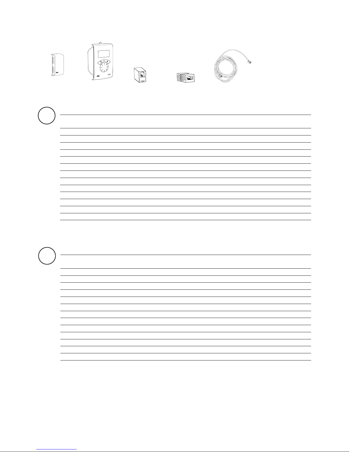
SIReRTX
SIReUR
SIReCJ4
SIReCJ6
SIReCC
Ty p RSK-nr E-nr Beskrivning HxBxD
[mm]
L
[m]
SIReRTX 673 09 22 87 510 12 Extern rumstemperaturgivare 70x33x23 10
SIReUR* 673 09 21 87 510 11 Kit för infällt montage 114x70x50
SIReCJ4 673 09 70 87 510 33 Skarvstycke för två st. RJ11 (4/4)
SIReCJ6 673 09 71 87 510 34 Skarvstycke för två st. RJ12 (6/6)
SIReCC603 673 09 23 87 510 13 Modularkabel RJ12 (6/6) 3
SIReCC605 673 09 24 87 510 14 Modularkabel RJ12 (6/6) 5
SIReCC610 673 09 25 87 510 15 Modularkabel RJ12 (6/6) 10
SIReCC615 673 09 26 87 510 16 Modularkabel RJ12 (6/6) 15
SIReCC640 673 18 79 87 510 45 Modularkabel RJ12 (6/6) 40
SIReCC403 673 09 27 87 510 17 Modularkabel RJ11 (4/4) 3
SIReCC405 673 09 28 87 510 18 Modularkabel RJ11 (4/4) 5
SIReCC410 673 09 29 87 510 19 Modularkabel RJ11 (4/4) 10
SIReCC415 673 09 30 87 510 20 Modularkabel RJ11 (4/4) 15
SE
Tillval
*) Se separat manual.
GB
Type Description HxWxD
[mm]
L
[m]
SIReRTX External room temperature sensor 70x33x23 10
SIReUR* Kit for recessed installation 114x70x50
SIReCJ4 Joint piece for two pcs. RJ11 (4/4)
SIReCJ6 Joint piece for two pcs. RJ12 (6/6)
SIReCC603 Modular cable RJ12 (6/6) 3
SIReCC605 Modular cable RJ12 (6/6) 5
SIReCC610 Modular cable RJ12 (6/6) 10
SIReCC615 Modular cable RJ12 (6/6) 15
SIReCC640 Modular cable RJ12 (6/6) 40
SIReCC403 Modular cable RJ11 (4/4) 3
SIReCC405 Modular cable RJ11 (4/4) 5
SIReCC410 Modular cable RJ11 (4/4) 10
SIReCC415 Modular cable RJ11 (4/4) 15
Option
*) See separate manual.
Page 11
SIRe Competent
11
DE
Ty p Beschreibung HxBxT
[mm]
L
[m]
SIReRTX Externer Raumtemperatursensor 70x33x23 10
SIReUR* Kit für versenkte Installation 114x70x50
SIReCJ4 Verbindungsstück für zwei Teile RJ11 (4/4)
SIReCJ6 Verbindungsstück für zwei Teile RJ12 (6/6)
SIReCC603 Modulares Kabel RJ12 (6/6) 3
SIReCC605 Modulares Kabel RJ12 (6/6) 5
SIReCC610 Modulares Kabel RJ12 (6/6) 10
SIReCC615 Modulares Kabel RJ12 (6/6) 15
SIReCC640 Modulares Kabel RJ12 (6/6) 40
SIReCC403 Modulares Kabel RJ11 (4/4) 3
SIReCC405 Modulares Kabel RJ11 (4/4) 5
SIReCC410 Modulares Kabel RJ11 (4/4) 10
SIReCC415 Modulares Kabel RJ11 (4/4) 15
Optional
*) Siehe separates Handbuch.
FR
Type Désignation HxLxP
[mm]
L
[m]
SIReRTX Sonde de température ambiante déportée 70x33x23 10
SIReUR* Kit pour installation encastrée 114x70x50
SIReCJ4 Pièce de jonction pour deux pcs. RJ11 (4/4)
SIReCJ6 Pièce de jonction pour deux pcs. RJ12 (6/6)
SIReCC603 Câble modulaire RJ12 (6/6) 3
SIReCC605 Câble modulaire RJ12 (6/6) 5
SIReCC610 Câble modulaire RJ12 (6/6) 10
SIReCC615 Câble modulaire RJ12 (6/6) 15
SIReCC640 Câble modulaire RJ12 (6/6) 40
SIReCC403 Câble modulaire RJ11 (4/4) 3
SIReCC405 Câble modulaire RJ11 (4/4) 5
SIReCC410 Câble modulaire RJ11 (4/4) 10
SIReCC415 Câble modulaire RJ11 (4/4) 15
Option
*) Consultez le manuel associé.
ES
Tipo L
[m]
HxWxD
[mm]
L
[m]
SIReRTX Sensor de temperatura ambiente externo 70x33x23 10
SIReUR* Kit para instalación empotrada 114x70x50
SIReCJ4 Pieza de unión RJ11 (4/4)
SIReCJ6 Pieza de unión RJ12 (6/6)
SIReCC603 Cable modular RJ12 (6/6) 3
SIReCC605 Cable modular RJ12 (6/6) 5
SIReCC610 Cable modular RJ12 (6/6) 10
SIReCC615 Cable modular RJ12 (6/6) 15
SIReCC640 Cable modular RJ12 (6/6) 40
SIReCC403 Cable modular RJ11 (4/4) 3
SIReCC405 Cable modular RJ11 (4/4) 5
SIReCC410 Cable modular RJ11 (4/4) 10
SIReCC415 Cable modular RJ11 (4/4) 15
Opciones
*) Consulte el manual correspondiente.
Page 12
SIRe Competent
12
IT
Tipo Descrizione HxLxP
[mm]
L
[m]
SIReRTX Sensore esterno della temperatura ambiente 70x33x23 10
SIReUR* Kit per installazione incassata 114x70x50
SIReCJ4 Elemento di giunzione RJ11 (4/4)
SIReCJ6 Elemento di giunzione RJ12 (6/6)
SIReCC603 Cavo modulare RJ12 (6/6) 3
SIReCC605 Cavo modulare RJ12 (6/6) 5
SIReCC610 Cavo modulare RJ12 (6/6) 10
SIReCC615 Cavo modulare RJ12 (6/6) 15
SIReCC640 Cavo modulare RJ12 (6/6) 40
SIReCC403 Cavo modulare RJ11(4/4) 3
SIReCC405 Cavo modulare RJ11(4/4) 5
SIReCC410 Cavo modulare RJ11 (4/4) 10
SIReCC415 Cavo modulare RJ11(4/4) 15
Opzione
*) Vedere il manuale specifico.
NL
Ty p Omschrijving HxWxD
[mm]
L
[m]
SIReRTX External room temperature sensor 70x33x23 10
SIReUR* Kit for recessed installation 114x70x50
SIReCJ4 Koppelstuk voor twee stuks RJ11 (4/4)
SIReCJ6 Koppelstuk voor twee stuks RJ12 (6/6)
SIReCC603 Modulaire kabel RJ12 (6/6) 3
SIReCC605 Modulaire kabel RJ12 (6/6) 5
SIReCC610 Modulaire kabel RJ12 (6/6) 10
SIReCC615 Modulaire kabel RJ12 (6/6) 15
SIReCC640 Modulaire kabel RJ12 (6/6) 40
SIReCC403 Modulaire kabel RJ11 (4/4) 3
SIReCC405 Modulaire kabel RJ11 (4/4) 5
SIReCC410 Modulaire kabel RJ11 (4/4) 10
SIReCC415 Modulaire kabel RJ11 (4/4) 15
Optie
*) Zie aparte handleiding.
NO
Type NRF-no. EL-no. Beskrivelse HxBxD
[mm]
L
[m]
SIReRTX 85 022 94 54 910 01
Ekstern
romtemperaturføler
70x33x23 10
SIReUR* 85 022 93 49 325 00 Sett for innfelt montering 114x70x50
SIReCJ4 54 910 02 Skjøtestykke RJ11 (4/4)
SIReCJ6 Skjøtestykke RJ12 (6/6)
SIReCC603 85 022 95 54 329 01 Modulærkabel RJ12 (6/6) 3
SIReCC605 85 022 96 54 329 02 Modulærkabel RJ12 (6/6) 5
SIReCC610 85 022 97 54 329 03 Modulærkabel RJ12 (6/6) 10
SIReCC615 85 022 98 54 329 04 Modulærkabel RJ12 (6/6) 15
SIReCC640 Modulærkabel RJ12 (6/6) 40
SIReCC403 85 022 99 54 329 05 Modulærkabel RJ11 (4/4) 3
SIReCC405 85 023 01 54 329 06 Modulærkabel RJ11 (4/4) 5
SIReCC410 85 023 02 54 329 07 Modulærkabel RJ11 (4/4) 10
SIReCC415 85 023 03 54 329 08 Modulærkabel RJ11 (4/4) 15
Ekstrautstyr
*) Se egen håndbok.
Page 13
SIRe Competent
13
Malli Kuvaus KxLxS
[mm]
P
[m]
SIReRTX Ulkoinen huonelämpötila-anturi 70x33x23 10
SIReUR* Uppoasennussarja 114x70x50
SIReCJ4 Jatkoliitin 2xRJ11(4/4)
SIReCJ6 Jatkoliitin 2xRJ11(4/4)
SIReCC603 Modulaarikaapeli RJ12 (6/6) 3
SIReCC605 Modulaarikaapeli RJ12 (6/6) 5
SIReCC610 Modulaarikaapeli RJ12 (6/6) 10
SIReCC615 Modulaarikaapeli RJ12 (6/6) 15
SIReCC640 Modulaarikaapeli RJ12 (6/6) 40
SIReCC403 Modulaarikaapeli RJ11 (4/4) 3
SIReCC405 Modulaarikaapeli RJ11 (4/4) 5
SIReCC410 Modulaarikaapeli RJ11 (4/4) 10
SIReCC415 Modulaarikaapeli RJ11 (4/4) 15
FI
Vaihtoehdot
*) Katso erillinen käyttöohje.
PL
Typ Opis HxWxD
[mm]
L
[m]
SIReRTX
Zewnętrzny czujnik temperatury pomieszczenia 70x33x23 10
SIReUR* Zestaw do zabudowy 114x70x50
SIReCJ4 Połączenie. RJ11 (4/4)
SIReCJ6 Połączenie. RJ12 (6/6)
SIReCC603 Kabel modułowy RJ12 (6/6) 3
SIReCC605
Kabel modułowy
RJ12 (6/6)
5
SIReCC610 Kabel modułowy RJ12 (6/6) 10
SIReCC615 Kabel modułowy RJ12 (6/6) 15
SIReCC640 Kabel modułowy RJ12 (6/6) 40
SIReCC403 Kabel modułowy RJ11 (4/4) 3
SIReCC405 Kabel modułowy RJ11 (4/4) 5
SIReCC410 Kabel modułowy RJ11 (4/4) 10
SIReCC415 Kabel modułowy RJ11 (4/4) 15
Opcja
*) Patrz oddzielna instrukcja.
RU
Модель Описание Габариты
[мм]
L
[м]
SIReRTX
Внешний датчик комнатной температуры
70x33x23 10
SIReUR*
Блок управления для установки в стену
114x70x50
SIReCJ4
Разъем RJ11 (4/4)
SIReCJ6
Разъем RJ12 (6/6)
SIReCC603
Кабель с разъемами RJ12 (6/6)
3
SIReCC605
Кабель с разъемами RJ12 (6/6)
5
SIReCC610
Кабель с разъемами RJ12 (6/6)
10
SIReCC615
Кабель с разъемами RJ12 (6/6)
15
SIReCC640
Кабель с разъемами RJ12 (6/6)
40
SIReCC403
Кабель с разъемами RJ11 (4/4)
3
SIReCC405
Кабель с разъемами RJ11 (4/4)
5
SIReCC410
Кабель с разъемами RJ11 (4/4)
10
SIReCC415
Кабель с разъемами RJ11 (4/4)
15
*) См. отдельную инструкцию.
Принадлежности
Page 14
SIRe Competent
14
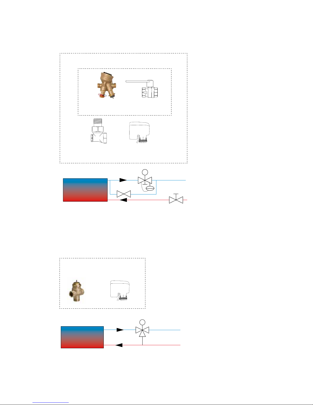
SD230
TRVS
SD230TRVS
VOT
SD230
TAC
AV
BPV10
SD230BPV10
AVTAC
VKF
VLSP
Page 15
SIRe Competent
15
SE
Ty p RSK-nr Komponenter Anslutning
VLSP15LF 670 45 35 VKF15LF + SD230 + BPV10 DN15
VLSP15NF 670 45 36 VKF15NF + SD230 + BPV10 DN15
VLSP20 670 45 37 VKF20 + SD230 + BPV10 DN20
VLSP25 670 45 38 VKF25 + SD230 + BPV10 DN25
VLSP32 670 45 39 VKF32 + SD230 + BPV10 DN32
Vattenreglering - ventilpaket*
*) Se separata manualer.
GB
Water control - valve system*
*) See separate manuals.
Type Description Connection
VLSP15LF Pressure independent DN15
VLSP15NF Pressure independent DN15
VLSP20 Pressure independent DN20
VLSP25 Pressure independent DN25
VLSP32 Pressure independent DN32
VOT15 Three way valve and actuator on/off DN15
VOT20 Three way valve and actuator on/off DN20
VOT25 Three way valve and actuator on/off DN25
DE
Wasserregelung - Ventilsystem*
*) siehe separates Handbuch.
Ty p Beschreibung Anschluss
VLSP15LF Druckunabhängig DN15
VLSP15NF Druckunabhängig DN15
VLSP20 Druckunabhängig DN20
VLSP25 Druckunabhängig DN25
VLSP32 Druckunabhängig DN32
VOT15 3-Wege-Regelventil mit Stellmotor, Ein/Aus DN15
VOT20 3-Wege-Regelventil mit Stellmotor, Ein/Aus DN20
VOT25 3-Wege-Regelventil mit Stellmotor, Ein/Aus DN25
FR
Régulation hydraulique - système de vannes*
*) Consultez les manuels associés.
Type Désignation Raccordement
VLSP15LF Indépendant de la pression DN15
VLSP15NF Indépendant de la pression DN15
VLSP20 Indépendant de la pression DN20
VLSP25 Indépendant de la pression DN25
VLSP32 Indépendant de la pression DN32
VOT15 Vanne à trois voies DN15
VOT20 Vanne à trois voies DN20
VOT25 Vanne à trois voies DN25
Page 16
SIRe Competent
16
NL
Waterregeling - kleppensysteem*
*) Zie aparte handleidingen
Type Omschrijving Aansluiting
VLSP15LF Drukonafhankelijke DN15
VLSP15NF Drukonafhankelijke DN15
VLSP20 Drukonafhankelijke DN20
VLSP25
Drukonafhankelijke DN25
VLSP32 Drukonafhankelijke DN32
VOT15 Driewegventiel en magneetventiel aan/uit. DN15
VOT20 Driewegventiel en magneetventiel aan/uit. DN20
VOT25 Driewegventiel en magneetventiel aan/uit. DN25
NO
Vannregulering - ventilsystem*
*) Se egne håndbøker.
Type Beskrivelse Tilkobling
VLSP15LF Trykkuavhengig DN15
VLSP15NF Trykkuavhengig DN15
VLSP20 Trykkuavhengig DN20
VLSP25 Trykkuavhengig DN25
VLSP32 Trykkuavhengig DN32
VOT15 Treveisventil og regulator på/av DN15
VOT20 Treveisventil og regulator på/av DN20
VOT25 Treveisventil og regulator på/av DN25
ES
Control del agua - sistema de válvulas*
*) Consulte el manual correspondiente.
Tipo Descripción Conexión
VLSP15LF Independiente de la presión DN15
VLSP15NF Independiente de la presión DN15
VLSP20 Independiente de la presión DN20
VLSP25 Independiente de la presión DN25
VLSP32 Independiente de la presión DN32
VOT15 Válvula de 3 vías y actuador on/off DN15
VOT20 Válvula de 3 vías y actuador on/off DN20
VOT25 Válvula de 3 vías y actuador on/off DN25
IT
Controllo dell'acqua - sistema di valvole*
*) vedere i manuali specifici.
Tipo Descrizione Collegamento
VLSP15LF Indipendente dalla pressione DN15
VLSP15NF Indipendente dalla pressione DN15
VLSP20 Indipendente dalla pressione DN20
VLSP25 Indipendente dalla pressione DN25
VLSP32 Indipendente dalla pressione DN32
VOT15 Valvola a tre vie e attuatore aperto/chiuso DN15
VOT20 Valvola a tre vie e attuatore aperto/chiuso DN20
VOT25 Valvola a tre vie e attuatore aperto/chiuso DN25
Page 17
SIRe Competent
17
PL
Regulacja przepływu wody – zestaw zaworów*
*) Patrz oddzielne instrukcje.
Ty p Opis Podłączenie
VLSP15LF Zestaw zaworów, dwupołożeniowy, niezależny od ciśnienia DN15
VLSP15NF Zestaw zaworów, dwupołożeniowy, niezależny od ciśnienia DN15
VLSP20 Zestaw zaworów, dwupołożeniowy, niezależny od ciśnienia DN20
VLSP25 Zestaw zaworów, dwupołożeniowy, niezależny od ciśnienia DN25
VLSP32 Zestaw zaworów, dwupołożeniowy, niezależny od ciśnienia DN32
VOT15 3-drogowy zawór regulacyjny i siłownik dwupołożeniowy
DN15
VOT20 3-drogowy zawór regulacyjny i siłownik dwupołożeniowy
DN20
VOT25 3-drogowy zawór regulacyjny i siłownik dwupołożeniowy
DN25
RU
Регулировка расхода воды - комплект клапанов*
*) смотрите отдельную инструкцию.
Модель Описание Соединение
VLSP15LF
Комплект клапанов on/off с функцией пост. расхода
DN15
VLSP15NF
Комплект клапанов on/off с функцией пост. расхода
DN15
VLSP20
Комплект клапанов on/off с функцией пост. расхода
DN20
VLSP25
Комплект клапанов on/off с функцией пост. расхода
DN25
VLSP32
Комплект клапанов on/off с функцией пост. расхода
DN32
VOT15
3-х ходовой клапан и электропривод on/off DN15
VOT20
3-х ходовой клапан и электропривод on/off DN20
VOT25
3-х ходовой клапан и электропривод on/off DN25
Malli Kuvaus Kytkentä
VLSP15LF Painevakioitu venttiilisarja on/off DN15
VLSP15NF Painevakioitu venttiilisarja on/off DN15
VLSP20 Painevakioitu venttiilisarja on/off DN20
VLSP25 Painevakioitu venttiilisarja on/off DN25
VLSP32 Painevakioitu venttiilisarja on/off DN32
FI
Veden säätö - venttiilisarja*
*) Katso erillinen käyttöohje.
Page 18
SIRe Competent
25
GB
0
1
2
3
45
6
7
8
9
0
1
2
3
45
6
7
8
9
X5
C2
X4
C1
X3
ROOM
PE N L
SUPPLY 230V
ACTUATOR
230V
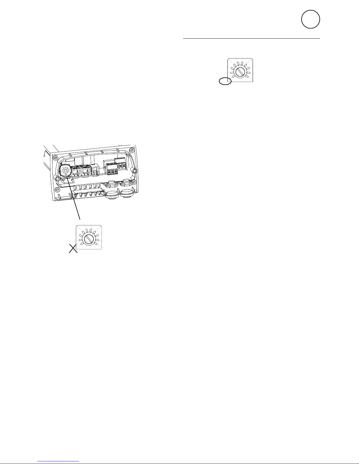
To run the unit
temporarily without
external control
select mode 0.
Each unit should have a
unique ID on its SIReB1/
B2/B1EC card.
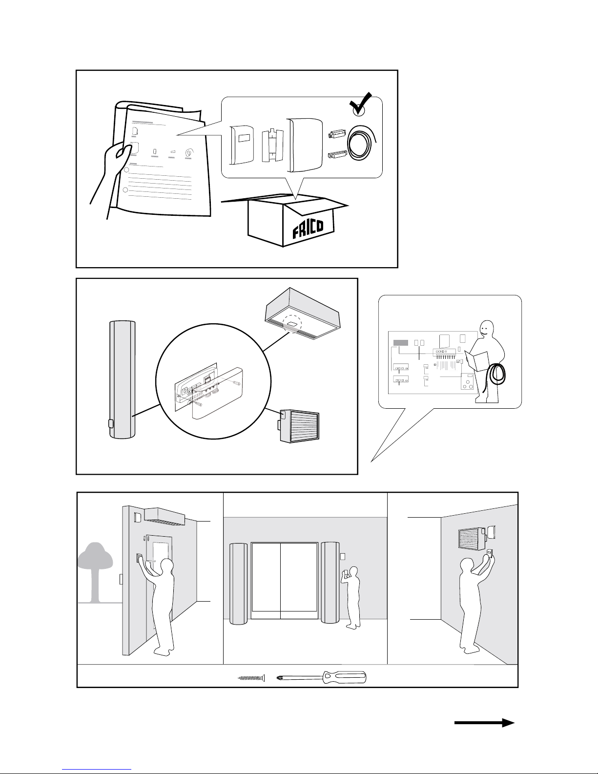
Quick guide/Start up
1. Check that all constituent parts are present
(see section Constituent parts).
2. Mount and connect all units and
components and where applicable
accessories (e.g. actuator), see wiring
diagram. When several units are connected
set a unique ID for each unit (1-9) which
is set in the ID selector of the SIReB1/B2/
B1EC.
Operation without control unit
3. Power up all units.
4. The start-up wizard runs and basic settings
are made. The system check identifies
connected components in the system and
the function test shows if all units are
correctly connected.
Page 19
SIRe Competent
26
GB
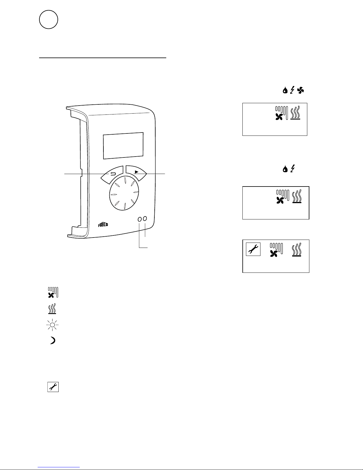
OFF
Fan speed step
Back
Forward/ Confirm
Alarm Red led
Run signal Green led
Heating step
Week program
Day
Week program
Night
Week program
Out of operation
Overview
Control unit SIReUA1
SIRe AC
SIRe FC
Air curtains
Fan heaters
19
IN
.0
°C
DOOR
CL
19
IN
.0
°C
19
.0
IN °C
Auto
Manual mode
Manual operation (SIReFC)
Page 20
SIRe Competent
27
GB
Support menu
The support menu is password protected and
is used for support in contact with Frico or
authorised installer.
General settings
Language, time, date, function test, manual
system check and factory reset.
Alarm and error codes
Current settings
Current set values.
Temperature settings
Day/night temperature. The night
temperature is only valid when the week
program is activated.
System on/off
Safety features are still active when the
system is switched off.
Installer menu
Password 1932
Installer status screen
Current settings and functions.
Week program
Activate week program, check, change, add or
erase program.
Fan settings
Fan control and over run functions.
Main menu
Complete manual see www.frico.se
Reset alarm
Note! Before resetting, check that the fault is rectified
and there is nothing to prevent the unit from being
recommissioned.
Press and select reset alarm.
At the first start up alarm and error codes
can occur, these will usually be reset without
actions.
Power failure
Note! A power loss longer than 7 days may
require an adjustment of time and date.
The week program is affected if the clock is
not correctly set.
Fan control
Maximum fan speed and fan speed when the
door is closed. Fan speed when the door is
closed is only valid when using SIReAC.
Filter guard settings
Activate filter timer and set service interval.
External control (BMS)
External on/off, fan control 0-10V. See
"Connecting external control".
Heating settings
Set point difference open door, (calibrating
sensors).
Summer/Winter
Summer - heat off
Page 21
SIRe Competent
28
GB
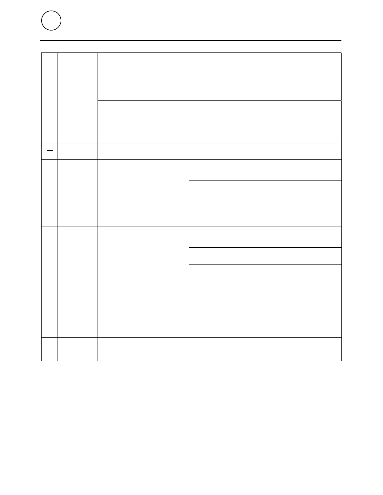
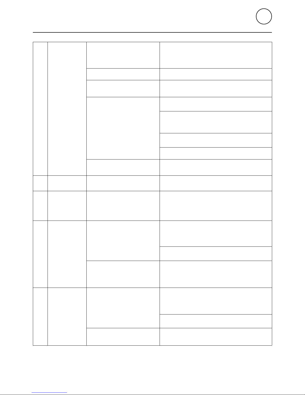
Table - Alarm
A1
A2
A3
A4
A5
Motor alarm
Over
heating
alarm
Check function of the contactors (E), Check function
of actuator and valve, flow temperature and bypass
settings (W).
Check internal temperature sensor, measure
resistance, 47kOhm at 25°C.
Frost
protection
alarm
The temperature in the unit
has fallen below the alarm
limit for frost protection (only
water heated units with internal
temperature sensor and/
or return water temperature
sensor SIReWTA).
Check the function of the actuator, valve and
bypass settings.
Check the temperature and flow of the hot water supply.
In event of an alarm there is a risk that the coil is
damaged, check carefully for leakage and replace
the water heating coil if damaged.
Filter alarm
Replace or clean the filter, if neccessary adjust the fixed
time based on how dirty the filter was and reset the alarm.
Replace or clean the filter, if neccessary adjust settings
of the filter guard based on how dirty the filter was and
reset the alarm.
Fixed run time before filter
alarm has been reached.
External alarm input (terminal
9-10) on SIReA1X/SIReC1X has
been activated
External
alarm
Check that nothing is obstructing the unit's air intake
and exhaust.
Check that nothing is obstructing the unit's air intake
and exhaust.
Check the external alarm.
Thermal contact has
deployed. One or more
motors are overheated.
When the overheated motor has cooled the thermal
switch shuts again and the alarm can be reset. At
repeated alarms, check the motors, replace damaged
motors.
Missing link on motor protection
on SIReB1/B2/B1EC.
For units having built-in thermal protection but without
external connection, the motor protection terminals must
be linked.
Check motor and transformer connection terminal on
the SIReB1/B2/B1EC-pc board.
The temperature in the unit
has exceeded the alarm limit
for overheating.
(Only units with internal
temperature sensor)
The external filter guard has been
activated.
Unit only starts on high speed.
For units having built-in thermal protection but
without external connection, the motor protection
terminals must be linked.
Cause
Action
Error code
Unit won't start.
Page 22
SIRe Competent
29
GB
E1
E2
E3
E4
E6
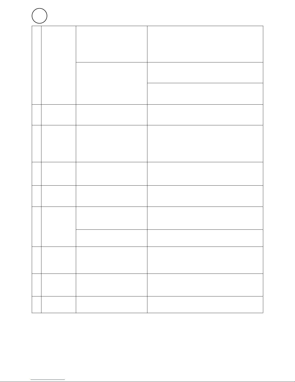
Communication
error
ID is set to 0 (Unit is running
continously).
Cables are not original.
Set an ID, run a Manual system check.
Make sure communication cables are correct (Frico
original cables has a circuit diagram indicating how
the contacts shall be crimped on to the cable.)
In multiple unit system, check that you have
230VAC to all units.
In Installer menu - Installer status screen, check that
all units ID are listed and that no extra units are listed.
When all units are powered up run a Manual system
check.
Disconnect power, set ID=0 and reconnect
power to test the B1/B2/B1EC pc-board.
Hardware failure - replace the SIReB1/B2/B1EC
pc-board. Contact Frico technical support.
Visual damage to SIReB1/B2/
B1EC.
Two or more SIReB1/B2/B1EC
have the same ID.
Try to reset the alarm. Make sure all units have
different ID-settings and perform a Manual system
check.
Program
error (No
program)
Try to reset the alarm. Disconnect power, set ID=0
and reconnect power to test the B1/B2/B1EC pcboard - result? If the unit is running act as if it was an
E1 Communication error. If it is not running, contact
Frico technical support.
Room
sensor error
Wrong temperature is displayed
in SIReUA1.
Try to reset the alarm. Check connections and
cable. False errors can occur in conjunction with
communication error, check that all other alarms
have been reset. Measure resistance, 47kOhm at
25°C.
If the sensor intentionally has been removed, run a
Manual system check to exclude it from the system.
If a return water sensor (SIReWTA) is connected
but not activated, the system will interpret that
value as a room temperature value, activate return
water sensor. When SIReWTA is used, SIReRTX
shall be connected to the SIReA1X.
Fault on or missing Return
water sensor SIReWTA
connected to SIReB1/B2/B1EC.
Return water temperature sensor is activated with
a SIReRTX-sensor connected - In the menu, disable
return water temperature sensor.
SIReB1/B2/B1EC (internal pcboard) do not communicate.
Try to reset the alarm. Check connections and
cable. False errors can occur in conjunction with
communication error, check that all other alarms
have been reset. Measure resistance, 47kOhm at
25°C.
If the sensor intentionally has been removed, run a
Manual system check to exclude it from the system.
Wrong temperature is
displayed in SIReUA1.
Return water
temp. sensor
error.
The unit won't start.
Perform a factory reset and reboot the system
(disconnect/ reconnect power).
One or more SIReB1/B2/B1EC do
not have program.
ID Error
Fault on or missing external
room sensor SIReRTX
connected to SIReB1/B2/
B1EC.
Error code Cause Action
Table - Error codes
Try to reset the alarm. Check connections,
modular cables and terminals, between all units
and components. Systematically shift position of
communication cables to identify a broken terminal
or cables.
Page 23
SIRe Competent
30
GB
E7
E8
E10
E12
E14
E20
E21
E22
E23
Fault on or missing,
mandatory Return water
sensor SIReWTA connected to
SIReB1/B2/B1EC.
Try to reset the alarm. Check connections and
cable. False errors can occur in conjunction
with communication error, check that all other
alarms have been reset. Measure resistance,
47kOhm at 25°C.
Confirm that WTA is connected to the SIReB1/
B2/B1EC and securely fastened to the return
water pipe and compare with what the actual
temperature is.
SIReRTX-sensor must not be connected to SIReB1/B2/
B1EC when the intention is to use return water sensor.
When SIReWTA is used, SIReRTX shall be connected to
the SIReA1X
Fault on or missing internal
temperature sensor, SIReIT,
connected to SIReB1/B2/B1EC.
Program error
(different
programs)
Two or more SIReB1/B2/B1EC
in the system have different
programs.
Outdoor
sensor
error
Fault on or missing external
room sensor, SIReRTX
connected to SIReA1X/C1X.
Fault on or missing, mandatory
outdoor temperature sensor,
SIReOTX, connected to SIReA1X.
SIReA1X/C1X (external pc-board)
do not communicate.
Try to reset the alarm. Check connections, modular
cables and terminals, between all units and components.
Systematically shift position of communication cables to
identify a broken terminal or cables.
Fault on internal room temperature
sensor in SIReUA1.
Try to reset the alarm. Check connections and
cable. False errors can occur in conjunction with
communication error, check that all other alarms have
been reset. If the error is not rectified SIReUA1 must be
replaced.
Multiple
control
units
connected
Try to reset the alarm. The system will only support
one control unit, disconnect and reset alarm.
Firmware
error
Components of different releases
are used in the system.
Make sure all units are from the same release, contact
Frico technical support.
Wrong temperature is
displayed in SIReUA1.
Internal
sensor Error
Room
sensor
error
Room
sensor
error
Communication
error
Cables are not original.
Logging tool or an extra control
unit SIReUA1 is connected to the
system.
Make sure communication cables are correct (Frico
original cables has a circuit diagram indicating how the
contacts shall be crimped on to the cable.)
Try to reset the alarm. Check connections and
cable. False errors can occur in conjunction with
communication error, check that all other alarms have
been reset. Measure resistance, 47kOhm at 25°C.
Try to reset the alarm. Check connections and
cable. False errors can occur in conjunction with
communication error, check that all other alarms have
been reset. Measure resistance, 47kOhm at 25°C.
Try to reset the alarm. Check connections and
cable. False errors can occur in conjunction with
communication error, check that all other alarms have
been reset. Measure resistance, 47kOhm at 25°C.
Try to reset the alarm. SIRe can control different types
of units, e.g. Fan heaters or air curtains, water or
electrical units, but they cannot be combined. The only
exception is ambient air curtains in combination with
either electrical or water heated units of the same model.
Check the datalabels of your units and contact Frico
technical support.
Return water
temp. sensor
error.
Page 24
SIRe Competent
31
GB
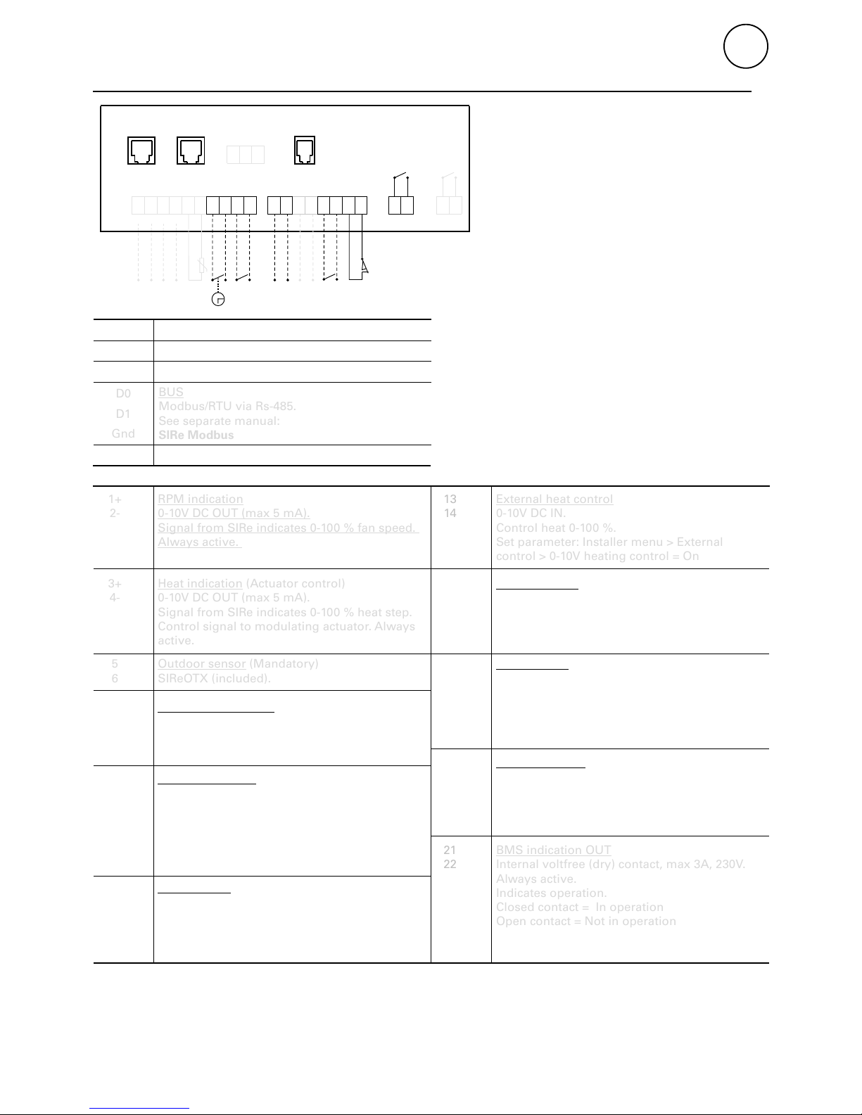
External rpm
0-10V DC IN.
Control fan speed 0-100 %.
Set parameter: Installer menu > External control
> 0-10V Fan control = On
RJ12 (6/6) SIRe internal communication
RJ12 (6/6) SIRe internal communication
BUS
Modbus/RTU via Rs-485.
See separate manual:
SIRe Modbus
RJ11 (4/4) Pin 1+2 and 3+4, SIReRTX (accessory)
RPM indication
0-10V DC OUT (max 5 mA).
Signal from SIRe indicates 0-100 % fan speed.
Always active.
Heat indication (Actuator control)
0-10V DC OUT (max 5 mA).
Signal from SIRe indicates 0-100 % heat step.
Control signal to modulating actuator. Always
active.
Outdoor sensor (Mandatory)
SIReOTX (included).
External alarm IN
External voltfree (dry) contact.
Closes to indicate an alarm. If used for filter
guard, set Parameter:
Installer menu > Filter guard > External filter
guard = On
Always active.
External heat control
0-10V DC IN.
Control heat 0-100 %.
Set parameter: Installer menu > External
control > 0-10V heating control = On
Setback temperature
External voltfree (dry) contact.
Close to activate night temperature.
Always active.
Door contact (Mandatory)
External voltfree (dry) contact. SIReDC
(included) or other contact (e.g. in BMS or door
automatic).
Door open = Closed contact
Door closed = Open contact
BMS indication OUT
Internal voltfree (dry) contact, max 3A, 230V.
Always active.
Indicates operation.
Closed contact = In operation
Open contact = Not in operation
BMS Alarm out
Internal voltfree (dry) contact, max 3A, 230V.
Always active. Indicates alarm.
Closed contact = Alarm
Open contact = No alarm
External on/off
External voltfree (dry) contact. Closes to
activate system.
Set parameter: Installer menu > External
control > External On/Off = On
Functions
Terminal
5
6
7
8
9
10
11
12
Connecting external control - including BMS functions
7 89101112
15 161718
19 20
COM 1 COM 2
BUS
ROOM
SIReC1X
SIReA1X
123
D0
D1
Gnd
4
5
6
13 14
+
-
21 22
+
-
+-
+-
1+
2-
3+
4-
13
14
15
16
17
18
19
20
21
22
COM1
COM2
D0
D1
Gnd
ROOM
Page 25

Main offi ce
For latest updated information and information
about your local contact: www.frico.se
Art no: 201855, 20171113, SÄ
 Loading...