

Frico SIReFAEMX, SIReFAX Original Instructions Manual
SIRe Advanced Fan Heater
Electric
With quick guide
SIReFAX
SIReFAEMX
For wiring diagram, please see last pages
Original instructions
.... 102
IT
.... 82
ES
.... 122
NL
.... 142
NO
.... 182
RU
.... 162
PL
.... 22
GB
.... 2
SE
.... 42
DE
.... 62
FR
SIRe Advanced Fan Heater Electric
22
GB
0
1
2
3
45
6
7
8
9
0
1
2
3
45
6
7
8
9
To run the unit
temporarily
without external
control select
mode 0.
Each unit should
have a unique ID on
its SIReB1X card.
Quick guide/start up
Check that all constituent parts are present
(see section Constituent parts).
Advice about location
PC board Base SIReB1X and PC board HUB
SIReA1X are installed close to the unit.
Control unit SIReUA1 has an integrated room
temperature sensor and is installed so that
it is easily accessible to the user. Wiring
between the PC Board Base SIReB1X and
heating fan must be laid for 230V.
RJ12 (6p/6c) modular cables, which are
available in different lengths, are used to connect the PC board and the control unit. Longer cables are available as options. Maximum
cable lengths see section Options.
To prevent unauthorised people from accessing the Control unit it can instead be placed
in another area and an external room sensor,
SIReRTX (option), can be installed in the
premises to sense the correct temperature.
Note! Internal sensor SIReIT02 shall be
mounted in the fan exhaust in the fan heater
unit in intended holder.
Connect the system
In control board base SIReB1X the unit is
connected further with RJ12 (6p/6c) modular
cable if several units are to be connected in
parallel.
If an external room temperature sensor SIReRTX (option) is used it is connected using
modular cable RJ11 (4p/4c) on HUB SIReA1X.
Outdoor sensor SIReOTX is connected to
the terminal block on PC board Hub SIReA1X
Control board Base SIReB1X in/at the unit
and control unit SIReUA1 are connected by
PC board HUB SIReA1X with RJ12 (6p/6c)
modular cables, after the other units are powered up.
Power supply for electric heat must be connected separately (check manual for the fan
heater unit).
Wiring diagrams
The wiring diagrams are in a separate section
at the end of this manual.
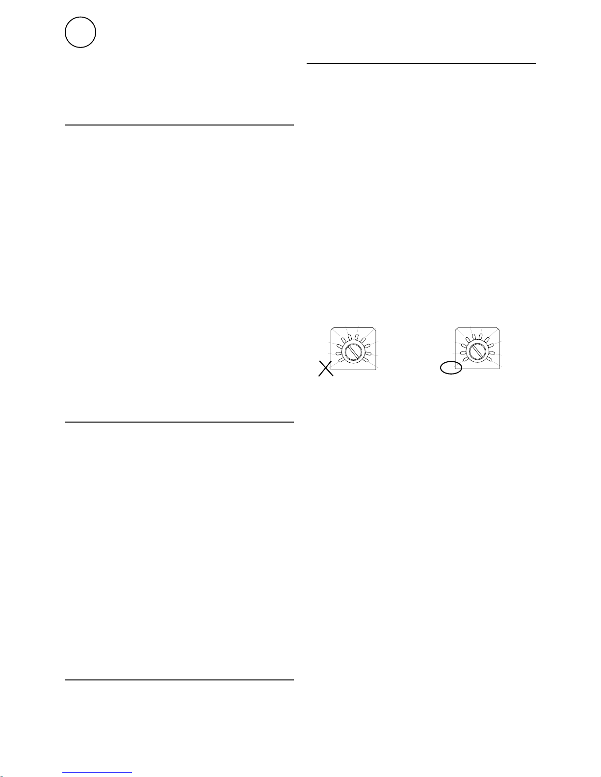
Enter ID/Operation without control unit
The control system can control one or more
units in parallel (max 9). Each unit must get
a unique ID number (1-9) which is set in the
ID selector of the PC board. E.g. Unit 1: ID=1,
unit 2: ID=3
If the external control for some reason has
not been installed the unit can still be run
temporarily. The ID selector is then set to
mode 0 see the image below.
The function is half speed and half heating
output
When the ID number must be changed the
unit must be disconnected from power.
SIRe Advanced Fan Heater Electric
23
GB
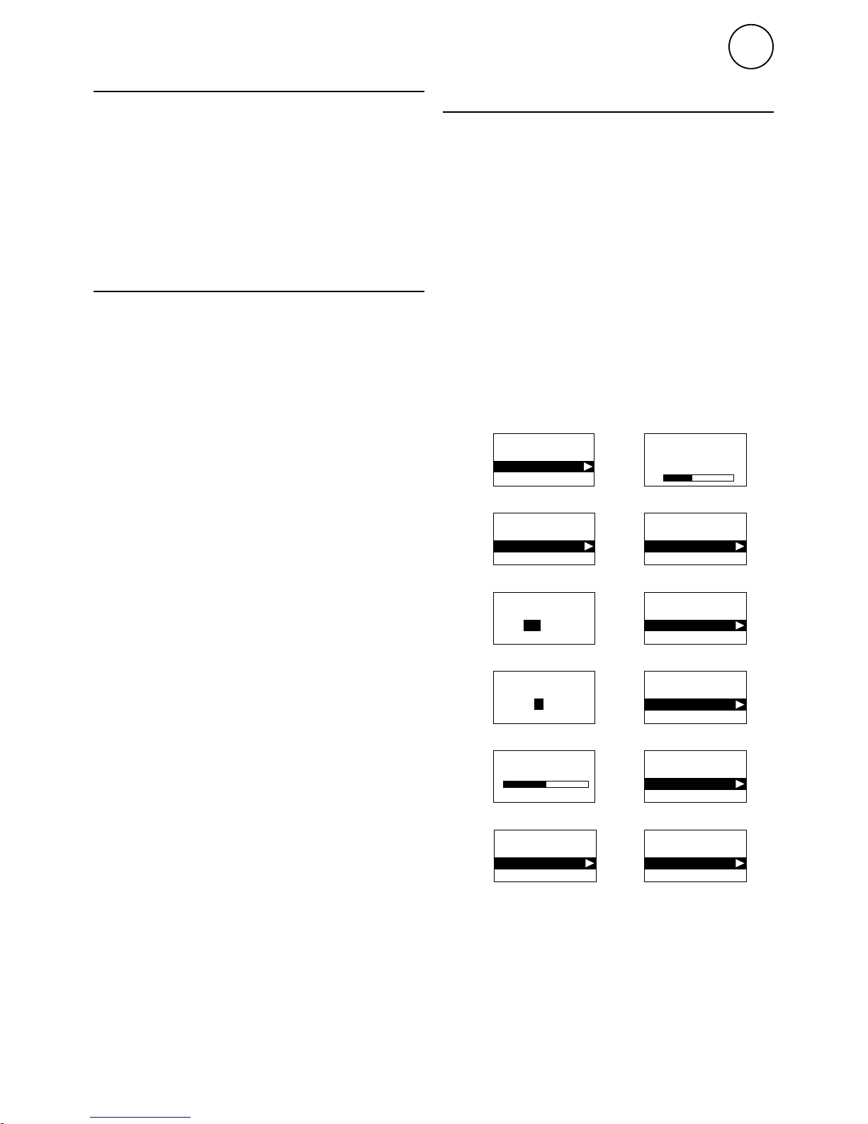
Start-up wizard
Start-up wizard
Fan step 1-5
Heating step off-3
Set language
English
Start-up wizard
1
Start-up wizard
Set temp. unit
°C
°F
2
Start-up wizard
Set date
20 11-05-28
YYYY-MM-DD
3
Start-up wizard
Set time
14:07
24h format
4
Start-up wizard
Function test
Start test
Skip test
5
Start-up wizard
Function test
Test completed
Restart test
6
Start-up wizard
Start-up finished
Proceed
Restart wizard
10
Start-up wizard
External filter guard
OFF
ON
8
Start-up wizard
Mixing cabinet on/off
OFF
ON
9
Start-up wizard
Eco / Comfort
Comfort mode
Eco mode
7
Screen function test
Checking system...
Start up
System supplied with power. At the first start
up, the start-up wizard is run and the basic
settings are made. Fan and heating steps
are tested through the test program. Then a
status window is displayed.
At the first start up alarm and error codes
can occur, these will usually be reset without
actions.
Unit with mixing cabinet
Damper motor PSM01 must be installed on
the throttle spindle to the mixing cabinet.
Electrical connection between the damper
motor and PC board HUB SIReA1X and 230V
power supply (see the wiring diagram at the
end of the manual).
Start up
Select mixing cabinet On in the start-up
wizard.
SIRe Advanced Fan Heater Electric
24
GB
Quick guide/start up
Advice about location 22
Connect the system 22
Wiring diagrams 22
Enter ID/Operation without control unit 22
Start up 23
Unit with mixing cabinet 23
Start up 23
Constituent parts
SIReFAX (without mixing cabinet) 25
SIReFAEMX (with mixing cabinet) 26
Option 27
Operating modes
Operating modes (without mixing cabinet) 28
Operating modes (with mixing cabinet) 28
Control unit SIReUA1
Overview 29
Statuswindow 29
Main menu
Current settings 30
Temperature settings 30
Fan control 30
System on/off 30
Installer menu 30
Installer menu
Installer status screen 31
Week program 31
Fan settings 32
Heating settings 32
External filter guard 34
Mixing cabinet 34
Filter guard settings 34
External control (BMS) 35
General settings 37
Service menu 37
Alarm and error codes
Displaying alarm and error codes 38
Reset alarm 38
Power failure 38
Overheat protection 38
Wiring diagrams, see last pages
Contents
SIRe Advanced Fan Heater Electric
25
GB
Type Description HxWxD
[mm]
L
[m]
SIReUA1 Control unit Competent and Advanced 120x70x35
SIReB1X External PC Board Base 202x139x50
SIReIT02 Internal temperature sensor 1
SIReA1X PC Board HUB Advanced 202x139x50
SIReOTX Outdoor temperature sensor 70x33x23
SIReCC603 Modular cable RJ12 (6/6) 3
SIReCC605 Modular cable RJ12 (6/6) 5
SIReCC,
modular cable
SIReOTX,
outdoor temperature
sensor
SIReA1X,
PC board HUB
Advanced
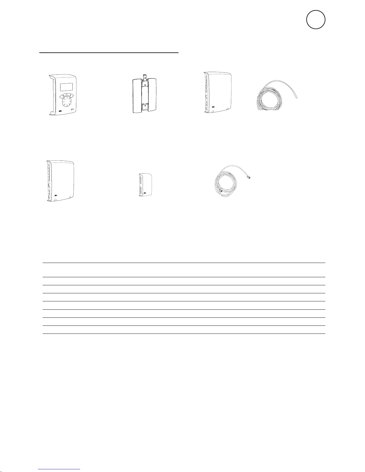
Dimensions constituent parts
SIReUA1,
control unit
Competent and
Advanced
Wall unit cover SIReIT02, internal
temperature sensor
2 m
SIReB1X, External
PC board Basic
SIReFAX (without mixing cabinet)
Constituent parts

SIRe Advanced Fan Heater Electric
26
GB
90
0
30
60
30
60
0
90
Type Description HxWxD
[mm]
L
[m]
SIReUA1 Control unit Competent and Advanced 120x70x35
SIReB1X External PC Board Base 202x139x50
SIReIT02 Internal temperature sensor 1
SIReA1X PC Board HUB Advanced 202x139x50
SIReOTX Outdoor temperature sensor 70x33x23
PSM01 Damper motor 230V 241x116x88
SIReCC603 Modular cable RJ12 (6/6) 3
SIReCC605 Modular cable RJ12 (6/6) 5
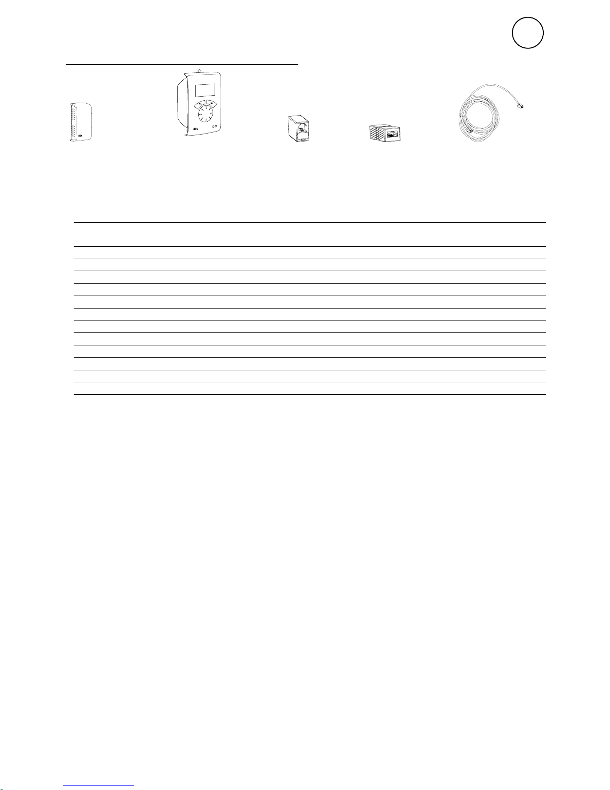
SIReCC,
modular cable
SIReA1X,
PC board HUB
Advanced
Dimensions constituent parts
SIReOTX,
outdoor
temperature sensor
SIReUA1,
control unit
Competent and
Advanced
Wall unit cover SIReIT02, internal
temperature sensor 2 m
PSM01, damper
motor
SIReB1X, External
PC board Basic
SIReFAEMX (with mixing cabinet)
SIRe Advanced Fan Heater Electric
27
GB
*) See separate manual.
Type RSK-no. E-no. Description HxWxD L
[m]
SIReRTX 673 09 22 87 510 12 External room temperature sensor 70x33x23 10
SIReUR* 673 09 21 87 510 11 Kit for recessed installation 114x70x50
SIReCJ4 Joint piece for two pcs. RJ11 (4/4)
SIReCJ6 Joint piece for two pcs. RJ12 (6/6)
SIReCC603 673 09 23 87 510 13 Modular cable RJ12 (6/6) 3
SIReCC605 673 09 24 87 510 14 Modular cable RJ12 (6/6) 5
SIReCC610 673 09 25 87 510 15 Modular cable RJ12 (6/6) 10
SIReCC615 673 09 26 87 510 16 Modular cable RJ12 (6/6) 15
SIReCC403 673 09 27 87 510 17 Modular cable RJ11 (4/4) 3
SIReCC405 673 09 28 87 510 18 Modular cable RJ11 (4/4) 5
SIReCC410 673 09 29 87 510 19 Modular cable RJ11 (4/4) 10
SIReCC415 673 09 30 87 510 20 Modular cable RJ11 (4/4) 15
SIReCJ6, joint
piece
SIReCJ4, joint
piece
SIReRTX, external
room temperature
sensor
SIReCC,
modular cable
Max. cable lengths
Modular cable RJ12 (6p/6c) between SIReUA1 and SIReA1X: max. 50 m.
Modular cable RJ12 (6p/6c) between SIReA1X and SIReB1(X): max. 10 m.
Modular cable RJ12 (6p/6c) between two SIReB1(X): max. 50 m.
Modular cable RJ11 (4p/4c) to room sensor SIReRTX: max. 20 m.
Cable for outdoor sensor SIReOTX (not modular): max. 50 m.
Total cable length permitted in the system is a maximum of 300 m.
Option
SIReUR, kit
for recessed
installation
SIRe Advanced Fan Heater Electric
28
GB
Operating modes
Operating modes (without mixing cabinet)
Control is based on the three operating
modes:
•Thermostat/Manualfan
•Thermostat/Automaticfan
•Manual
Thermostat / Manual fan
The thermostat just controls the heating and
the fan runs continually. The fan speed is set
manually. The fan symbol is marked in the
status window, select desired speed with the
rotary dial and confirm. (High speed limit is
step 4 for SE06-15 and step 2 for SE20/30).
When the setpoint value is fallen below by
0.5 K the first heating step is engaged , if the
temperature falls further the next heating step
is engaged, etc. (SE06-15, 20 has 2 heating
steps, SE30 has 3 heating steps).
The difference between the set point value
and the room temperature that controls the
engagement of the Heating step is set under
Heating step diff., see Installer menu > Settings heating > Heating step diff.
Thermostat / Automatic fan
The thermostat controls both the heating and
the fan. The fan speed is set manually in the
status window.
Manual
The fan speed and heating is set manually in
the status window. The heating can be set to 2
or 3 steps. Heating is blocked by the outdoor
temperature, see: [Installer menu > Settings
heating > Outdoor temp. limit]
Operating modes (with mixing cabinet)
The control is based on two operating modes:
Thermostat / Manual fan
Manual
Thermostat / Manual fan
The thermostat just controls the heating and
the fan runs continually. The fan speed is set
manually. The fan symbol is marked in the
status window, select desired speed with the
rotary dial and confirm.
Day mode
In day mode or if no week program is
activated, the fan runs continuously at the
fixed fan control and the damper is open
according to the setting under Day damper
pos.. The heating is controlled in steps via the
room temperature. If the inflow temperature
drops below the set minimum value, heat
connects even if it is sufficiently warm in the
premises.
Night mode
Night time (when the week program is
activated or via external signal for night
reduction) the damper is fully closed or open
according to the setting under Night damper
pos.. The fan is controlled by the room
temperature and the heating is controlled in
steps. When the desired temperature in the
premises has been reached, the fan switches
off and the damper is closed.
Manual
The fan speed and heating is set manually in
the status window. The heating can be set to 2
or 3 steps. Heating is blocked by the outdoor
temperature, see: [Installer menu > Settings
heating > Outdoor temp. limit]
SIRe Advanced Fan Heater Electric
29
GB
-5
.0
OUT °C
19
.0
IN °C
OFF
Fan speed step
Forward arrow
Heating step
Week program
Day
Week program
Night
Week program
Out of operation
Rotary dial
Run signal Green led
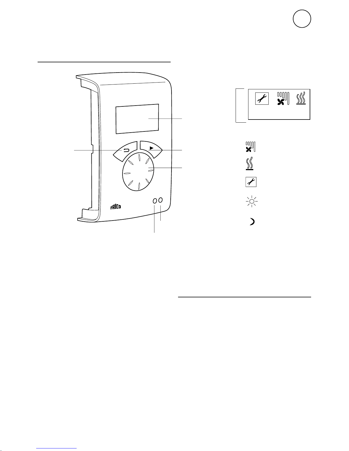
Explanations
Statuswindow
The display shows prevailing room
temperature, outdoor temperature, fan and
heating step and day, night mode, or Off when
week program is used.
This also displays whether the control is set
to auto mode or manual mode.
Forward arrow
Confirm selection and proceed.
Rotary dial
Scroll between alternatives
Back arrow
Go back.
After three minutes the control unit goes back
to displaying the status window.
Statuswindow
For thermostat/manual control of the fan and
heating the relevant symbol is marked in the
status window with the forward arrow. Steps
can then be set, confirm with the forward
arrow. For description, see section Operating
modes.
Press the forward arrow to access the main
menu.
Statuswindow
Back arrow
Control unit SIReUA1
Overview
Meny
Alarm Red led
 Loading...