

Frico sirefa, sirefawm Original Instructions Manual
Original instructions
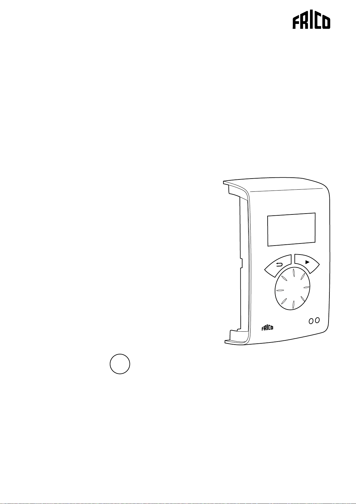
SIRe Advanced
Fan Heater - Water
With quick guide
SIReFA
SIReFAWM
.... 22
SE
ES
PL
.... 2
.... 82
.... 162
GB
IT
RU
.... 102
.... 182
For wiring diagram, please see last pages.
DE
NL
.... 42
.... 122
FR
NO
.... 62
.... 142
GB
45
45
SIRe Advanced Fan Heater Water
Quick guide/start up
Check that all constituent parts are present
(see section Constituent parts).
Advice about location
PC board HUB SIReA1X is installed close to
the unit.
Control unit SIReUA1 has an integrated
room temperature sensor and is installed so
that it is easily accessible to the user. RJ12
(6p/6c) modular cables, which are available in
different lengths, are used to connect the PC
board and the control unit. Longer cables are
available as options. Maximum cable lengths
see section Options.
To prevent unauthorised people from
accessing the Control unit it can instead
be placed in another area and an external
room sensor, SIReRTX (option), can be
installed in the premises to sense the correct
temperature.
Connect the system
Wiring diagrams
The wiring diagrams are in a separate section
at the end of this manual.
When external PC board Base SIReB1X is
used, wiring between the PC board base and
the unit must be done. Please see separate
manual for SIReB1X.
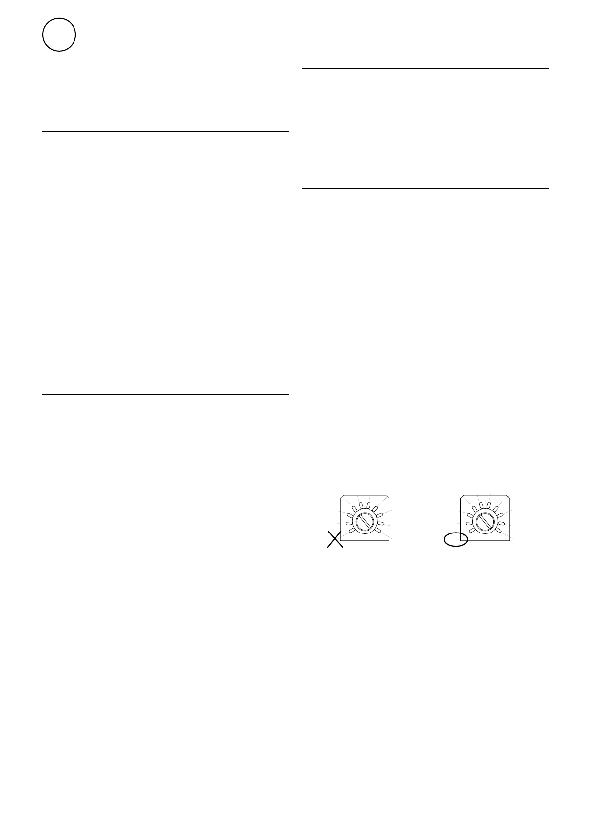
Enter ID/Operation without control unit
The control system can control one or more
units in parallel (max 9). Each unit must get
a unique ID number (1-9) which is set in the
ID selector of the PC board. E.g. Unit 1: ID=1,
unit 2: ID=3
If the external control for some reason has
not been installed the unit can still be run
temporarily. The ID selector is then set to
mode 0 see the image below.
The function is half speed and heating is on.
When the ID number must be changed the
unit must be disconnected from power.
In control board base SIReB1(X) the unit is
connected further with RJ12 (6p/6c) modular
cable if several units are to be connected in
parallell.
If an external room temperature sensor
SIReRTX (option) is used it is connected
using modular cable RJ11 (4p/4c) on HUB
SIReA1X.
The actuator for water control and outdoor
sensor SIReOTX is connected on PC Board
HUB SIReA1X.
Transformer for voltage supply of the valve
actuator is connected with quick terminal
block on PC Board Base SIReB1(X) (230V)
and 24V and onward to the actuator.
If return water temp. sensor SIReWTA is
used, it is connected with modular cable RJ11
(4p/4c) on PC Board Base SIReB1(X).
Control board Base SIReB1(X) in/at the
unit and control unit SIReUA1 are connected
by PC board HUB SIReA1X with RJ12 (6p/6c)
modular cables, after the other units are
powered up.
For fixed installation requirements, remove
the supplied cable and plug. Perform the
installation in accordance with applicable
regulations.
22
3
2
1
0
Each unit should have
a unique ID on its
SIReB1X card.
6
7
8
9
3
2
1
0
To run the unit
temporarily
without external
control select
mode 0.
6
7
8
9
SIRe Advanced Fan Heater Water
1
2
3
4
5
6
GB
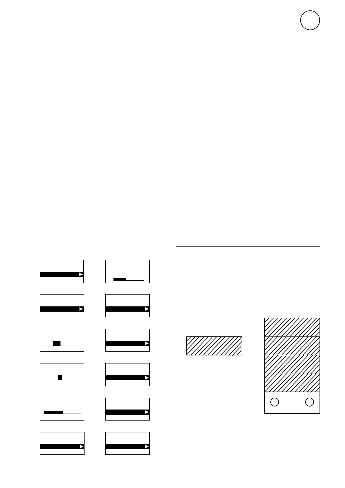
Start up
System supplied with power. At the first start
up, the start-up wizard is run and the basic
settings are made. Fan and heating steps
are tested through the test program. Then a
status window is displayed.
At the first start up alarm and error codes
can occur, these will usually be reset without
actions.
Unit with mixing cabinet
When a mixing cabinet is used the supplied
Return temp. sensor SIReWTA must be
installed. SIReWTA is a clamp-on sensor
which is installed on the return water pipe as
close to the coil as possible. The sensor must
be insulated so it is not influenced by the
ambient temperature.
In order for the Return temp. Sensor to
detect the correct temperature in the return
circuit when the valve actuator is closed, a
circulation pump must be installed in the
secondary circuit.
Damper motor PSM01 must be installed on
the throttle spindle to the mixing cabinet.
Electrical connection between the damper
motor and PC board HUB SIReA1X and
transformer ST23024 (see the wiring diagram
at the end of the manual).
Start up
Start-up wizard
Start-up wizard
1
Set language
English
Start-up wizard
2
Set temp. unit
°C
°F
Start-up wizard
3
Set date
20 11-05-28
YYYY-MM-DD
Start-up wizard
4
Set time
14:07
24h format
Screen function test
Start-up wizard
Fan step 1-5
Heating step off-1
Start-up wizard
6
Function test
Test completed
Restart test
Start-up wizard
7
Eco / Comfort
Comfort mode
Eco mode
Start-up wizard
8
External filter guard
OFF
ON
Select mixing cabinet On in the start-up
wizard.
Jumper settings
Actuator SDM24 (included in the valve kit) is
adjustable, this is done with jumpers. These
are located under the hatch of the actuator.
To SDM24 to work with SIRe the setting
should be as follows:
1-4, 6:Jumper in place
5:Jumper not in place
Checking system...
Start-up wizard
5
Function test
Start test
Skip test
Mixing cabinet on/off
Start-up wizard
10
Start-up finished
OFF
ON
Jumper 4 and 6 are not in use.
Proceed
Restart wizard
Start-up wizard
9
23

GB
SIRe Advanced Fan Heater Water
Contents
Quick guide/start up
Advice about location 22
Connect the system 22
Wiring diagrams 22
Enter ID/Operation without control unit 22
Start up 23
Unit with mixing cabinet 23
Start up 23
Jumper settings 23
Constituent parts
SIReFA (without mixing cabinet) 25
SIREFAWM (with mixing cabinet) 26
Operating modes
Operating modes (without mixing cabinet) 29
Operating modes (with mixing cabinet) 29
Control unit SIReUA1
Overview 30
Statuswindow 30
Main menu
Current settings 31
Temperature settings 31
Fan control 31
System on/off 31
Installer menu 31
Installer menu
Installer status screen 32
Week program 32
Fan settings 33
Heating settings 33
Filter guard settings 35
External filter guard 35
Mixing cabinet 35
External control (BMS) 36
General settings 37
Service menu 37
Alarm and error codes
Displaying alarm and error codes 38
Reset alarm 38
Overheat protection 38
Power failure 38
Frost protection function 38
Wiring diagrams, see last pages
24
SIRe Advanced Fan Heater Water
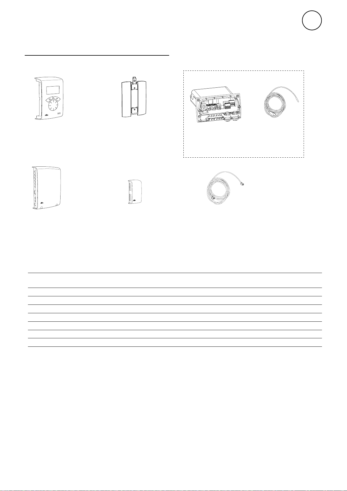
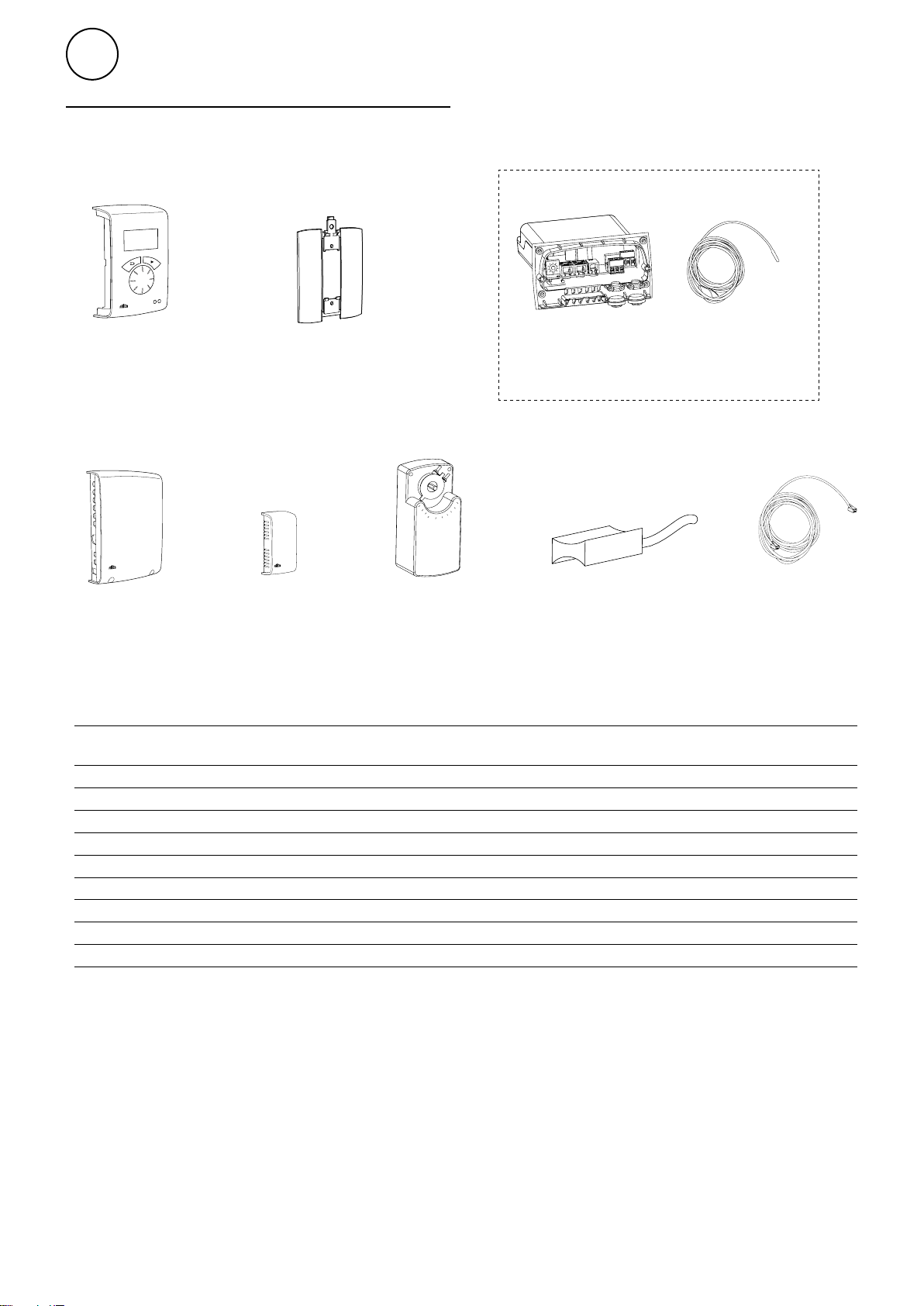
Constituent parts
SIReFA (without mixing cabinet)
Integrated in fan heater
PE N L
SUPPLY 230V
ACTUATOR
X3
X4
230V
X5
ROOM
C1
C2
GB
SIReUA1,
control unit
Competent and
Wall unit cover
SIReB1,
integrated PC
Board Base
SIReIT, internal
temperature
sensor
Advanced
SIReA1X,
PC board HUB Advanced
SIReOTX,
outdoor temperature
SIReCC,
modular cable
sensor
Dimensions constituent parts
Type Description HxWxD
[mm]
SIReUA1 Control unit Competent and Advanced 120x70x35
SIReB1 Integrated PC board Base
SIReIT Internal temperature sensor 1
SIReA1X PC Board HUB Advanced 202x139x50
SIReOTX Outdoor temperature sensor 70x33x23
SIReCC603 Modular cable RJ12 (6/6) 3
SIReCC605 Modular cable RJ12 (6/6) 5
L
[m]
25
GB
90
0
30
60
30
60
0
90
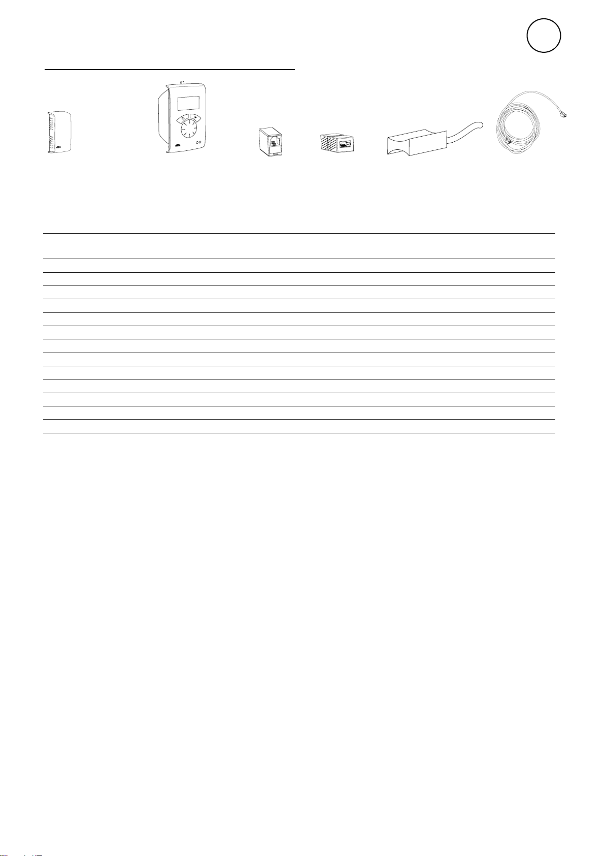
SIRe Advanced Fan Heater Water
SIREFAWM (with mixing cabinet)
PE N L
SUPPLY 230V
ACTUATOR
X3
X4
230V
X5
ROOM
C1
C2
SIReUA1,
control unit
Competent and
Wall unit cover
SIReB1, integrated
PC Board Base
SIReIT, internal
temperature
sensor
Advanced
SIReA1X,
PC board HUB
Advanced
SIReOTX,
outdoor
temperature
SMM24,
damper motor
SIReWTA,
clamp-on sensor
sensor
Dimensions constituent parts
Type Description HxWxD
[mm]
SIReUA1 Control unit Competent and Advanced 120x70x35
SIReB1 Integrated PC board Base
SIReIT Internal temperature sensor 1
SIReA1X PC Board HUB Advanced 202x139x50
SIReOTX Outdoor temperature sensor 70x33x23
SMM24 Damper motor 24V 241x116x88
SIReWTA Clamp-on sensor RJ11 (4/4) 3
SIReCC603 Modular cable RJ12(6/6) 3
SIReCC605 Modular cable RJ12 (6/6) 5
SIReCC,
modular cable
L
[m]
26
Option
SIRe Advanced Fan Heater Water
GB
SIReRTX, external
room temperature
sensor
Type RSK-no. E-no. Description HxWxD L
SIReRTX 673 09 22 87 510 12 External room temperature sensor 70x33x23
SIReUR* 673 09 21 87 510 11 Kit for recessed installation 114x70x50
SIReCJ4 Joint piece for two pcs. RJ11 (4/4)
SIReCJ6 Joint piece for two pcs. RJ12 (6/6)
SIReWTA Clamp-on sensor RJ11 (4/4)
SIReCC603 673 09 23 87 510 13 Modular cable RJ12 (6/6) 3
SIReCC605 673 09 24 87 510 14 Modular cable RJ12 (6/6) 5
SIReCC610 673 09 25 87 510 15 Modular cable RJ12 (6/6) 10
SIReCC615 673 09 26 87 510 16 Modular cable RJ12 (6/6) 15
SIReCC403 673 09 27 87 510 17 Modular cable RJ11 (4/4) 3
SIReCC405 673 09 28 87 510 18 Modular cable RJ11 (4/4) 5
SIReCC410 673 09 29 87 510 19 Modular cable RJ11 (4/4) 10
SIReCC415 673 09 30 87 510 20 Modular cable RJ11 (4/4) 15
SIReUR, kit
for recessed
installation
SIReCJ4,
joint piece
SIReCJ6,
joint piece
SIReWTA,
clamp-on sensor
SIReCC,
modular cable
*) See separate manual.
[m]
Max. cable lengths
Modular cable RJ12 (6p/6c) between SIReUA1 and SIReA1X: max. 50 m.
Modular cable RJ12 (6p/6c) between SIReA1X and SIReB1(X): max. 10 m.
Modular cable RJ12 (6p/6c) between two SIReB1(X): max. 50 m.
Modular cable RJ11 (4p/4c) to room sensor SIReRTX: max. 20 m.
Cable for outdoor sensor SIReOTX (not modular): max. 50 m.
Total cable length permitted in the system is a maximum of 300 m.
27
GB
SDM24
SDM24
SDM24
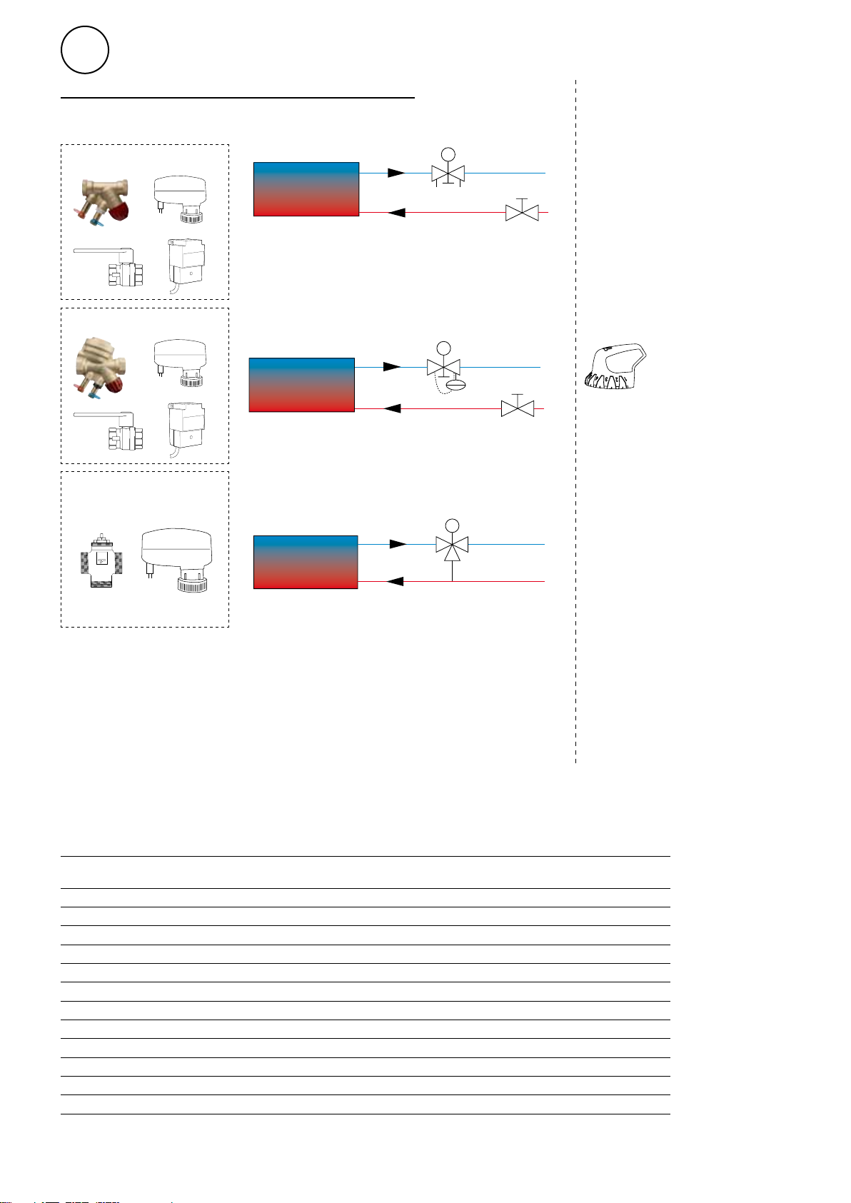
Water control - valve kit
SIRe Advanced Fan Heater Water
VMO
VMOP
VMT
TBVCM
AV
Water control - option
TBVCMP
AV
VAT, adjustment tool for
valve package.
TRVS
Type RSK-no. Description Connection
VMO15LF 673 09 47 Modulating DN15
VMO15NF 673 09 48 Modulating DN15
VMO20 673 09 49 Modulating DN20
VMO25 673 09 50 Modulating DN25
VMOP15LF 673 09 51 Pressure independent and modulating DN15
VMOP15NF 673 09 52 Pressure independent and modulating DN15
VMOP20 673 09 53 Pressure independent and modulating DN20
VMOP25 673 09 54 Pressure independent and modulating DN25
VMT15 Three way valve and modulating actuator DN15
VMT20 Three way valve and modulating actuator DN20
VMT25 Three way valve and modulating actuator DN25
VAT Adjustment tool for valve package
28
 Loading...