

Page 1
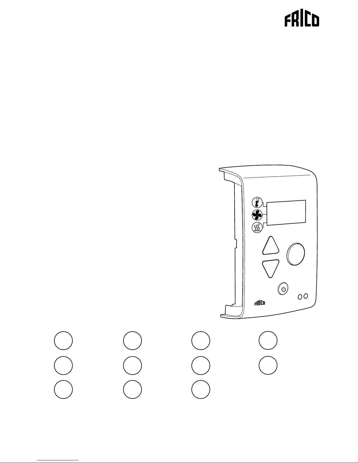
SIRe Basic
Quick guide
SIReB
C
Original instructions
.... 42
IT
.... 70
RU
.... 14
GB
.... 35
FR
.... 63
PL
.... 7
SE
....49
NL
.... 21
DE
.... 56
NO
....28
ES
.... 77
FI
Page 2
SIRe Basic
2
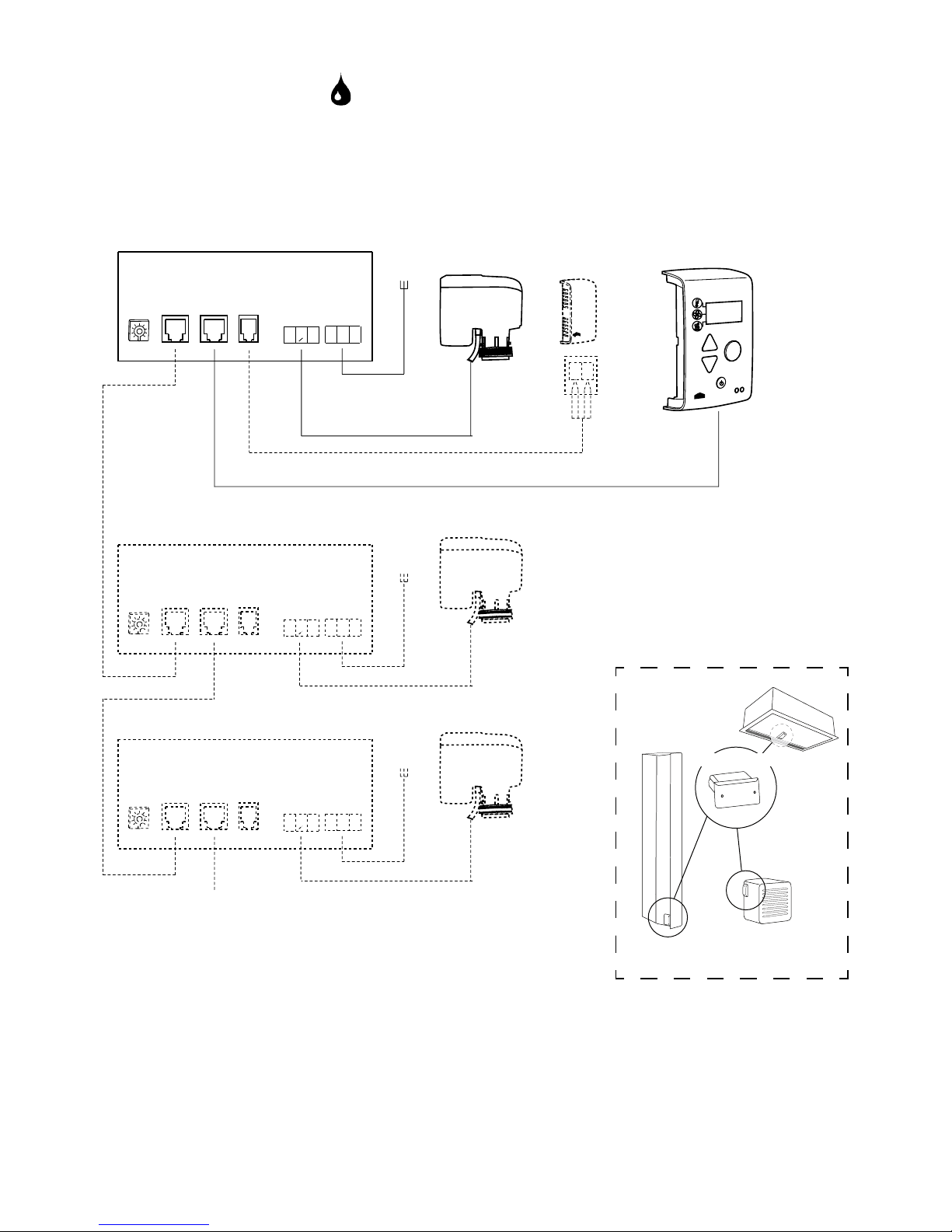
Wiring diagram - Basic
SIReB
SIReB1/B2/B1EC
C2X5C1
X4
ROOM
X3
Pot.
Unit ID
ACTUATOR
SUPPLY
N L
N
L
PE
L
~
230V~
C2X5C1
X4
ROOM
X3
Pot.
Unit ID
ACTUATOR
SUPPLY
N L
N
L
PE
L
~
230V~
C2X5C1
X4
ROOM
X3
Pot.
Unit ID
ACTUATOR
SUPPLY
N L
N
L
PE
L
~
230V~
SIReCC6XX (max 50 m)
SIReB1/B2/B1EC
SIReB1/B2/B1EC
SIReB1/B2/B1EC
SIReCC6XX
(max 50 m)
SIReCC6XX
(max 50 m)
SIReUB1
SIReRTX
(optional)
SD230
SD230
SD230
L=1,5m
L=2m
Page 3
3
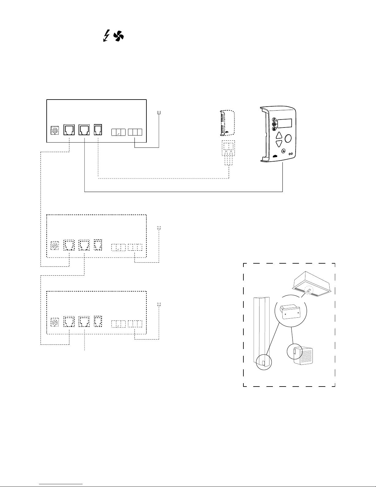
Wiring diagram
SIReB
SIReB1/B2/B1EC
C2X5C1
X4
ROOM
X3
Pot.
Unit ID
ACTUATOR
SUPPLY
N L
N
L
PE
L
~
230V~
C2X5C1
X4
ROOM
X3
Pot.
Unit ID
ACTUATOR
SUPPLY
N L
N
L
PE
L
~
230V~
C2X5C1
X4
ROOM
X3
Pot.
Unit ID
ACTUATOR
SUPPLY
N L
N
L
PE
L
~
230V~
SIReCC6XX (max 50 m)
SIReCC6XX
(max 50 m)
SIReCC6XX
(max 50 m)
SIReUB1
SIReRTX
(optional)
L=2m
SIReB1/B2/B1EC
SIReB1/B2/B1EC
SIReB1/B2/B1EC
Page 4
4
1
SE
GB
Wiring diagram - Advanced
SIRe B1/B2/B1EC
2
Page 5
5
!
=
=
OK
OK
4
3a
Wiring diagram - Advanced
8
7
0
1
2
3
4
5
6
9
!
3b
=
1
0
OK
Page 6
6
5
?
www.frico.se
Page 7
0
1
2
3
45
6
7
8
9
X5
C2
X4
C1
X3
ROOM
PE N L
SUPPLY 230V
ACTUATOR
230V
14
GB
SIRe Basic
Quick guide/Start up
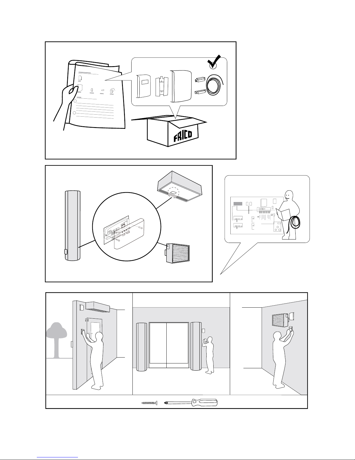
1. Check that all constituent parts are
present (see section Constituent parts).
2. Mount and connect all units and
components and where applicable
accessories (e.g. actuator), see wiring
diagram. When several units are connected
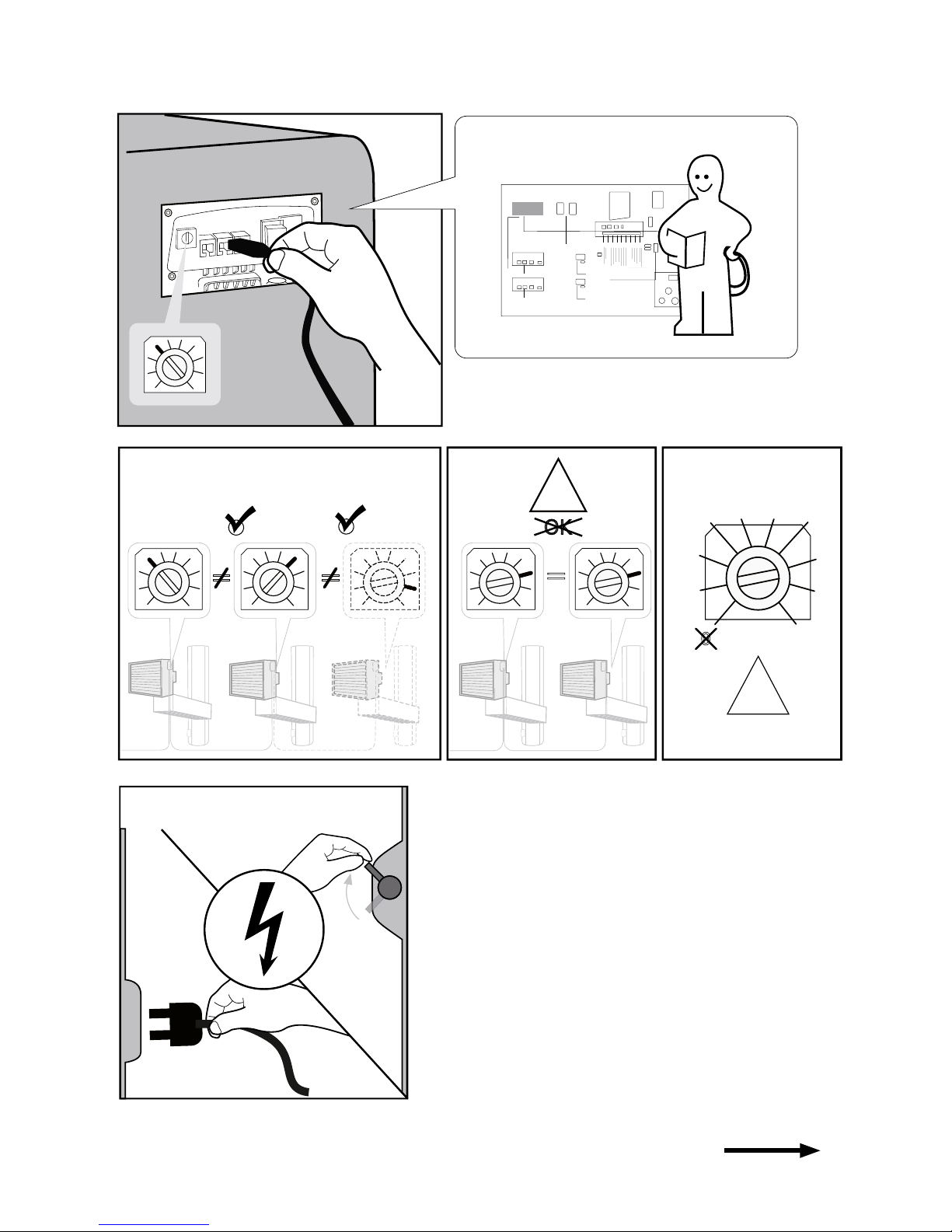
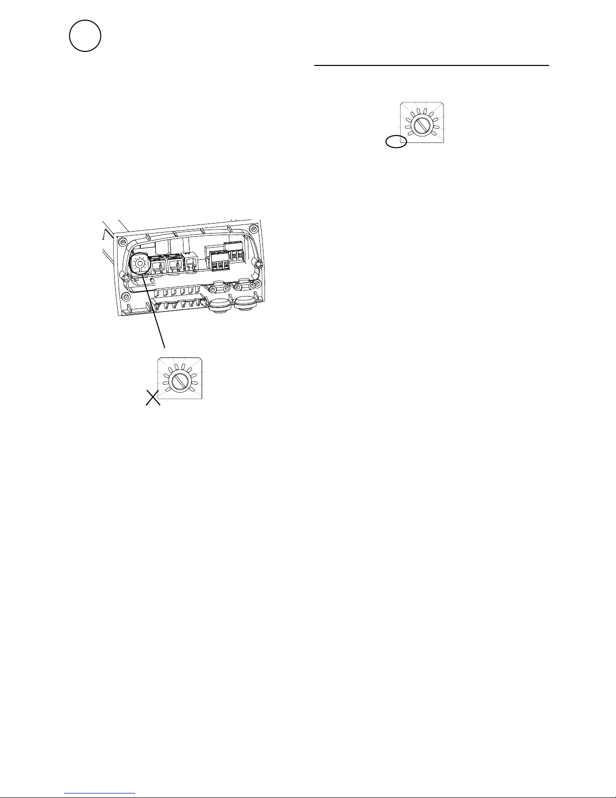
set a unique ID for each unit (1-9) which
is set in the ID selector of the SIReB1/B2/
B1EC.
Each unit should have
a unique ID on its
SIReB1/B2/B1EC card.
3. Power up all units.
4. If required, disconnect and reconnect
SIReUB1 to initialize the system control.
To run the unit
temporarily without
external control
select mode 0.
0
1
2
3
45
6
7
8
9
Operation without control unit
Page 8
20
-3
_1
C
208
.
+
+
+
+
+
+
30 - 60 s
15
GB
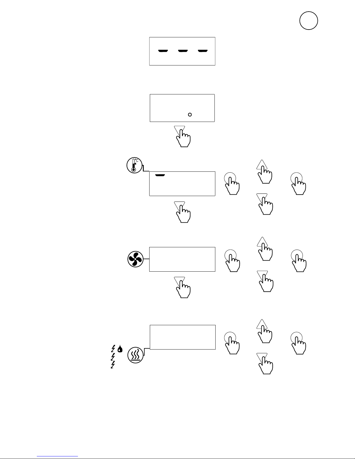
Activate heat
0 = No heat
1 = Heat step 1 possible
2 = Heat step 2 possible
(3 = Heat step 3 possible)
Heat steps controlled by thermostat.
Start up
Set desired room
temperature 5 - + 30 °C
Set fan steps
1 - 5
Prevailing room
temperature
Page 9
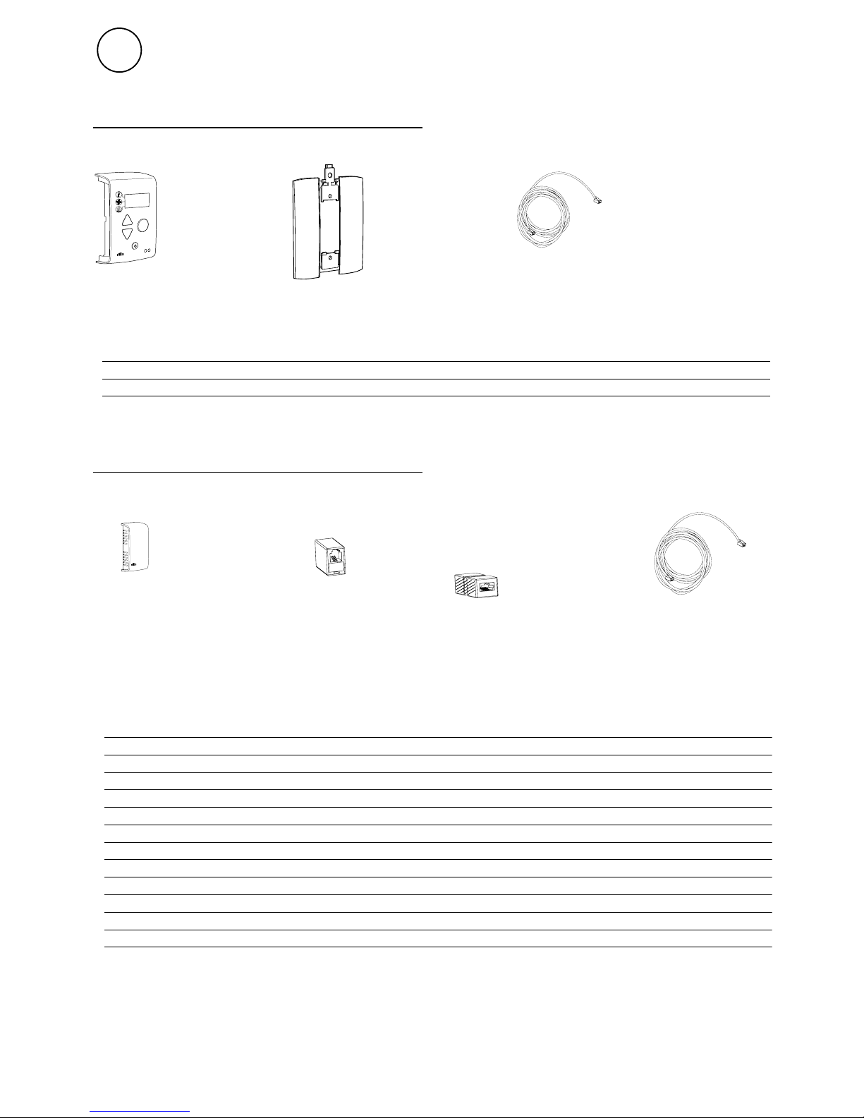
C
SIReUB1 SIReCC605
SIReRTX SIReCJ4 SIReCJ6
SIReCC
Type Description HxWxD L
[m]
SIReRTX External room temperature sensor 70x33x23 10
SIReCJ4 Joint piece for two pcs. RJ11 (4/4)
SIReCJ6 Joint piece for two pcs. RJ12 (6/6)
SIReCC603 Modular cable RJ12 (6/6) 3
SIReCC605 Modular cable RJ12 (6/6) 5
SIReCC610 Modular cable RJ12 (6/6) 10
SIReCC615 Modular cable RJ12 (6/6) 15
SIReCC640 Modular cable RJ12 (6/6) 40
SIReCC403 Modular cable RJ11 (4/4) 3
SIReCC405 Modular cable RJ11 (4/4) 5
SIReCC410 Modular cable RJ11 (4/4) 10
SIReCC415 Modular cable RJ11 (4/4) 15
16
GB
SIRe Basic
Constituent parts
Wall unit cover
SIReB
Option
Type Description HxWxD L
[m]
SIReUB1 Control unit with room temperature sensor 120x70x35
SIReCC605 Modular cable RJ12 (6/6) 5
Page 10
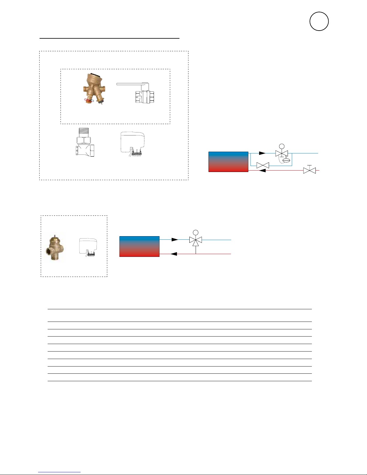
SD230
TRVS
VOT
TRVS
SD230
17
GB
Water control - valve system*
*) See separate manuals.
Water control - valve kit
SD230
TAC
AV
BPV10
SD230BPV10
AVTAC
VKF
VLSP
Type Description Connection
VLSP15LF
Pressure independent DN15
VLSP15NF
Pressure independent DN15
VLSP20
Pressure independent DN20
VLSP25
Pressure independent DN25
VLSP32
Pressure independent DN32
VOT15
Three way valve and actuator on/off DN15
VOT20
Three way valve and actuator on/off DN20
VOT25
Three way valve and actuator on/off DN25
Page 11
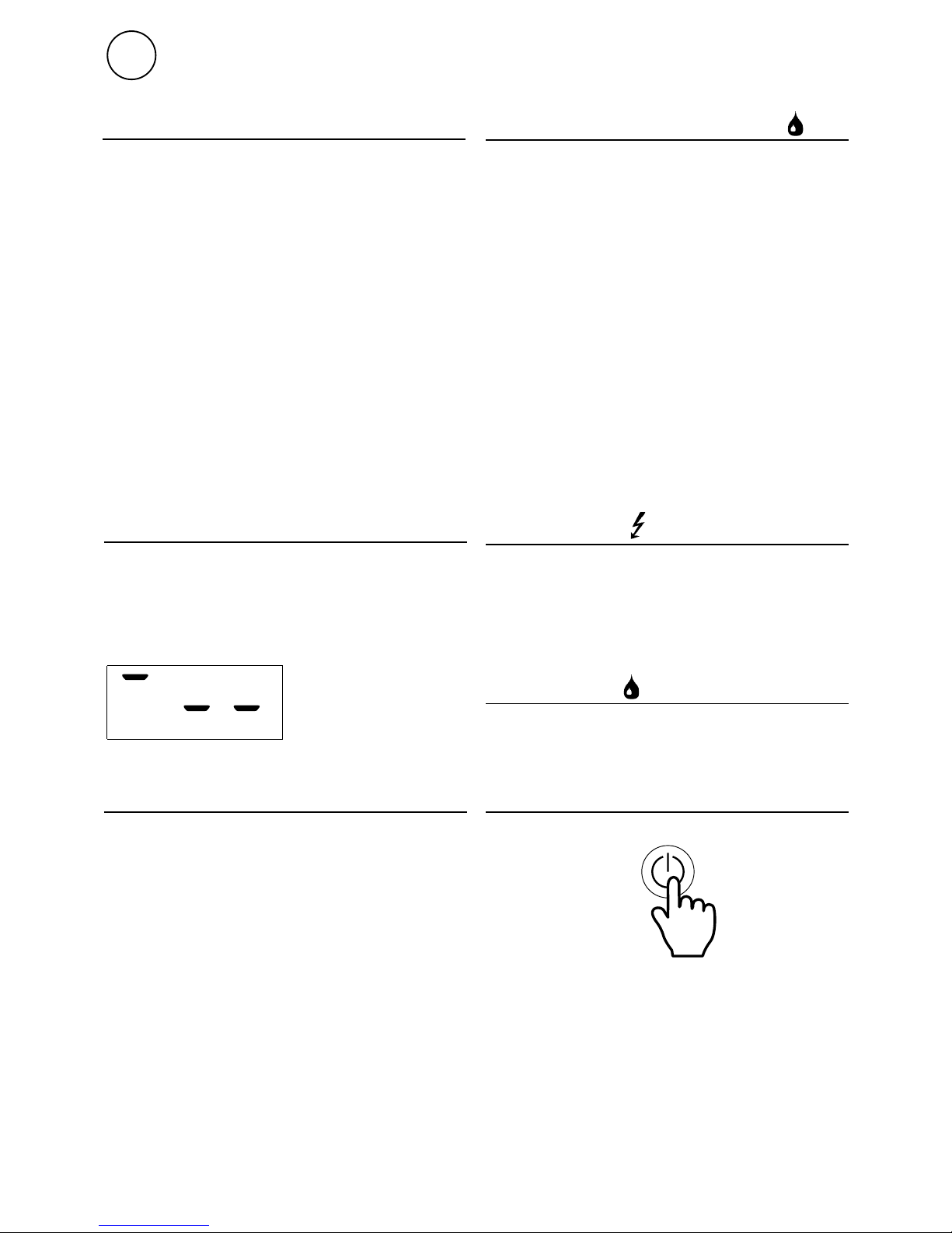
Heat regulation
When the room temperature drops below
the set point temperature the first heating
step is activated. If temperature continues to
drop, another heating step is activated (see
description below parameters P.00).
Operating modes fan heaters water
Set the maximum fan speed, heating step and
desired room temperature. The thermostat
is controlling the room temperature by
increasing/decreasing the fan speed. When
the desired room temperature is reached the
actuator/valve will close and the fan stops.
Maximum fan speed is limited to step 4.
If Parameter P04 is changed from 1 to 0 (see
list of parameters on next page) the fan runs
continuously on set speed and the thermostat
controls the heating on/off.
General
18
GB
SIRe Basic
Manual mode
Decrease the temperature setting below 5 °C
and the following symbols are shown in the
status window = manual mode.
In manual mode both fan- and heating steps
are controlled manually.
Fan over run
When heat has been activated the fan will
continue to run to cool down the unit. The
over run time is 180 seconds or shorter if the
internal temperature has dropped below
+30 °C.
Operating modes
Press the ON /OFF button for 2 seconds
to switch off the system. The unit’s safety
functions are still active when the system is
switched off, which means that the fan can
continue to run for a while.
System on/off
Operating modes Air curtains
Factory settings gives manual control of fan
and heating is controlled by thermostat on/off.
Set parameter P04 to 1 (see parameter menu
on the next page) to get the thermostat to
control both fan and heating on/off.
Heat regulation
When the room temperature drops below the
setpoint, the valve is opening for heat.
Page 12
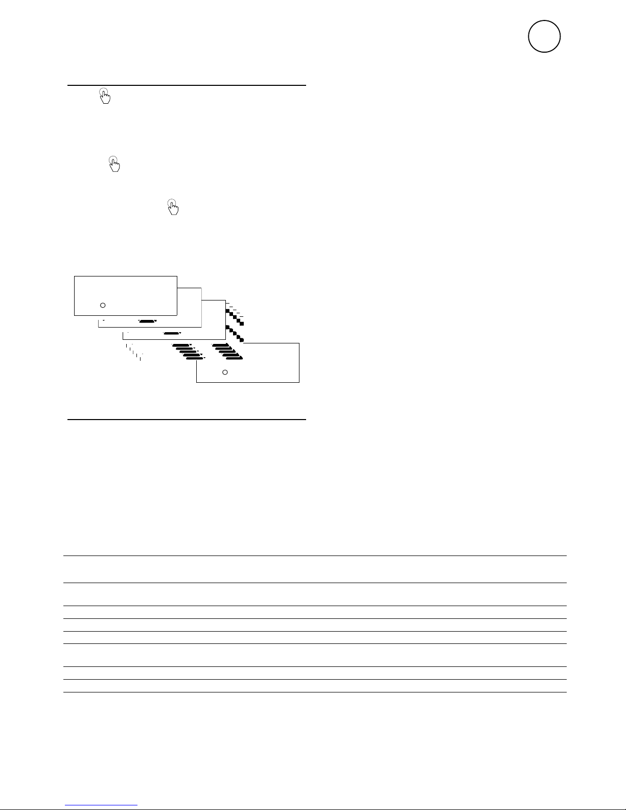
P13
.
P02
.
P02
.
P02
.
P02
.
P02
.
P02
.
P01
.
P00
.
Parameter description
P.00 Temperature difference heating steps
Sets the difference between heating steps in
auto mode for electric units, alternatively the
difference between fan speed steps for water
supplied fan heaters.
Parameter menu
Keep pressed until P00 is shown in the
status window. Use arrow up/down to scroll
between the parameters.
Use arrow up / down to scroll between the
parameters.
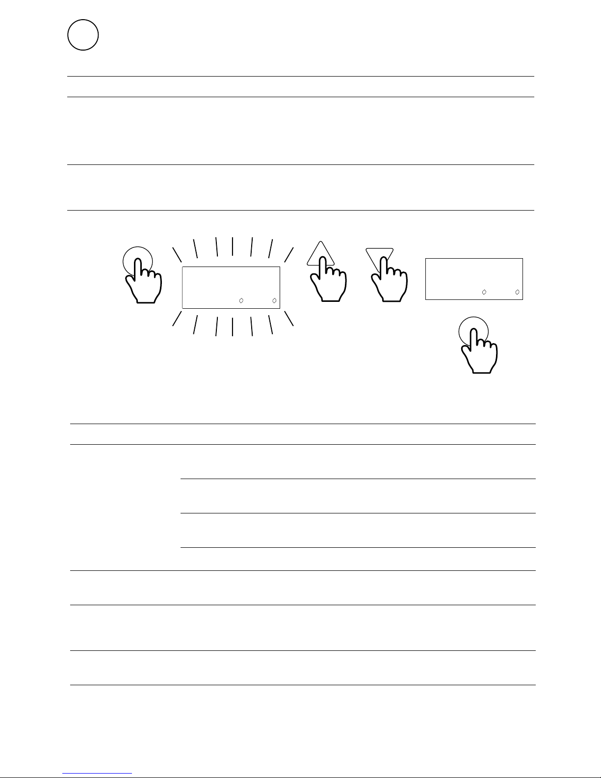
Press once to change a setting in the
parameter menu. Flashing values can be
adjusted using the arrow up/down and then
confirm. Keep the pressed to return to
the status window. (Returning automatically
to the status window after about 50 seconds).
19
GB
Installer menu
P.01 Overheating alarm ON/OFF
Possibility to block the alarm (only valdid for
units with internal temperature sensor). Note!
If the alarm function is blocked, it must be
ensured this does not affect the unit's safety.
P.02 Over run time
Time when the fan continue to run when the
heat has been on.
P.03 Temperature limit for over run
Over run time is cancelled if the internal
temperature drops below this set value (only
valid for units with internal temperature
sensor).
P.04 Fan control
Choose (0) or (1) operating mode, read more
under section Operating mode.
P.05 Internal temperature
Prevailing internal temperature. Only the
peak value is shown when several units are
connected (only valid for units with internal
temperature sensor).
P.06 - P.13 Run time
Run time for fan and heating steps.
List of parameters
Parameternumber
Description Setting
range
Factory
setting
P. 0 0
Temperature difference between heating steps alternatively
difference between fan speed steps.
0,5-10 1.0 °C (0,5 °C SWH)
P. 01 Overheting alarm ON/OFF ON=1; OFF=0 1/0 1
P.02 Over run time when heat has been activated 10-300 180 seconds
P.03 Temperature limit for fan over run 10-40 30 °C
P.04 Fan control 0/1
0 = air curtains
1 = fan heater
P.05 Display of unit internal/outlet temperature 0-100
P.06 - 13 Run time 0-99999
Page 13
res
.
Aot
.
20
GB
SIRe Basic
Alarm code starts to
flash
3 seconds
Alarm Cause Action
A.FA
Motor alarm Thermal switch has deployed. One
or several motors have overheated.
(Only units with withdrawn thermal
switches.)
Check that nothing is obstructing the
unit’s air intake and exhaust. When the
overheated motor has cooled the thermal
switch shuts again and the alarm can be
reset. At repeated alarms, check the motors,
replace damaged motors.
A.ot
Over heating
alarm
The temperature in the unit has
exceeded the alarm limit for
overheating. (Only applies to units
with internal unit temperature.)
Check that nothing is obstructing the unit’s
air intake and exhaust, the function of the
actuator/valve, return water and internal
temperature sensors in the unit
Alarm Cause Action
E.co
Communication
SIReB1/B2/B1EC has no
contact with SIReUB1.
Check connection between the SIReB1/B2/B1EC
and SIReUB1. Replace any modular cables.
Repeated errors, contact Frico.
PC board SIReB1/B2/B1EC
ID=0
Interrupt the power supply and select different
ID numbers for all SIReB1/B2/B1EC in the
system.
Two or more SIReB1/B2/B1EC
have the same ID-number.
Interrupt the power supply and select different
ID numbers for all SIReB1/B2/B1EC in the
system.
One or more SIReB1/B2/B1EC
do not have programs.
Contact Frico for support.
E.cF
ID-error Two or more SIReB1/B2/B1EC
in the system have different
programs.
Contact Frico for support.
E.rt
Room sensor
error
Error in or missing external
room sensor SIReRTX
connected to
SIReB1/B2/B1EC.
Always disconnect the power supply when
connecting or disconnecting sensors. Check
connection of the sensor.
E.It
Internal sensor
error
Fault on or missing internal
sensor in the unit (applies to
units with internal sensor).
Check connection of the sensor. If there is no
sensor, contact Frico for support.
E.ru
Room sensor
error
Fault on internal room sensor
in the control unit SIReUB1.
Check connections between SIReUB1 and
SIReB1/B2/B1EC. Replace any modular cables.
Check if an external sensor SIReRTX is working.
If the error is not rectified the SIReUB1 must be
replaced.
Page 14

Page 15

Page 16

Page 17

Main offi ce
For latest updated information and information
about your local contact: www.frico.se
Art no: 201854, 20171113, SÄ
 Loading...