

Page 1
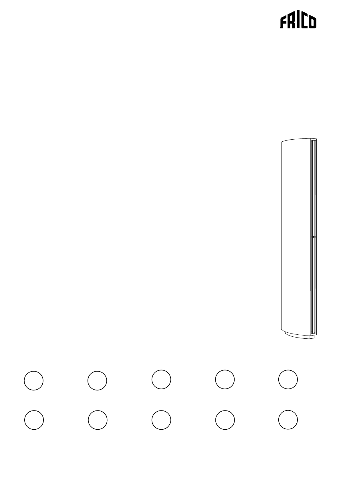
Original instructions
SFS
SE
IT
.... 12
.... 36
GB
NL
.... 17
.... 41
DE
NO
.... 21
.... 46
ES
RU
.... 26
.... 51
FR
PL
.... 31
.... 56
Page 2

SFS
SE
GB
NO
FR
DE
Introduktionssidorna består huvudsakligen av bilder. För översättning av de
engelska texter som används, se respektive språksidor.
The introduction pages consist mainly of pictures. For translation of the
English texts used, see the respective language pages.
Introduksjonssidene består hovedsakelig av bilder. For oversettelse av de
engelske tekstene, se de respektive språksidene
Les pages de présentation contiennent principalement des images. Consulter
la page correspondant à la langue souhaitée.
Die Einleitungsseiten bestehen hauptsächlich aus Bildern. Für die Übersetzung
der verwendeten Texte in englischer Sprache, siehe die entsprechenden
Sprachseiten.
ES
NL
IT
PL
RU
Las páginas introductorias contienen básicamente imágenes. Consulte la
traducción de los textos en inglés que las acompañan en las páginas del
idioma correspondiente.
De inleidende pagina's bevatten hoofdzakelijk afbeeldingen. Voor een vertaling
van de gebruikte Engelse teksten, zie de pagina's van de resp. taal.
Le pagine introduttive contengono prevalentemente immagini. Per le
traduzioni dei testi scritti in inglese, vedere le pagine nelle diverse lingue.
Początkowe strony zawierają głównie rysunki. Tłumaczenie wykorzystanych
tekstów angielskich znajduje się na odpowiednich stronach językowych.
Страницы в начале Инструкции состоят в основном из рисунков, схем и
таблиц. Перевод встречающегося там текста приведен в разделе RU.
2
Page 3
SFS
247
2200
M8
50
296
116
581
Fig. 1. Dimensions
3
Page 4
377
339
SFS
380
339
Ø48 (2x)
Seen from above - Connection above
Fig. 2 Connections W
118
168
118
168
Seen from above - Connection below
Seen from above - Connection above
Fig. 3 Connections E
min 120
Fig. 4 Minimum mounting distance
Seen from above - Connection below
4
Page 5
Accessories
SIRe
SIReB
SIReAC
SIReAA
SIReRTX 70x33x23 mm
SIReUR 114x70x50 mm
SIReWTA
SIReCJ4
SIReCJ6
SIReCC603 3 m
SIReCC605 5 m
SIReCC610 10 m
SIReCC615 15 m
SIReCC403 3 m
SIReCC405 5 m
SIReCC410 10 m
SIReCC415 15 m
SFS
C
SIReB
SIReAC/SIReAA
SIReUR
SIReWTA
SIReCJ4/SIReCJ6
VKF15LF
VKF15NF
VKF20
VKF25
VKF32
SD230
BPV10
SDM24
ST23024
VOT15 DN15
VOT20 DN20
VOT25 DN25
DN15
DN15
DN20
DN25
DN32
VLSP
VKF
SD230 BPV10
VOT
SIReRTX
SIReCC
VLP
VKF
SDM24 ST23024
FH1025 Flexible hose (DN25, 1" inside thread) for
easy connection to the pipe system.
SFSEH Extension hood, 100-1000 mm
SFSEH FH1025
5
Page 6
SFS E
SFS
SFS38/56E
SFS23/30E
°C°C°C
SIReB1
Transformer
145V
170V
230V
200V
Yellow
Orange
Red
Brown
Transformer
145V
170V
230V
200V
120V
Black
120V
100V
Green
100V
N
Blue
N
Blue
L
N
230V~
N
400V3~
Grey
Blue
Black
Black
SFS23E
°C°C°C
SFS30/38E
SFS56E
White
White
Motor
Internal
C2
protection
sensor
C1
ROOM
Actuator
230V~
Supply
230V~
6
Page 7

SFS W
SFS
SFS23W
Transformer
230V
200V
Yellow
Orange
Transformer
230V
200V
°C°C°C
°C°C°C
SIReB1
White
White
Motor
protection
sensor
Internal
170V
Red
170V
145V
Brown
145V
120V
120V
Black
100V
Green
100V
N
Blue
N
Blue
Black
SFS30/38W
SFS56W
Actuator
Supply
230V~
C2
C1
ROOM
230V~
230V~
7
Page 8

SIReB Basic
C2
X5
C1
X4
ROOM
X3
Pot.
Unit ID
ACTUATOR
SUPPLY
N L
N
L
PE
L
~
230V~
C2
X5
C1
X4
ROOM
X3
Pot.
Unit ID
ACTUATOR
SUPPLY
N L
N
L
PE
L
~
230V~
C2
X5
C1
X4
ROOM
X3
Pot.
Unit ID
ACTUATOR
SUPPLY
N L
N
L
PE
L
~
230V~
SIReCC6XX (max 50 m)
SIReCC6XX
(max 50 m)
SIReCC6XX
(max 50 m)
SIReUB1
SIReRTX
(optional)
L=2m
SIReB1/B2/B1EC
SIReB1/B2/B1EC
SIReB1/B2/B1EC
SFS E
SFS
Wiring diagrams for SIReAC Competent and SIReAA Advanced, see manuals for SIRe.
8
Page 9

SIReB Basic
SFS W
SFS
SIReB1/B2/B1EC
C2
Pot.
X5
Unit ID
SIReCC6XX
(max 50 m)
SIReB1/B2/B1EC
C2
Pot.
X5
Unit ID
C1
X4
C1
X4
ROOM
X3
ROOM
X3
ACTUATOR
L
N L
~
ACTUATOR
L
N L
~
230V~
SUPPLY
PE
N
L
L=2m
L=1,5m
SIReCC6XX (max 50 m)
230V~
SUPPLY
PE
N
L
SD230
SD230
SIReRTX
(optional)
SIReUB1
SIReCC6XX
(max 50 m)
SD230
SIReB1/B2/B1EC
230V~
Pot.
Unit ID
C2
X5
C1
X4
ROOM
X3
ACTUATOR
L
N L
~
SUPPLY
PE
N
L
Wiring diagrams for SIReAC Competent and SIReAA Advanced, see manuals for SIRe.
9
Page 10

SFS
Output charts water SFS
Supply water temperature: 80 °C
Room temperature: +18 °C
1
Pressure
drop
[kPA]
Type Fan
position
Airflow
3
[m
/h]
Outlet air temperature: +35 °C*
Output
[kW]
Return
water temp.
[°C]
Water
flow
[l/s]
SFS23WL max 2400 14,0 33 0,07 2,0 24,1 47,4 0,29 27,2
min 11 5 0 6,5 27 0,03 0,4 14,2 54,3 0,17 10
SFS30WL max 3250 18,7 29 0,09 1,4 35,3 49,9 0,43 26,2
min 1550 8,8 24 0,04 0,3 21,4 58,4 0,26 9,9
SFS38WL max 3700 21,9 31 0,11 2,0 38,5 48,5 0,47 31,1
min 1700 9,8 24 0,04 0,4 22,9 57,5 0,28 11,4
SFS56WL max 5600 33,0 36 0,18 5,3 49,4 43,8 0,60 50,4
min 2500 14,7 27 0,07 0,8 29,9 53,1 0,37 19,1
Water temperature: 80/60 °C
Room temperature: +18 °C
2
Output*
[kW]
Outlet
air temp.
[°C]
Water
flow
[l/s]
Pressure
drop
[kPA]
Type Fan
position
Airflow
3
[m
/h]
Supply water temperature: 70 °C
Room temperature: +18 °C
Outlet air temperature: +35 °C*
Output
[kW]
Return
water temp.
[°C]
Water
flow
[l/s]
1
Pressure
drop
[kPA]
Water temperature: 70/50 °C
Room temperature: +18 °C
2
Output*
[kW]
Outlet
air temp.
[°C]
Water
flow
[l/s]
Pressure
drop
[kPA]
SFS23WL max 2400 13,6 35 0,09 3,2 19,1 41,3 0,23 1 7, 6
min 11 5 0 6,8 30 0,04 0,7 11,3 46,8 0,14 6,5
SFS30WL max 3250 18,7 32 0,12 2,3 28,2 43,4 0,34 1 7, 1
min 1550 9,1 26 0,05 0,5 1 7, 1 50,4 0,21 6,6
SFS38WL max 3700 21,4 33 0,14 3,2 30,7 42,3 0,37 20,2
min 1700 9,8 26 0,05 0,6 18,4 49,6 0,22 7, 6
SFS56WL max 5600 33,2 41 0,28 11,5 39,3 38,6 0,48 32,6
min 2500 14,2 28 0,08 1,2 23,9 46 0,29 12,5
Type Fan
position
Airflow
3
[m
/h]
Supply water temperature: 60 °C
Room temperature: +18 °C
Outlet air temperature: +35 °C*
Output
[kW]
Return
water temp.
[°C]
Water
flow
[l/s]
1
Pressure
drop
[kPA]
Water temperature: 60/40 °C
Room temperature: +18 °C
2
Output*
[kW]
Outlet
air temp.
[°C]
Water
flow
[l/s]
Pressure
drop
[kPA]
SFS23WL max 2400 14,1 40 0,17 10,0 14,1 35,2 0,17 10
min 11 5 0 6,6 32 0,06 1,4 8,3 39,3 0,10 3,8
SFS30WL max 3250 18,3 35 0,18 4,9 20,9 36,9 0,25 9,8
min 1550 9,0 28 0,07 0,9 12,8 42,2 0,16 3,9
SFS38WL max 3700 21,4 37 0,23 8,2 22,8 36,1 0,28 11,6
min 1700 9,6 28 0,07 1,0 13,7 41,7 0,17 4,5
SFS56WL max 5600 32,3 45 0,52 39,1 29,1 33,2 0,35 18,4
min 2500 14,4 32 0,13 2,7 1 7, 8 38,9 0,22 7, 3
Type Fan
position
Airflow
3
[m
/h]
Supply water temperature: 55 °C
Room temperature: +18 °C
Outlet air temperature: +35 °C*
Output
[kW]
Return
water temp.
[°C]
Water
flow
[l/s]
1
Pressure
drop
[kPA]
Water temperature: 55/35 °C
Room temperature: +18 °C
2
Output*
[kW]
Outlet
air temp.
[°C]
Water
flow
[l/s]
Pressure
drop
[kPA]
SFS23WL max 2400 13,7 42 0,25 20,1 11,5 32,1 0,14 6,9
min 11 5 0 6,8 35 0,08 2,5 6,8 35,4 0,08 2,6
SFS30WL max 3250 19,2 39 0,30 13,2 1 7, 2 33,5 0,21 6,8
min 1550 9,1 30 0,09 1,4 10,6 38 0,13 2,8
SFS38WL max 3700 22,0 42 0,40 23,0 18,8 32,9 0,23 8,1
min 1700 9,7 30 0,10 1,6 11,3 37,6 0,14 3,2
SFS56WL max 5600 32,2 48 1,16 184,1 23,9 30,5 0,29 12,8
min 2500 14,6 35 0,17 4,9 14,7 35,2 0,18 5,1
1
*
) Recommended outlet air temperature for good comfort and optimized output.
2
*
) Nominal output at given supply and return water temperature.
See www.frico.se for additional calculations.
10
Page 11

SFS
Technical specifications
3 Electrical heat - SFS E (IP20)
Type Output
steps
[kW]
SFS23E08*
SFS30E12*
SFS38E16*
8
2,7/5,4/8,1 1150/2500 21/10
8
3,9/7,8/12 1550/3300 23/11
8
5,4/11/16 1700/3900 28/12
Airflow*1
3
[m
/h]
SFS56E23 7,8/15/23 2500/5900 28/12
2 Water heat - SFS WL, coil for low water temperature (480 °C) (IP20)
Type Output*5
[kW]
SFS23WL*
SFS30WL*
SFS38WL*
8
14 24 1150/2400 21/17 36/29 3,0
8
21 35 1550/3250 24/18 40/32 4,4
8
23 38 1700/3700 23/18 39/30 4,4
SFS56WL 29 49 2500/5600 21/15 35/26 4,4
Output*6
[kW]
Airflow*1
3
[m
/h]
∆t*
[°C]
4
Sound
power*2
[dB(A)]
79 44/63
80 45/64
83 48/67
85 49/69
4,5
∆t*
[°C]
∆t*
[°C]
4,6
Sound
pressure*3
[dB(A)]
Water
volume
[l]
Voltage [V]
Amperage [A]
(control)
Voltage [V]
Amperage [A]
(heat)
230V~/2,7 400V3~/11,7 2200 75
230V~/3,7 400V3~/16,9 2200 80
230V~/5,2 400V3~/23,4 2200 80
230V~/7,8 400V3~/33,8 2200 90
Sound
power*2
[dB(A)]
Sound
pressure*3
[dB(A)]
79 44/63
80 46/64
83 48/67
84 49/68
7
Weight
[kg]
Height*
[mm]
7
Weight
[kg]
Voltage
[V]
Height*
[mm]
Amp.
[A]
230V~ 2,6 2200 75
230V~ 3,6 2200 80
230V~ 4,9 2200 80
230V~ 7, 3 2200 90
*1) Lowest/highest airflow of totally 5 fan steps.
2
*
) Sound power (LWA) measurements according to ISO 27327-2: 2014, Installation type E.
3
*
) Sound pressure (LpA). Conditions: Distance to the unit 5 metres. Directional factor: 2. Equivalent absorption area: 200
m². At lowest/highest airflow.
4
*
) ∆t = temperature rise of passing air at maximum heat output and lowest/highest airflow.
5
*
) Applicable at water temperature 60/40 °C, air temperature, in +18 °C.
6
*
) Applicable at water temperature 80/60 °C, air temperature, in +18 °C.
7
*
) Standard height. Max. height 3000 mm (extension without fans).
8
*
) Models in the series have different number of motors. In the production the motors will be mounted starting from
the bottom of the unit, because it´s most important to protect at the floor. Therefore it can be empty space above the
motors, at the models that have a smaller number of motors.
Protection class: IP20.
CE compliant.
11
Page 12

Assembly and operating instructions
GB
General Instructions
Read these instructions carefully before
installation and use. Keep this manual for
future reference.
The product may only be used as set out in
the assembly and operating instructions. The
guarantee is only valid if the product is used
in the manner intended and in accordance
with the instructions.
Application area
The SFS air curtain unit is supplied with
electrical heating or hot water heating.
SFS is intended for revolving doors.
SFS is mounted vertically next to the door.
Protection class: IP20.
Operation
Air is drawn in at the side of the unit and
blown out against the entrance, so that it
shields the door opening and minimizes heat
loss. To achieve the optimum curtain effect
the unit must extend the full height of the
door opening.
The grille for directing exhaust air is
adjustable and is normally angled towards the
revolving door to achieve the best protection
against incoming cold air.
The efficiency of the air curtain depends
on the air temperature, pressure differences
across the doorway and any wind pressure.
NOTE! Negative pressure in the building
considerably reduces the efficiency of the air
curtain. The ventilation should therefore be
balanced.
Mounting
The air curtain is mounted to the left of the
door seen from inside. The unit has a curved
design which makes it an integrated part of
the door. The unit can be extended to max
3000 mm (extension without fans). Extension
hood, for heights up to 4 m, is available.
The air curtain is installed on adjustable
feet which makes it possible to compensate
for any surface undulations. The feet
are attached to the floor with fasteners
appropriate to the surface and covered by a
frame. The air curtain must always be secured
at the top.
Ensure that the service hatch is accessible
and can be fully opened.
See Fig. 4.
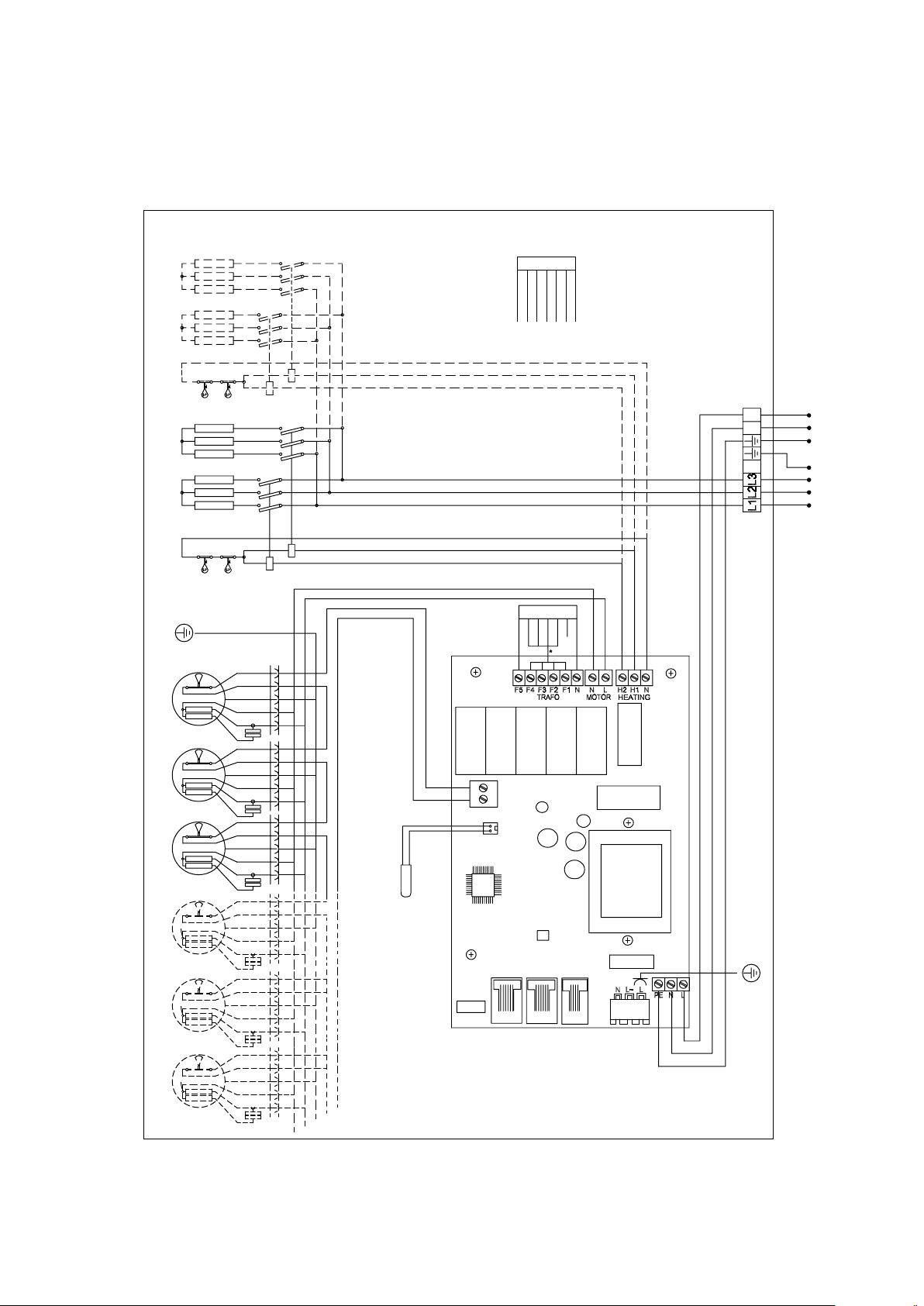
Electrical installation
The installation, which should be preceded by
an omnipolar switch with a contact separation
of at least 3 mm, should only be wired by a
competent electrician and in accordance with
the latest edition of IEE wiring regulations.
The control system is pre-installed in the air
curtain with an integrated control card. SIRe
is supplied pre-programmed with quick-fit
connections. Modular cables are connected to
the control board. The control card is always
placed at the top of vertical units.
See manual for SIRe.
Unit with water heating
The electrical connection may be done from
above or below, according to ordering key.
Control (230V~) should be connected to a
terminal block.
Unit with electrical heating
The electrical connection may be done from
above or below, according to ordering key.
Control (230V~) and power supply for heat
(400V3~) should be connected to a terminal
block. Modular cables for SIRe control board
should be drawn inside the unit when the
connection is made from the bottom. Bundle
the cables inside the unit to prevent that they
will be drawn into the fans or get in contact
with the heating elements.
The largest cable diameter for the terminal
block is 16 mm². The cable glands used must
meet the protection class requirements. In
the distribution board it is to be indicated
that ”the air curtains can be supplied from
more than one connection”.
See wiring diagrams.
Type Output
[kW]
All Control - 230V~ 1,5
SFS23E08 8,1 400V3~ 2,5
SFS30E12 11,7 400V3~ 4
SFS38E16 16,2 400V3~ 6
SFS56E23 23,4 400V3~ 10
Voltage
motor
[V]
Minimum
area
2
[mm
]
17
Page 13

GB
Number of motors
Models in the series have different number of
motors. In the production the motors will be
mounted starting from the bottom of the unit,
because it´s most important to protect at the
floor. Therefore it can be empty space above
the motors, at the models that have a smaller
number of motors.
Start-up (E)
When the unit is used for the first time or
after a long period of disuse, smoke or odour
may result from dust or dirt that has collected
on the element. This is completely normal
and disappears after a short time.
Connecting the water coil (W)
The installation must be carried out by an
authorised installer.
The water coil has copper tubes with
aluminium fins and is suitable for connection
to a closed water heating system. The heating
coil must not be connected to a mains
pressure water system or an open water
system.
Note that the unit shall be preceded by a
regulating valve, see Frico valve kit.
Water connection can be made from above
and below, according to the order key, via
DN25 (1"), internal thread connections.
When connection is made from below, the
connection is placed in altitude between the
first and second motor. Flexible hoses are
available as an accessory, see accessories
pages.
NOTE: Care must be taken when connecting
the pipes. Use a wrench or similar to hold the
air curtain connections to prevent straining
of the pipes and subsequent water leakage
during connection to water supply pipe-work.
The connections to the heating coil must be
equipped with shut off valves to allow problem
free removal. The battery is equipped with
bleed valves.
Filter (W)
The distance between the coil plates in
combination with the hole diameter of
the intake grille protects against dirt and
blockage. This normally makes a separate
filter unnecessary.
Service, repairs and maintenance
For all service, repair and maintenance first
carry out the following:
1. Disconnect the power.
2. The service hatch is opened by unscrew off
the screws in the side of the unit.
Maintenance
Unit with water heating:
The appliance filter should be cleaned
regularly to ensure the air curtain effect and
the heat emission from the device. How often
depends on local circumstances. A clogged
filter is not a risk, but the appliance function
can fail. Vacuum the intake grille regularly
from outside when dust is visible, for example
as a part of the cleaning routine.
All units:
Since fan motors and other components are
maintenance free, no maintenance other than
cleaning is necessary. The level of cleaning
can vary depending on local conditions.
Undertake cleaning at least twice a year. Inlet
and exhaust grilles, impeller and elements
can be vacuum cleaned or wiped using a
damp cloth. Use a brush when vacuuming
to prevent damaging sensitive parts. Avoid
the use of strong alkaline or acidic cleaning
agents.
Basic setting fan speed
The fan speed when the door is open is set
using the control. Note that the air flow
direction and fan speed may need fine
adjustment depending on the loading of the
door.
18
Page 14

GB
Overheating
The air curtain unit with electric heater is
equipped with an overheat protector. If it is
deployed due to overheating, reset as follows:
1. Disconnect the electricity with the fully
isolated switch.
2. Allow the electrical coil to cool.
3. Determine the cause of overheating and
rectify the fault.
4. Connect the air curtain again.
All motors are equipped with an integral
thermal safety cut-out. This will operate,
stopping the air curtain should the motor
temperature rise too high. The cut-out
will automatically reset when the motor
temperature has returned to within the
motor’s operating limits.
Temperature control
Temperature control of SIRe maintains the
exhaust temperature. If the temperature
should exceed anyway the overheating alarm
goes off. For more information see the manual
for SIRe.
Fan replacement
1. Determine which of the fans is not functioning.
2. Disconnect the cables to the relevant fan.
3. Remove the screws securing the fan and lift
the fan out.
4. Install the new fan as above in reverse order.
Replacing heating elements/heating
package (E)
1. Mark and disconnect the cables to the heating
elements/package
2. Remove the mounting screws securing the
heating elements/package in the unit and lift
the heaging elements/package out.
3. Install the new heating elements/package in
reverse order to the above.
Replacing the water coil (W)
1. Shut off the water supply to the unit.
2. Disconnect the connections to the water coil.
3. Remove the mounting screws securing the
coil in the unit and lift the coil out.
4. Install the new coil in reverse order to the
above.
Draining the water coil (W)
The drain valve is on the underside of the
coil. It can be accessed via the service hatch.
Trouble shooting
If the fans are not working or do not blow properly,
check the following:
• That the intake grille/filter is not dirty.
• Functions and settings of the SIRe control
system, see manual for SIRe.
If there is no heat, check the following:
• Functions and settings of the SIRe control
system, see manual for SIRe.
For units with electrical heating, also check the following:
• Power supply to electric heater coil; check
fuses and circuit-breaker (if any).
• That the overheat protection for the motors
has not been deployed.
For units with water coil, also check the following:
• That the water coil is air free.
• That there is enough water flow.
• That incoming water is heated enough.
If the fault cannot be rectified, please contact
a qualified service technician.
Residual current circuit breaker (E)
When the installation is protected by means
of a residual current circuit breaker, which
trips when the appliance is connected,
this may be due to moisture in the heating
element. When an appliance containing a
heater element has not been used for a long
period or stored in a damp environment,
moisture can enter the element.
This should not be seen as a fault, but is
simply rectified by connecting the appliance
to the main supply via a socket without a
safety cut-out, so that the moisture can be
eliminated from the element. The drying
time can vary from a few hours to a few days.
As a preventive measure, the unit should
occasionally be run for a short time when it is
not being used for extended periods of time.
19
Page 15

GB
Safety
• For all installations of electrically heated
products should a residual current circuit
breaker 300 mA for fire protection be used.
• Keep the areas around the air intake
and exhaust grilles free from possible
obstructions!
• The unit may have hot surfaces during
operation and when cooling down!
• The unit must not be fully or partially
covered with clothing, or similar materials,
as overheating can result in a fire risk! (E)
• Lifting equipment must be used to lift the
unit.
• This appliance can be used by children
aged from 8 years and above and persons
with reduced physical, sensory or mental
capabilities or lack of experience and
knowledge if they have been given
supervision or instruction concerning use of
the appliance in a safe way and understand
the hazards involved. Children shall not
play with the appliance. Cleaning and user
maintenance shall not be made by children
without supervision.
20
Page 16

Page 17

Page 18

Page 19

Main offi ce
Frico AB Tel: +46 31 336 86 00
Box 102
SE-433 22 Partille mailbox@frico.se
Sweden www.frico.se
For latest updated information and information
about your local contact: www.frico.se
Art.no 208030, 2017-01-03 HH/SÄ/SÅ
 Loading...