


Thermozone SF WL
SE
.... 10
GB
.... 13
SF WL
2
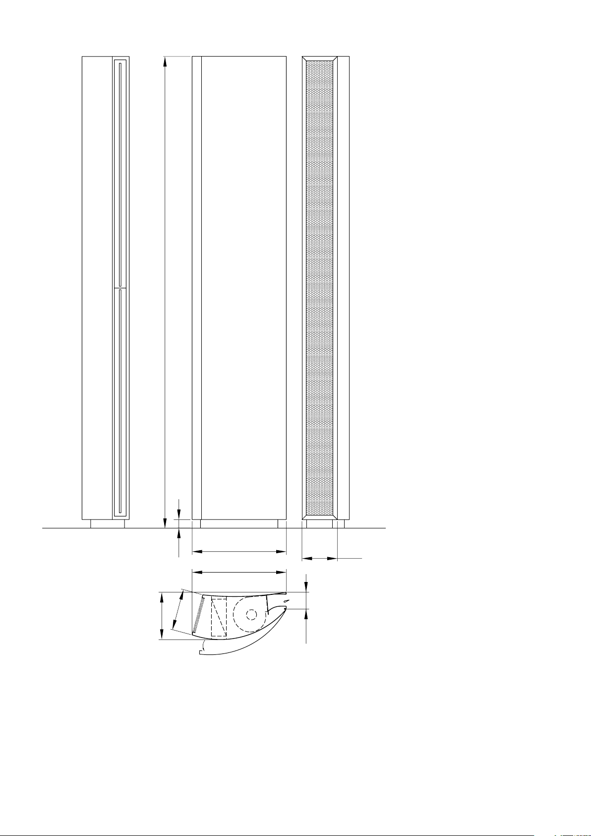
245
100
560
281
H
50
560
210
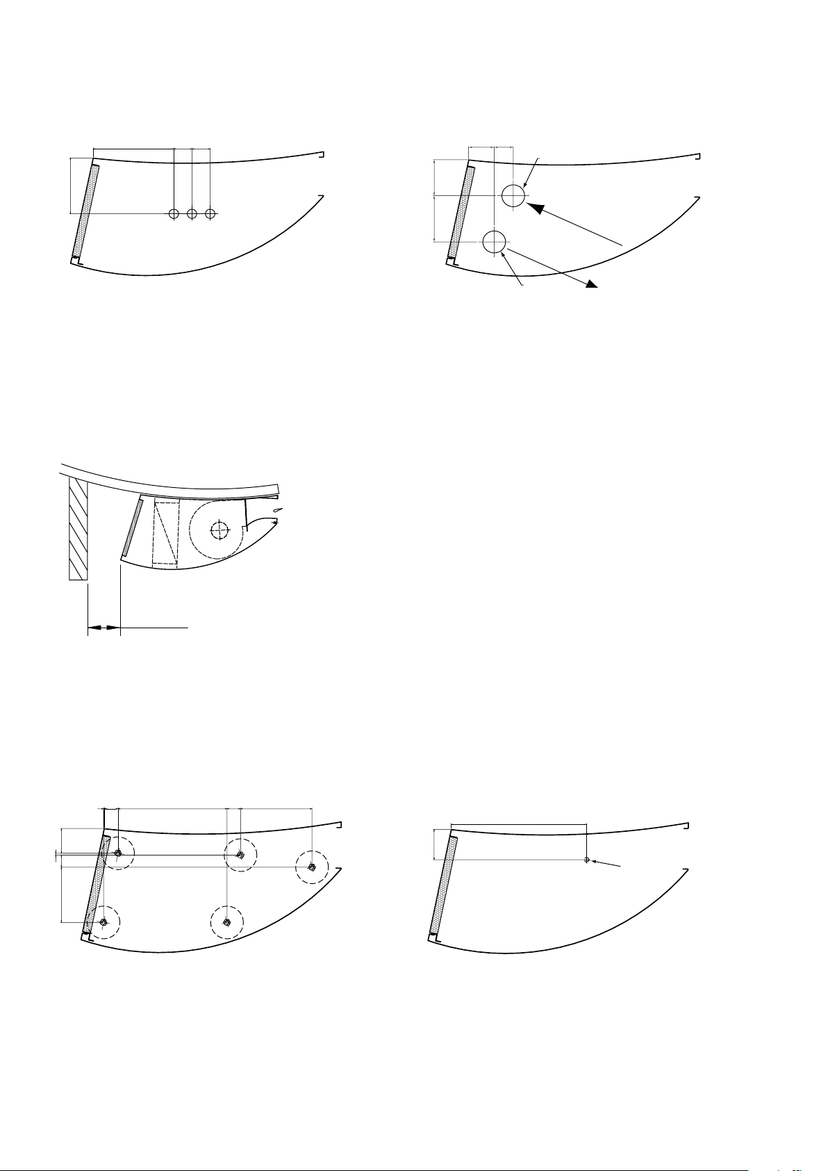
SF WL
3
min 120
30
233
29
153
53
118
1
4
26
290
65
M10 thread
178
40 40
126
42
82
106
56
Ø 50 mm
Connections
Electrical connections Water connections
Minimum mounting distance
Mounting
Positions of adjustable feet Securing the unit to the door
SF WL
4
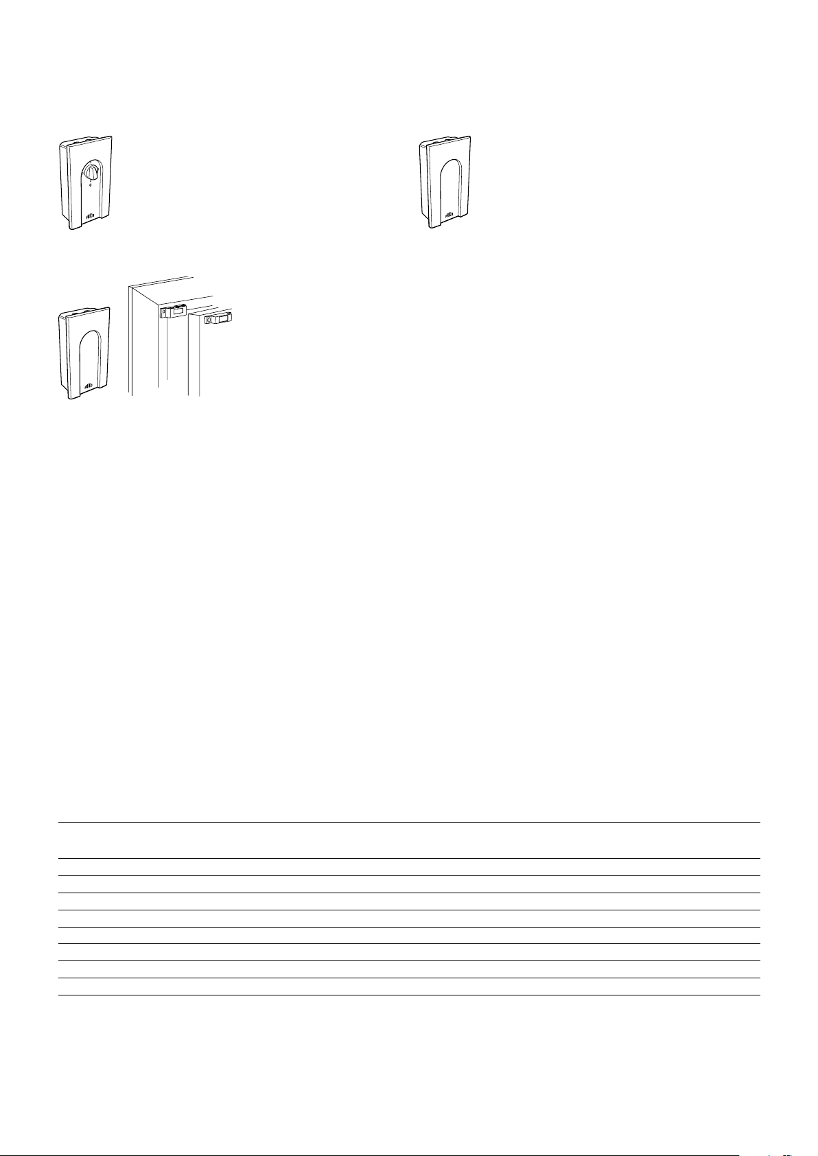
Accessories
MDC (MDCDC included)
RTI2CB30N
Accessories
Type E-nr
[SE]
CB30N Control Panel 87 511 83 672 69 85 54 610 91 155x87x50
MDC Magnetic door contact 87 511 98 672 65 64 155x87x43
RTI2 Electronic 2-step thermostat 85 811 44 54 910 90 150x80x43
JVF20 Balancing valve DN20 (3/4”)
JVF25 Balancing valve DN25 (1”)
AV25 Stop valve DN25 (1”)
VKSF Valve set integrated in the unit
FH1025 Flexible hoses 2 pcs x1m DN25 (1”)
RSK-nr
[SE]
EL-nr
[NO]
HxWxD
[mm]
SF WL
5
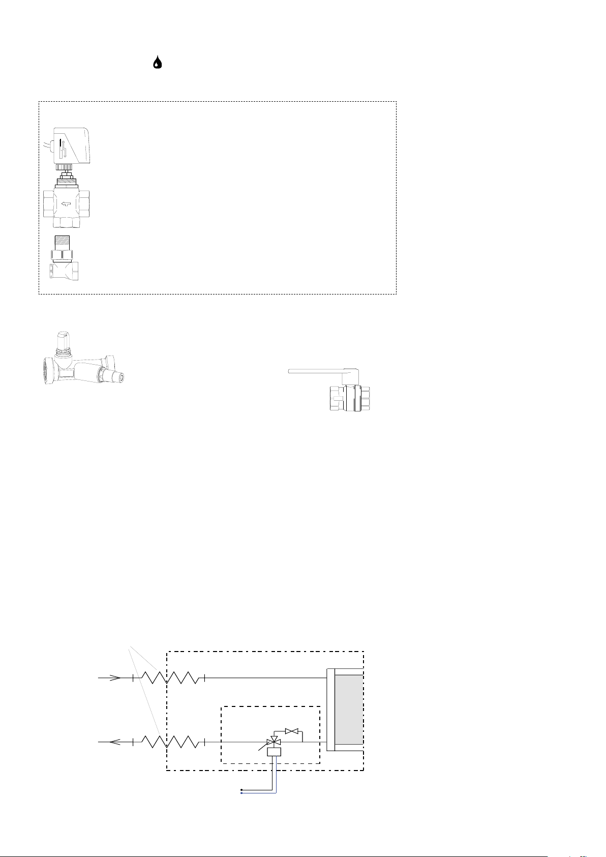
Water regulators
230V ~
Thermozone SF
TRV25
BPV10
SD20
DN25 (1")
DN25 (1")
FH1025
WKSF
Integrated in the unit: VKSF (accessory)
SD20
TRV20/25
BPV10
JVF20/25
AV25

SF WL
6
Wiring diagrams SF WL
Water regulation options
Water - Level 2
Closed contact = ON

SF WL
7
Output charts water
SF WL
Type Fan
position
SF18WL
(or SF1-2200WL)
SF24WL
(or SF2-2200WL)
SF36WL
(or SF3-2200WL)
SF45WL max 5400 49,2 42 0,60 44,5 45 0,54
Type Fan
SF18WL
(or SF1-2200WL)
SF24WL
(or SF2-2200WL)
SF36WL
(or SF3-2200WL)
SF45WL max 5400 36,4 35 0,88 31,7 38 0,77
max 1800 18,0 45 0,22 16,4 47 0,20
min 900 11,0 51 0,13 10,0 53 0,12
max 2400 23,5 44 0,29 21,3 46 0,26
min 1200 14,4 51 0,18 13,1 52 0,16
max 3600 37,9 46 0,46 34,3 48 0,42
min 1800 23,0 53 0,28 20,9 55 0,26
min 2700 30,9 49 0,38 28,0 51 0,34
position
max 1800 13,3 37 0,32 11,6 39 0,28
min 900 8,0 42 0,19 7,0 43 0,17
max 2400 17,3 36 0,42 15,1 39 0,37
min 1200 10,6 41 0,26 9,2 43 0,22
max 3600 27,7 38 0,67 24,2 40 0,59
min 1800 16,9 43 0,41 14,8 44 0,36
min 2700 22,7 40 0,55 19,8 42 0,48
Airflow
[m3/h]
Airflow
3
[m
/h]
Incoming / outgoing water temperature 80/60°C
Incoming air temp.= +15°C Incoming air temp. = +20°C
Output
[kW]
Incoming / outgoing water temperature 60/50°C
Incoming air temp.= +15°C Incoming air temp. = +20°C
Output
[kW]
Outgoing air
temp. [°C]
Outgoing air
temp. [°C]
Water flow
[l/s]
Water flow
[l/s]
Output
[kW]
Output
[kW]
Outgoing air
temp. [°C]
Outgoing air
temp. [°C]
Water
flow [l/s]
Water
flow [l/s]
Incoming / outgoing water temperature 60/40°C
Incoming air temp.= +15°C Incoming air temp. = +20°C
Type Fan
position
SF18WL
(or SF1-2200WL)
SF24WL
(or SF2-2200WL)
SF36WL
(or SF3-2200WL)
SF45WL max 5400 29,5 31 0,36 24,8 34 0,30
Type Fan
SF18WL
(or SF1-2200WL)
SF24WL
(or SF2-2200WL)
SF36WL
(or SF3-2200WL)
SF45WL max 5400 21,9 27 0,18 16,7 29 0,13
max 1800 10,9 33 0,13 9,2 35 0,11
min 900 6,8 37 0,08 5,7 39 0,07
max 2400 14,3 33 0,17 12,0 35 0,14
min 1200 8,9 37 0,11 7,5 39 0,09
max 3600 22,8 34 0,28 19,1 36 0,23
min 1800 14,0 38 0,17 11,9 40 0,14
min 2700 18,8 36 0,23 15,8 37 0,19
position
max 1800 8,2 29 0,07 6,1 30 0,05
min 900 4,5 30 0,04 2,7 29 0,02
max 2400 10,8 28 0,09 8,4 30 0,07
min 1200 6,8 32 0,06 4,6 32 0,04
max 3600 17,0 29 0,14 12,7 30 0,10
min 1800 9,3 30 0,08 5,1 29 0,04
min 2700 14,2 31 0,11 8,1 29 0,07
Airflow
3
[m
/h]
Airflow
3
[m
/h]
Output
[kW]
Incoming / outgoing water temperature 60/40°C
Incoming air temp.= +15°C Incoming air temp. = +20°C
Output
[kW]
Outgoing air
temp. [°C]
Outgoing air
temp. [°C]
Water flow [l/s] Output
[kW]
Water flow [l/s] Output
[kW]
Outgoing air
temp. [°C]
Outgoing air
temp. [°C]
Water
flow [l/s]
Water
flow [l/s]

SF WL
8
0,01
0,1
1,0
0,01
0,1
0,7
101,00,1
1
VR20
TVV20
VR25 / VKSF
TVV25
Pressure drop water
Water pressure drop over SF WL water coil
Pressure drop [kPa]
Water flow [m3/h]
Pressure drop [bar]
Water flow [l/s]
Water pressure drop over controls and valves
Pressure drop [kPa]
Water flow [m3/h]
0,7
Pressure drop [bar]
0,1
0,01
Water flow [l/s]
The pressure drop is calculated for an average temperature of 70 °C (PVV 80/60).
For other water temperatures, the pressure drop is multiplied by the factor K.
Average temp. water °C 40 50 60 70 80 90
K 1,10 1,06 1,03 1,00 0,97 0,93

SF WL
9
Technical specifications | Thermozone SF WL
Type Output
[kW]
*4
Airflow
[m3/h]
Sound
level*1
∆t*
[°C]
2,4
Voltage
[V]
Amperage
[A]
Length
[mm]
[dB(A)]
SF18WL (or SF1-2200WL)
SF24WL (or SF2-2200WL)
SF36WL (or SF3-2200WL)
18 1800 55 30 230V~ 2,52 2200
24 2400 56 29 230V~ 3,36 2200
38 3600 57 31 230V~ 4,48 2200
SF45WL 49 5400 57 27 230V~ 6,72 2200
*3
*3
*3
*3
SE
*1) Förhållanden: Avstånd till aggregat 5 meter. Riktningsfaktor: 2. Ekvivalent absorptionsarea: 200 m2.
*2) ∆t = temperaturhöjning på genomgående luft vid maximal värmeeffekt och högsta luftflöde.
*3) Aggregatet kan förlängas till max. 3900 mm (förlängning utan fläktar).
*4) Gäller vid vattentemperatur 80/60 °C, lufttemperatur in +15 °C.
GB
*1) Conditions: Distance to the unit 5 metres. Directional factor: 2. Equivalent absorption area: 200 m2.
*2) ∆t = temperature rise of passing air at maximum heat output and highest airflow.
*3) Extension possible up to 3900 mm (extension without fans).
*4) Applicable at water temperature 80/60 °C, air temperature +15 °C.
Weight
[kg]
11 0
11 6
122
11 0

SF WL
10
SE
Montage- och bruksanvisning
Allmänna anvisningar
Läs noga igenom denna bruksanvisning före
installation och användning. Spara manualen
för framtida bruk.
Garantin gäller endast om Frico montageoch bruksanvisning har följts och aggregaten
använts såsom däri är beskrivet.
Användningsområde
Luftridåaggregatet SF är avsett som skydd i
karuselldörrar och svängda skjutdörrar.
SF monteras vid sidan av dörren.
Funktion
Luften sugs in från apparatens sida och blåses
ut mot öppningen så att den skärmar av
portöppningen och minimerar värmeläckage
genom den. För bästa ridåverkan ska
aggregatet täcka hela öppningens höjd.
Gallret som riktar luften är justerbart och
vrids normalt något mot karuselldörren, så
att luftstrålen hindrar den inkommande kalla
luften.
Med varvtalsomkopplaren justeras
lufthastigheten till önskat luftflöde.
Luftridåns effektivitet beror på hur stor
belastningen är på den aktuella porten.
Observera att undertryck i lokalen
försämrar lufridåns effektivitet väsentligt.
Ventilationen bör därför vara balanserad!
Montering
Aggregatet monteras golvstående på
justerbara fötter som gör det möjligt att
kompensera för eventuella ojämnheter i
underlaget. Fötterna bultas fast i golvet och
täcks av en täckram. SF bör också förankras
i dörren. SF har en välvd design som gör
att den blir en integrerad del av dörren.
Aggregatet kan förlängas till maximalt 3900
mm (förlängning utan fläktar).
Aggregatet monteras på vänster sida om
öppningen (sett från insidan av lokalen).
Se till att serviceluckan är åtkomlig och kan
öppnas helt.
Se skisser s.2-3.
Elinstallation
Elanslutning skall utföras av behörig installatör och i enlighet med denna bruksanvisning
samt gällande föreskrifter.
1. Serviceluckan öppnas genom att lossa
skruvarna på aggregatets sida.
2. Apparaten ansluts via någon av de
genomföringar som finns på aggregatets
under- eller ovansida.
Flera olika alternativ för reglering av
motorernas varvtal och värmeeffekt finns
tillgängliga. Se kopplingsschema (s. 6).
Anslutning av vattenbatteri
Vattenbatteriet består av kopparrör med flänsar av aluminium och är avsett att användas
i ett slutet system. Batteriet får inte anslutas
till färskt eller syresatt vatten.
Inuti aggregatet finns anslutningar med
DN25 (1"), invändig gänga. Observera
att vid montering av rörkoppling skall
röranslutningarna i aggregatet hållas fast med
ett verktyg för att undvika skador och läckage.
Anslutningarna till batteriet ska förses
med avstängningsventiler för att möjliggöra
problemfri demontering. Den högsta punkten
på ledningarna som förser aggregatet
med vatten ska också utrustas med en
avluftningsventil. Installationen skall utföras
av behörig installatör.
Grundinställning varvtal
Fläkthastigheten ställs in med hjälp
av varvtalsregleringen. Observera att
utblåsriktning och varvtal kan behöva
finjusteras ytterligare beroende på portens
belastning.
Filter
Batteriets lamellavstånd i kombination med
håldiametern i insugsgallret skyddar mot
nedsmutsning och igensättning och gör ett
separat filter överflödigt.

SF WL
11
SE
Service, reparation och skötsel
Vid all service, reparation och underhåll gör
först enligt följande:
1. Bryt strömmen.
2. Serviceluckan öppnas genom att lossa
skruvarna på aggregatets sida.
Skötsel
Eftersom fläktarnas motorer och övriga
komponenter är underhållsfria krävs inget
annat underhåll än regelbunden rengöring,
hur ofta beror på de lokala omständigheterna,
dock minst två gånger per år. Insugs- och
utblåsgaller, fläkthjul och element kan
dammsugas eller torkas av med torr trasa. Vid
dammsugning använd borste för att inte skada
ömtåliga delar. Undvik starkt basiska eller
syrahaltiga rengöringsmedel.
Överhettning
Motorerna, i alla luftridåaggregaten, har
en inbyggd termokontakt till skydd mot
överhettning. Återställningen av denna sker
automatiskt då motorn har svalnat.
Fläktbyte
1. Undersök vilken av fläktarna som inte
fungerar.
2. Lossa kablarna till fläkten.
3. Lossa fläktens fästskruvar och lyft ut
fläkten.
4. Montera den nya fläkten enligt ovanstående
i omvänd ordning.
Felsökning
Om fläktarna inte blåser, kontrollera följande:
1. Att manöverspänning finns fram till
aggregatet; kontrollera säkringar,
arbetsbrytare, eventuellt kopplingsur som
startar/stoppar aggregatet.
2. Att eventuell varvtalsreglering är rätt
inställd.
3. Att gränslägesbrytaren fungerar (om sådan
är installerad).
4. Att motorernas överhettningsskydd inte har
löst ut.
5. Att insugsgallret inte är smutsigt.
Om det inte blåser varmt, kontrollera
följande:
1. Att varmvatten finns fram till
vattenbatteriet. (Kontrollera eventuell
cirkulationspump.)
2. Att värmebehov föreligger; kontrollera
termostatinställning och verklig temperatur.
3. Att insugsgallret inte är smutsigt.
Om felet ej kan avhjälpas, tag kontakt med
behörig servicetekniker.
Säkerhet
• Säkerställattområdetkringapparatens
insugs- och utblåsgaller hålls fritt från
material som kan hindra luftströmmen
genomapparaten!
• Apparatenharviddrifthetaytor!
Byte av vattenbatteri
1. Stäng av vattentillförseln till aggregatet.
2. Lossa anslutningarna till vattenbatteriet.
3. Lossa fästskruvarna som låser batteriet i
aggregatet och lyft ut batteriet.
4. Montera det nya batteriet enligt
ovanstående i omvänd ordning.
Tömning av vattenbatteriet
Tömningsventilen sitter undertill på
batteriet på anslutningssidan. Den nås via
serviceluckan.
Tekniska data finns på s. 9.

SF WL
12
SE
Vattenreglering
VKSF, trevägsventil med ställdon och by-passventil kan byggas in i
aggregatet.
Om trevägsventilen (TRV25) är stängd,
passerar ett lågt flöde genom by-passventilen
(BPV10) för att det alltid ska finnas varmt
vatten i värmebatteriet. Detta för att ge en
snabb värmetillförsel t.ex. när en port öppnas
samt för ett visst frysskydd. Ställdonet (SD20)
reglerar värmetillförseln on/off.
TRV25 har DN25 (1”). By-passventilen har
DN10 (3/8”).
SD20, ställdon
on/off 230V~ (mjukstängande)
För reglering av värmetillförseln. Arbetar
on/off. Cykel-tiden mellan stängt och öppet
på fem sekunder förhindrar tryckslag i
rörsystemet. IP40.
AV25, avstängningsventil
Består av en kulventil som antingen är öppen
eller stängd och används för att kunna stänga
av flödet, t.ex. vid service.
JVF20/25, injusteringsventil
Med injusteringsventilen kan flödet finjusteras
manuellt eller stängas av helt. Det injusterade
vattenflödet kan avläsas direkt på ventilen.
JVF20 har kv-värde 3,5 och JVF25 har kvvärde 5,5.
Komplettera med lämplig termostat.

SF WL
13
Assembly and operating instructions
GB
General instructions
Read these instructions carefully before
installation and use. Keep this manual for
future reference.
The guarantee is only valid if the
Thermozone units are used in the manner
intended by the manufacturer and in
accordance with the Frico installation and
maintenance instructions.
Application area
The SF air curtain unit is intended for
installation in curved doorways.
SF is installed to the side of the entrance.
Operation
Air is drawn in at the side of the unit and
blown out towards the entrance so that it
shields the door opening and minimizes heat
loss. To achieve the optimum curtain effect
the unit must extend the full height of the
door opening.
The grille for directing exhaust air is
adjustable and is normally angled towards the
curved doorway to achieve the best protection
against incoming cold air.
The airflow can be adjusted by use of the fan
speed selector.
The efficiency of the air curtain(s) depends
on the air temperature, pressure differences
across the doorway and any wind pressure.
NOTE!Negativepressureinthebuilding
considerably reduces the efficiency of the air
curtain. The ventilation should therefore be
balanced!
Installation
The unit is installed as floor standing on
adjustable feet that make it possible to
compensate for possible irregularities in the
floor. The feet are bolted to the floor and
covered by a covering edge. SF is mounted
to the left of the door seen from inside the
building and should also be secured to the
door. SF has a curved design that integrates
neatly with the door. Extension is possible up
to 3900 mm (extension without fans).
Ensure that the service hatch is accessible
and can be fully opened.
See sketches p.2-3.
Electrical installation
Electrical connection may only be carried
out by an authorized electrician, and in
accordance with these instructions and the
applicable regulations.
1. The service hatch is opened by slackening
off the screws in the side of the unit.
2. The unit is connected via one of the cable
glands in the upper or lower side of the
unit.
Different combinations for controlling fan
speed are available. See wiring diagram (p. 6).
Water coil connection
The water coil has copper tubes with
aluminium fins and is suitable for connection
to a closed water heating system. The heating
coil must not be connected to a mains
pressure water system or an open water
system.
The water pipes are connected to the
terminals with DN25 (1"), internal thread on
the inside of the unit. Use a wrench or similar
to hold the air curtain connections to prevent
straining the pipes and subsequent water
leakage during connection to water supply
pipe-work.
The connections to the heating coil must be
equipped with shut off valves to allow problem
free removal. The highest point of the pipes
supplying the unit with water must also be
fitted with a bleed valve. The installation must
be carried out by an authorised installer.
Basic setting fan speed
The fan speed is set using the speed control.
Note that the air flow direction and speed
may need fine adjustment depending on the
loading of the door.

SF WL
14
GB
Filter
The heat coil plate distance in combination
with the hole diameter of the intake grille
protects against dirt and blockage and makes
a separate filter unnecessary.
Service, repairs and maintenance
For all service, repair and maintenance first
carry out the following:
1. Disconnect the power supply.
2. The service hatch is opened by slackening
off the screws in the side of the unit.
Maintenance
Since fan motors and other components are
maintenance free, no maintenance other than
cleaning is necessary, this can vary depending
on local conditions. Undertake cleaning
at least twice a year. Grille, impeller and
elements can be vacuum cleaned or wiped
using a damp cloth. Avoid the use of strong
alkaline or acidic cleaning agents.
Overheating
All motors are equipped with an integral
thermal safety cut-out. This will operate,
stopping the air curtain should the motor
temperature rise too high. The cut-out
will automatically reset when the motor
temperature has returned to within the
motor's operating limits.
Fan replacement
1. Determine which of the fans is not
functioning.
2. Disconnect the cables to the relevant fan.
3. Remove the screws securing the fan and lift
the fan out.
4. Install the new fan in reverse order to the
above.
Draining the water coil
The drain valve is on the underside of the coil
on the connector side. It can be accessed via
the service hatch.
Trouble shooting
If the fans do not run, check the following:
1. Operating power supply to the unit; check
fuses, circuit-breaker, time switch (if any)
that starts and stops the unit.
2. That the air flow selector is correctly set.
3. That the position limit switch is working (if
installed).
4. That the overheat protection for the motors
has not been deployed.
5. That the intake grille is not dirty.
If there is no heat, check the following:
1. That there is hot water to the water
coil. (Check the circulation pump - if
applicable.)
2. That the heat demand exists; check
thermostat settings and actual temperature.
3. That the intake grille is not dirty.
If the fault cannot be rectified, please contact
a qualified service technician.
Safety
• Keeptheareasaroundtheairintake
andexhaustgrillesfreefrompossible
obstructions!
• Duringoperationthesurfacesoftheunit
are hot!
Technical data is on page 9.
Replacing the water coil
1. Shut off the water supply to the unit.
2. Disconnect the connections for the water
coil.
3. Remove the mounting screws securing the
coil in the unit and lift the coil out.
4. Install the new coil in reverse order to the
above.

SF WL
15
GB
Water control
VKSF, three-way motor valve with actuator and by-pass valve can be
integrated in the unit.
If the three way valve (TRV20/25) is closed,
a low flow passes through the by-pass valve
(BPV10) so that there is always warm water
in the water coil. This is to provide quick
heat supply when a door is opened but also to
provide a degree of frost protection. Actuator
(SD20) controls the heat supply on/off.
TRV25 is DN25 (1”). The by-pass valve is
DN10 (3/8").
SD20, actuator
on/off 230V~ (soft close)
For control of the water supply. Works on/off.
A 5 second cycle of opening and closing of the
valve prevents sudden pressure changes in
the pipe system. IP40.
AV25, stop valve
The stop valve consists of a ball valve which
is either open or closed and is used to shut off
the flow, when servicing for example.
JVF20/25, adjustment valve
The adjustment valve can be used to finely
adjust or shut off the water flow manually.
The adjusted water flow can be read directly
off the valve. JVF20 has a kv value of 3.5 and
JVF25 has a kv value of 5.5.
To be supplemented with a suitable
thermostat for control.

Main office
Frico AB Tel: +46 31 336 86 00
Box 102 Fax: +46 31 26 28 25
SE-433 22 Partille mailbox@frico.se
Sweden www.frico.se
Norway
Frico AS Tel: +47 23 37 19 00
P.B 82 Alnabru Fax: +47 23 37 19 10
NO-0614 Oslo mailbox@frico.no
Norway www.frico.no
France
Frico SAS Tel: +33 4 72 42 99 42
53 avenue Carnot Fax: +33 4 72 42 99 49
69250 Neuville sur Saône info@frico.fr
France www.frico.fr
Spain
Frico repr. office in Spain Tel: +34 91 887 60 00
C/. Cabeza de hierro, 39 Fax: +34 91 887 60 00
ES-28880 Meco mailbox@frico.com.es
Spain www.frico.se
United Kingdom
Frico Limited Tel: +44 (0)121 322 0854
72 Cheston Road Fax: +44 (0)121 322 0858
B7 5EJ info.uk@frico.se
UK-Birmingham www.frico.co.uk
United Kingdom
Russia
Frico repr. office in Russia Tel: +7 495 238 63 20
Lavrov per. 6 +7 495 676 44 48
RU-109044 Moscow Fax: +7 495 676 44 48
Russia frico@trankm.ru
www.frico.se
China
Frico repr. office in China Tel: +86 21 62569900
Rm 702, Mod. Comm. Build. Fax:+86 21 62554747
201, New Jin qiao Rd frico@sohu.com
201206 Shanghai www.frico.com.cn
P.R. China
Austria
Frico GmbH Tel: +43 1 616 24 40-0
Kolpingstraße 14
1232 Wien office@fricogmbh.at
Austria www.fricogmbh.at
For latest updated information, see: www.frico.se
Switzerland
Gutekunst AG Tel: 061 706 96 26 (nat)
Baselstrasse 22 Fax: 061 706 96 20 (nat)
CH-4144 Arlesheim info@gutekunst-ag.ch
Switzerland www.gutekunst-ag.ch
20080509 BS
 Loading...