

Original instructions
Scand
EN
NL
FI
.... 10
....34
.... 60
SE
ES
DK
.... 14
.... 39
....65
NO
IT
.... 19
.... 44
FR
PL
.... 24
.... 49
DE
RU
.... 29
.... 54

Scand
EN
SE
NO
FR
DE
The introduction pages consist mainly of pictures. For translation of the English
texts used, see the respective language pages.
Introduktionssidorna består huvudsakligen av bilder. För översättning av de
engelska texter som används, se respektive språksidor.
Introduksjonssidene består hovedsakelig av bilder. For oversettelse av de
engelske tekstene, se de respektive språksidene
Les pages de présentation contiennent principalement des images. Consulter la
page correspondant à la langue souhaitée.
Die Einleitungsseiten bestehen hauptsächlich aus Bildern. Für die Übersetzung
der verwendeten Texte in englischer Sprache, siehe die entsprechenden
Sprachseiten.
NL
ES
IT
PL
RU
De inleidende pagina's bevatten hoofdzakelijk afbeeldingen. Voor een vertaling
van de gebruikte Engelse teksten, zie de pagina's van de resp. taal.
Las páginas introductorias contienen básicamente imágenes. Consulte la
traducción de los textos en inglés que las acompañan en las páginas del idioma
correspondiente.
Le pagine introduttive contengono prevalentemente immagini. Per le
traduzioni dei testi scritti in inglese, vedere le pagine nelle diverse lingue.
Początkowe strony zawierają głównie rysunki. Tłumaczenie wykorzystanych
tekstów angielskich znajduje się na odpowiednich stronach językowych.
Страницы в начале Инструкции состоят в основном из рисунков, схем и
таблиц. Перевод встречающегося там текста приведен в разделе RU.
2
FI
DK
Esittelysivut koostuvat lähinnä kuvista. Suvuilla olevien enlanninkielisten
sanojen käännökset löytyvät ko. kielisivuilta.
Introduktionssiderne består hovedsageligt af billeder. For oversættelse af de
engelske tekster, se siderne for de respektive sprog.
Scand
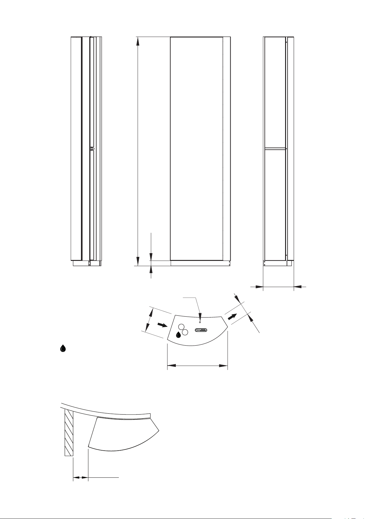
247
2200
50
296
2200
Inside thread : 1", DN25
Minimum distance
50
296
M8
116
581
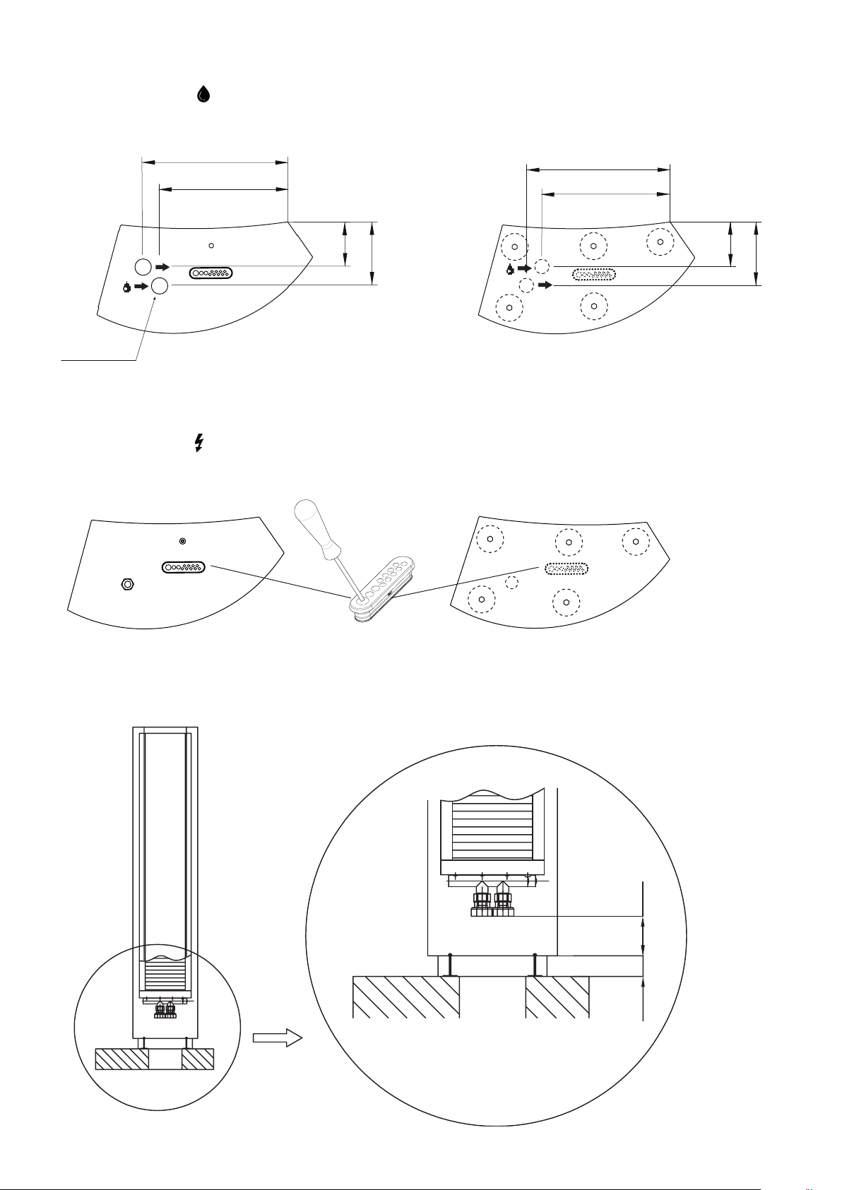
min 120
3
380
Scand
Connections W
Top view of the top (connections from above) Top view of the bottom (connections from below)
380
339
339
Ø48 (2x)
11 8
168
Inside thread : 1", DN25
11 8
Connections E
Top view of the top (connections from above) Top view of the bottom (connections from below)
168
Distance water connections - end
50 200
4
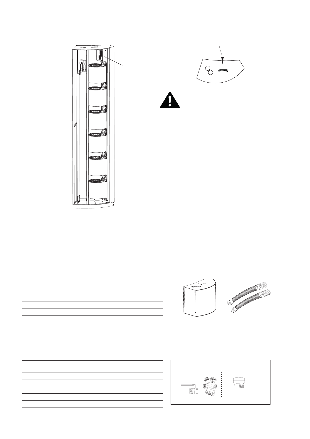
Open unit
M8
Scand
PC board FC
Frico Control
Note! The air curtain must
always be secured at the top.
PC board FC is integrated within the air curtain at delivery.
Accessories
Item
number
FE10129
330955
.
Type
SFSEH 100-1000 mm
FH1025 DN25, 1”, 1000 mm
Valve systems
Item
number
238293
238294
238295
238296
238297
See separate manual.
Type Dimension
valves
VPFC15LF DN15 0,012-0,068
VPFC15NF DN15 0,024-0,13
VPFC20 DN20 0,058-0,32
VPFC25 DN25 0,10-0,60
VPFC32 DN32 0,22-1,03
Flow range
[l/s]
SFSEH FH1025
VPFC
VKF
SDM
5

Scand
Control systems
The air curtain must be supplemented with a control system.
FCDA - FC Direct FCSA - FC Smart
FCBC05FCDCFCCF
FCBC10FCDCFCCF
FCLAP
FCPA - FC Pro FCBA - FC Building
Item
number
74684
74685
74686
74687
FCBC10FCDCFCCF
Type Name Dimensions
FCDA
FCSA
FCPA
FCBA
FCLAP
FC Direct 89x89x26 mm (FCCF)
FC Smart 89x89x26 mm (FCCF)
FC Pro 89x89x26 mm (FCCF)
FC Building 89x89x26 mm (FCCF)
FCTXRF
Accessories
FCBC10FCDCFCCF
FCBAP
FCRTX
FCSC10
Item
number
74694
74695
74699
74702
17495
74718
74719
74720
74721
74722
74703
Type Dimensions
FCRTX
FCOTX
FCLAP
FCWTA SFFEC W
FCDC
FCBC05 5 m
FCBC10 10 m
FCBC25 25 m
FCSC10 10 m
FCSC25 25 m
FCTXRF for FC Smart, FC Pro
See separate manual for FC.
FCOTX
FCSC10
39x39x23 mm
39x39x23 mm
89x89x26 mm
89x89x26 mm
FCLAP
FCBC10
FCBC05/10/25
FCSC10/25
FCDCFCWTA
FCTXRF
6

Scand
Technical specications
3 Electrical heat - SFFEC E (IP20)
Item
number
FE10240 SFFEC4E16 5,4/11/16 1850/3600 26/13 82 48/66 4,1 400V3~/24 70
FE10242 SFFEC6E24 7,8/16/24 2300/4700 30/15 83 50/67 6 400V3~/34 75
Type Output
steps
[kW]
Airow*1
[m3/h]
2 Water heat - SFFEC WH (IP20)
Item
number
FE10241 SFFEC4WL 21 36 1650/3300 24/19 40/32 4,4 80 47/64 4,1 70
FE10243 SFFEC6WL 26 44 2200/4600 22/17 37/28 4,4 81 47/65 6 75
Voltage motor: 230V~
Height*7: 2200 mm
Type Output*5
[kW]
Output*6
[kW]
*4
∆t
[°C]
Airow*1
[m3/h]
Sound
power*2
[dB(A)]
*4,5
∆t
[°C]
∆t
[°C]
*4,6
Sound
pressure*3
[dB(A)]
Water
volume
[l]
Amperage
motor
[A]
Sound
power*2
[dB(A)]
Voltage [V]
Amperage
[A](heat)
Sound
pressure*3
[dB(A)]
Weight
[kg]
Amp.
motor
[A]
Weight
[kg]
1
*
) Low/high airow (2V/10V).
*2) Sound power (LWA) measurements according to ISO 27327-2: 2014, Installation type E.
*3) Sound pressure (LpA). Conditions: Distance to the unit 5 metres. Directional factor: 2. Equivalent
absorption area: 200 m². At low/high airow (2V/10V).
*4) ∆t = temperature rise of passing air at maximum heat output and low/high airow (2V/10V).
*5) Applicable at water temperature 60/40 °C, air temperature, in +18 °C.
*6) Applicable at water temperature 80/60 °C, air temperature, in +18 °C.
*7) Standard height. Max. height 3000 mm (extension without fans).
5,6
*
) See www.frico.net for additional calculations.
Product key
Type - Connection position - Total height - Material / Colour
Example: SFFEC4WL - A - 2800 - P
Type See Technical specications.
Connection position*
Total height
A = from above
B = from below
Min. height 2200 mm.
Max height 3000 mm. Extension without fans
A
P = Polished stainless steel
B = Brushed stainless steel
Material / Colour
MP = Mirror polished stainless steel
State RAL code = Powder coating RAL
State NCS code = Powder coating NCS
B
Contact Frico before ordering for more information about the product and special adaptations.
EN Connection position*
SE Anslutningsposition
NO Tilkoblingsposisjon
DE Position der Anschlüsse
RU Место подключений
FR Position du raccord
ES Posición de la conexión
NL Positie aansluitingen
PL Położenie złączy
IT Posizione di collegamento
DK Tilslutningsposition
7

SFFEC E
Scand
252999
SFFEC 4E1 6
SFFEC 6E2 4
K1
K2
TS 3
TS 4
N
L3L2L1 NL3L2L1
400V 3~
K1
TS 2
TS 1
4 Motors
6 Motors
K2
Mo t o r
Trafo
N
L PE
230V IN
H1 H2N
H eating
PE
Inle t s ens or
Outlet s en so r
A1 A2
GND
ON
Terminati on
OFF
HI
+12V
GND
BUS 1 B US 2
B1 B2 D1 D2
GND
LO
GND
+12V
Mo t o r
Se n so r
GND
0-10V
PWM
Alarm
I1 I2 O1 O2
N
L
FCBASEPCB REA
HI
LO
SFFEC 4E16 :
SFFEC 6E24 :
Wiring diagrams for control system in the FC manual.
8
230V~

SFFEC W
Scand
SFFEC4WL:
SFFEC6WL:
4 Motors
6 Motors
GND
BUS 1 BUS 2
+12V
HI
LO
GND
+12V
HI
LO
Inlet sensor
Outlet sensor
ON
OFF
GND
A1 A2
Termination
GND
B1B2 D1 D2
Sensor
I1 I2 O1 O2
Alarm
FCBASEPCB RW
PWM
0-10V
Motor
GND
Act uator 230V 230V I N
N
L
L
N
PE
PE
Trafo
230V~
Wiring diagrams for control system in the FC manual.
N
L
Motor
SFFEC4WL
SFFEC6WL
252998
9

EN
Scand
Installation and operating instructions
General Instructions
Read these instructions carefully prior to
installation and use. Keep this manual for
future reference.
The product may only be used as set out in
the assembly and operating instructions. The
guarantee is only valid should the product be used
in the manner intended and in accordance with
the instructions.
Application
Scand is a vertical air curtain specially designed
for revolving doors, with a curved design that
integrates neatly with the door. The air curtain
is available with electrical heating and with
water heating.
Protection class: IP20.
Operation
Air is drawn in at the side of the unit and blown
out against the entrance, so that it shields the
door opening and minimizes heat loss.
The grille for directing exhaust air is
adjustable and is normally angled towards the
revolving door to achieve the best protection
against incoming cold air.
The eciency of the air curtain depends
on the air temperature, pressure differences
across the doorway and any wind pressure.
NOTE! Negative pressure in the building
considerably reduces the eciency of the air
curtain. The ventilation should therefore be
balanced.
Mounting
The air curtain is vertically mounted to the
left of the door seen from inside. Air curtains
for installation to the right can be specially
ordered. The unit has a curved design which
makes it an integrated part of the door.
Standard length is 2200 mm. Lengths up to
3 m can be ordered according to the product
key (extension without fans). Extension hoods,
for heights up to 4 m , are available as an
accessory.
The air curtain is installed on adjustable feet
which makes it possible to compensate for
any surface undulations. The feet are attached
to the oor with fasteners appropriate to the
surface and covered by a frame. Fasteners are
not included.
The air curtain must always be secured at the
top. The M8 press nut on the top of the unit is
used for this, see gure.
The product must be mounted in such a way
to allow future service and maintenance.
When mounting a product in stainless steel,
the protective plastic shall remain on the
product. The plastic is removed only when
mounting and installation are completed. Be
careful to not damage the surfaces.
Electrical installation
The installation, which should be preceded by
an isolator switch with a contact separation
of at least 3 mm, should only be wired by a
competent electrician and in accordance with
the latest edition of IEE wiring regulations.
The air curtain has an integrated PC board
which is connected to the selected external
control system FC. FC must be ordered
separately. FC is supplied pre-programmed.
Communication- and sensor cables are
connected to the PC board.
Should more than one air curtain be
controlled by a single FC, an additional
communication cable FCBC per unit will be
required. See manual for FC.
Control is supplied by 230V~ to the PC board.
The PC board is placed in the top of the unit
and is accessed via cable glands on the top
or bottom of the unit. Pierce the gland with a
screwdriver before entering the cable. Cables to
the PC board should be routed through the unit
when the connection is made from the bottom.
Bundle the cables inside the unit to prevent
that they will be drawn into the fans or get in
contact with the heating elements.
For units with electrical heating, the power
supply for heating (400V3~) is connected to
the terminal block. The electrical connection
may be done from above or below, according
to ordering key. Connections made from
below the unit must be prepared in the oor
according to the drawing.
The largest cable diameter for the terminal
block is 16 mm². The cable glands used must
meet the protection class requirements. In the
distribution board, it is to be indicated that ”the
air curtains can be supplied from more than
one connection”.
Type Output Voltage Minimum
Control
SFFEC4E16 16 400V3~ 6
SFFEC6E24 24 400V3~ 10
*) Dimensioning of external wiring shall comply with
applicable regulations and local deviations may occur.
[kW]
0 230V~ 1,5
[V]
area*
[mm2]
10

Scand
EN
Start-up (E)
When the unit is used for the rst time or after
a long period of non-use, smoke or an odour
may result from dust or dirt which has collected
on the element. This is completely normal and
disappears after a short time.
Connecting the water coil (W)
The installation must be carried out by an
authorised installer.
The water coil has copper tubes with
aluminium ns and is suitable for connection
to a closed water heating system. The heating
coil must not be connected to a mains pressure
water system or an open water system.
Note that the unit shall be preceded by a
regulating valve, see Frico valve kit.
Valves must be installed outside the unit.
Note that the actuator needs power supply and
control signal from the integrated PC board.
The water coil is connected on the top or the
bottom of the unit via connections DN25 (1’’),
internal thread. See product key.
Connections made from below the unit must
be prepared in the oor according to the
drawing. Note the distance between the water
connections and the end of the unit. See gure.
Flexible hoses are available as accessories.
NOTE: Care must be taken when connecting
the pipes. Use a pipe wrench or a similar
tool to grip the air curtain connections to
prevent straining of the pipes and subsequent
water leakage during connection to the water
supply pipe-work.
The connections to the heating coil must be
equipped with shut off valves to allow trouble-
free removal.
The coil is equipped with air valves.
Adjustment of the air curtain and airow
The direction and speed of the airow should
be adjusted considering the load on the
opening. Pressure forces affect the airstream
and force it inwards towards the premises
(when the premises are heated and the
outdoor air is cold).
The airstream should, therefore, be directed
outwards to withstand the load. Generally
speaking, the higher the load, the greater the
angle required.
Protection of the exposed area just above the
oor is essential, motors are placed from the
bottom up. The airow can therefore be slighlty
less at the top of unit.
Basic setting fan speed
The fan speed when the door is open is
set using the control. Note that the airow
direction and the fan speed may need ne
adjustment depending on the loading of the
door.
Filter (W)
The distance between the coil plates in
combination with the hole diameter of
the intake grille protects against dirt and
blockage. This normally makes a separate lter
unnecessary.
Service, repairs and maintenance
For all service, repair and maintenance rst
carry out the following:
1. Disconnect the power supply.
2. The service hatch is opened by removing the
screws on the side of the unit.
Maintenance
Since fan motors and other components are
maintenance-free, no maintenance other than
cleaning is necessary. The level of cleaning can
vary depending on local conditions. Undertake
cleaning at least twice a year. Inlet and exhaust
grilles, impeller and elements can be vacuum
cleaned or wiped using a damp cloth. Use a
brush when vacuuming to prevent damaging
sensitive parts. Avoid the use of strong alkaline
or acidic cleaning agents.
Vacuum the intake grille regularly from outside
when dust is visible, for example as a part of
the cleaning routine.
Temperature control
Temperature control of FC maintains the
exhaust temperature. Should the temperature
exceed the preset value, the overheating alarm
will activate. For more information see the FC
manual.
Overheating
The air curtain unit with electrical heating is
equipped with an overheat protection. If it is
deployed due to overheating, reset as follows:
1. Disconnect the power supply with the isolator
switch.
2. Allow the electrical coil to cool.
3. Determine the cause of overheating and
rectify the fault.
4. Reconnect the unit.
11

EN
Scand
Replacing heating elements/heating
package (E)
1. Mark and disconnect the cables to the
heating elements/package.
2. Remove the mounting screws securing the
heating elements/package in the unit and lift
the heating elements/package out.
3. Install the new heating elements/package in
reverse order to the above.
Replacing the water coil (W)
1. Shut off the water supply to the unit.
2. Disconnect the connections to the water coil.
3. Remove the mounting screws securing the
coil in the unit and lift out.
4. Install the new coil in reverse order to the
above.
Safety cut-out
All motors are equipped with an integrated
safety cut-out. This will operate, stopping the
air curtain should the motor temperature rise
excessively or the electronics fail or overheat.
The cut-out will automatically reset when the
motor temperature has returned to within the
motor’s operating limits. Failure or damage to
electronics components may require repair or
replacement of such components or the entire
product.
Fan replacement
1. Determine which of the fans is not
functioning.
2. Disconnect the cables from the relevant fan.
3. Remove the screws securing the fan and lift
the fan out.
4. Install the new fan as above in reverse order.
Replacing the PC board
1. The PC board is located in the terminal box.
2. Mark and disconnect the cables to the PC
board.
3. Unhatch the board from its PCB snap-in
spacers and lift out.
4. Install the new PC board as above in reverse
order.
Troubleshooting
If the fans are not running or do not perform
properly, check the following:
• The power supply.
• That the intake grille/lter is not dirty.
• That the motor's safety cut-out has not been
deployed.
• Functions and settings of the FC control
system, see the FC manual.
If there is no heat, check the following:
• Functions and settings of the FC control
system, see the FC manual.
For units with electrical heating, also check the
following:
• Power supply to electric heater coil; check
fuses and circuit-breaker (if any).
• That the overheat protection has not been
deployed.
For units with a water coil, also check the
following:
• That the water coil is air free.
• That there is sucient water ow and
pressure.
• That incoming water is heated adequately.
If the fault cannot be rectied, please contact a
qualied service technician.
Residual current circuit breaker (E)
When the installation is protected by means of
a residual current circuit breaker, which trips
when the appliance is connected, this may be
due to moisture in the heating element. When
an appliance containing a heater element has
not been used for a long period or stored in
a damp environment, moisture can enter the
element.
This should not be seen as a fault, but is
simply rectied by connecting the appliance to
the main supply via a socket without a safety
cut-out so that the moisture can be eliminated
from the element. The drying time can vary
from a few hours to a few days. As a preventive
measure, the unit should occasionally be run
for a short time when it is not being used for
extended periods of time.
12

Scand
Packaging
Packaging materials are chosen with
consideration to the environment and are
therefore recyclable.
Handling of product at end of working
life
This product may contain substances necessary
for the functionality of the product but
potentially dangerous for the environment. The
product should not be disposed of mixed with
general household waste but delivered to a
designated collection point for environmental
recycling. Please contact the local authority
for further details of your nearest designated
collection point.
Safety
• For all installations of electrically heated
products a residual current circuit breaker
300 mA for re protection should be used.
• Keep the areas around the air intake and
exhaust grilles free from possible obstructions!
• The unit must not be fully or partially covered as
overheating can result in a re risk!
• Lifting equipment must be used to lift the unit.
• This appliance can be used by children aged
from 8 years and above and persons with
reduced physical, sensory or mental capabilities
or lack of experience and knowledge if they
have been given supervision or instruction
concerning use of the appliance in a safe way
and understand the hazards involved. Children
shall not play with the appliance. Cleaning and
user maintenance shall not be made by children
without supervision.
• Children of less than 3 years should be kept
away unless continuously supervised.
• Children aged from 3 years and less than 8
years shall only switch on/off the appliance
provided that it has been placed or installed
in its intended normal operating position and
they have been given supervision or instruction
concerning use of the appliance in a safe way
and understand the hazards involved.
• Children aged from 3 years and less than 8
years shall not plug in, regulate and clean the
appliance or perform user maintenance.
EN
CAUTION — Some parts of this product can
become very hot and cause burns. Particular
attention has to be given where children and
vulnerable people are present.
13

Main offi ce
Frico AB Tel: +46 31 336 86 00
Industrivägen 41
SE-433 61 Sävedalen mailbox@frico.se
Sweden www.frico.net
For latest updated information and information
about your local contact: www.frico.net.
Art.no 253011, 2021-02-16 CH
 Loading...