

Original instructions
RDS
SE
.... 15
GB
.... 18

RDS
L
Top view
X
Y
W
R
L
[mm]
RDS23 1000
RDS29 1000
RDS38 1500
RDS56 2000
RDS65 2500
Side view
520
Min. 800
220
270
125
Z + 265
70
Z + 240
Z
H
115
2
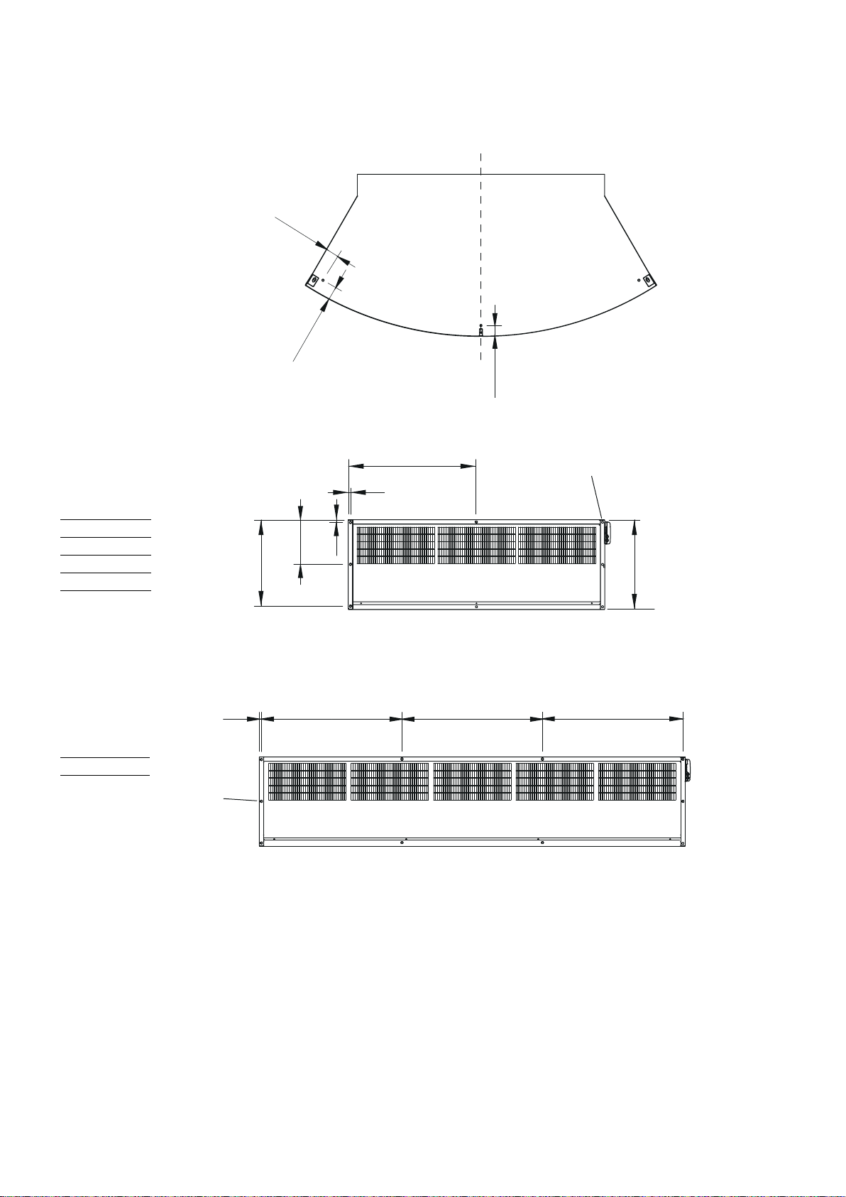
Suspended from ceiling
RDS
ca 75
ca 80
ca 65
RDS23E/WL
RDS29E/WL
RDS38E/WL
RDS56E/WL
RDS65E/WL
10 x M8
13
505
L/2
13
15
260
825 825 825
8 x M8
520
3
Mounted on revolving door
100
40
RDS
22
Connections W
520
617
Connections E
RDSB
L
40x80
Ø9
25
20
4
RDS
Accessories
SIRe
SIReB
SIReAC
SIReAA
SIReRTX 673 09 22 70x33x23 mm
SIReUR 673 09 21 114x70x50 mm
SIReWTA
SIReCJ4
SIReCJ6
SIReCC603 673 09 23 3 m
SIReCC605 673 09 24 5 m
SIReCC610 673 09 25 10 m
SIReCC615 673 09 26 15 m
SIReCC403 673 09 27 30 m
SIReCC405 673 09 28 50 m
SIReCC410 673 09 29 10 m
SIReCC415 673 09 30 15 m
C
SIReB
SIReAC/SIReAA
SIReUR
SIReWTA
SIReCJ4/SIReCJ6
Type RSK-nr Connection
VMO15LF
VMO15NF
VMO20
VMO25
VMOP15LF
VMOP15NF
VMOP20
VMOP25
VOS15LF 673 09 35 DN15
VOS15NF
VOS20
VOS25
VOSP15 LF
VOSP15NF
VOSP20
VOSP25
VOT15 DN15
VOT20 DN20
VOT25 DN25
VMT15 DN15
VMT20 DN20
VMT25 DN25
VAT
673 09 47 DN15
673 09 48 DN15
673 09 49 DN20
673 09 50 DN25
673 09 51 DN15
673 09 52 DN15
673 09 53 DN20
673 09 54 DN25
673 09 36 DN15
673 09 37 DN20
673 09 38 DN25
673 09 43 DN15
673 09 44 DN15
673 09 45 DN20
673 09 46 DN25
482 98 30
SIReRTX
SIReCC
VMO VMOP
VOS VOSP
VOT
VAT
VMT
Accessories
Type
FH1025 Flexible hose DN25, inside thread, length 1 m
RDSB Beam 40x80 mm
FH1025 RDSB
5
RDS
RDS + RDSB (beam)
1 2
x2 x4
3
4
x4
6
8
x2
5
7
6
RDS E
RDS
RDS56/65E
RDS23/29/38E
°C°C°C
SIReB1
Transformer
145V
170V
230V
200V
Yellow
Orange
Red
Brown
Transformer
145V
170V
230V
200V
N
120V
100V
Black
Green
Blue
N
L3
L1L2
N
120V
100V
Blue
Grey
Blue
Black
Black
400V3~
RDS23/29E
°C°C°C°C
RDS38E
RDS65E RDS56E
White
White
Motor
Internal
C2
protection
sensor
C1
ROOM
Actuator
230V~
Supply
230V~
230V~
7

RDS W
RDS23/29W
SIReB1
Actuator
230V~
Transformer
230V
200V
170V
145V
120V
100V
N
Black
Blue
White
White
Supply
230V~
C2
C1
ROOM
Internal
sensor
Motor
protection
°C°C°C
Transformer
230V
200V
170V
145V
120V
100V
N
Yellow
Orange
Red
Brown
Black
Green
Blue
RDS38W
°C°C°C°C
RDS65W RDS56W
RDS
8

SIReB Basic
RDS E
RDS
SIReB1
C2X5C1
Pot.
Unit ID
SIReRTX
230V~
ROOM
X3
X4
ACTUATOR
N L
PE
SUPPLY
PE
N
L
(optional)
SIReUB1
SIReB Basic - Parallel connection
SIReB1 SIReB1
Pot.
Unit ID
C2X5C1
ROOM
X3
X4
ACTUATOR
N L
PE
SUPPLY
PE
N
L
230V~
Pot.
Unit ID
C2X5C1
SIReRTX
230V~
ROOM
X3
X4
ACTUATOR
N L
PE
SUPPLY
PE
N
L
(optional)
SIReUB1
Wiring diagrams for SIReAC Competent and SIReAA Advanced, see manuals for SIRe.
9

SIReB Basic
RDS W
SIReB1
Pot.
Unit ID
C2X5C1
ROOM
X3
X4
ACTUATOR
N L
PE
SUPPLY
PE
N
RDS
SD230 SIReRTX
(optional)
230V~
L
SIReUB1
C
10

SIReB Basic - Parallel connection
RDS W
SIReB1
RDS
SD230
C2X5C1
Pot.
Unit ID
SIReB1
C2X5C1
Pot.
Unit ID
ROOM
X3
X4
ACTUATOR
N L
PE
SUPPLY
PE
N
230V~
L
SD230
ROOM
X3
X4
ACTUATOR
N L
PE
SUPPLY
PE
N
230V~
L
SIReB1
C2X5C1
Pot.
Unit ID
SD230
SIReRTX
SIReUB1
(optional)
ROOM
X3
X4
ACTUATOR
N L
PE
SUPPLY
PE
N
230V~
L
Wiring diagrams for SIReAC Competent and SIReAA Advanced, see manuals for SIRe.
11

Output charts water
RDS
Type Fan
position
Airflow
3
[m
/h]
Supply water temperature: 80 °C
Room temperature: +18 °C
Outlet air temperature: +35 °C*
Output
[kW]
Return
water
temp.
[°C]
Water
flow
[l/s]
1
Pressure
drop
[kPA]
Water temperature: 80/60 °C
Room temperature: +18 °C
Output*
[kW]
2
Outlet
air temp.
[°C]
Water
flow
[l/s]
Pressure
drop
[kPA]
RDS23WL max 2300 13,3 42,7 0,09 1,9 1 7, 9 40,9 0,22 10,8
min 1050 6,1 32,7 0,03 0,3 11,0 48,9 0,13 4,3
RDS29WL max 2900 16,7 47,7 0,13 3,9 20,4 38,7 0,25 13,9
min 1300 7, 5 34,1 0,04 0,5 12,6 46,6 0,15 5,6
RDS38WL max 3800 21,9 41,9 0,14 2,1 29,8 41,1 0,36 12,4
min 1800 10,4 31,5 0,05 0,3 18,8 48,7 0,23 5,1
RDS56WL max 5600 32,3 41,5 0,20 5,9 43,4 40,8 0,53 35,5
min 2700 15,6 30,3 0,08 1,0 27,8 48,3 0,34 15,1
RDS65WL max 6500 37,5 37,4 0,21 8,1 54,1 42,5 0,66 68,9
min 3100 1 7, 9 27,9 0,08 1,4 33,9 50,2 0,41 27,7
Type Fan
position
Airflow
3
[m
/h]
Supply water temperature: 70 °C
Room temperature: +18 °C
Outlet air temperature: +35 °C*
Output
[kW]
Return
water
temp.
[°C]
Water
flow
[l/s]
1
Pressure
drop
[kPA]
Water temperature: 70/50 °C
Room temperature: +18 °C
Output*
[kW]
2
Outlet
air temp.
[°C]
Water
flow
[l/s]
Pressure
drop
[kPA]
RDS23WL max 2300 13,3 46,8 0,14 4,7 14,1 36,1 0,17 6,9
min 1050 6,1 34,5 0,04 0,5 8,7 42,5 0,11 2,8
RDS29WL max 2900 16,7 52,3 0,23 12,5 16,1 34,3 0,20 8,9
min 1300 7, 5 37,0 0,06 0,9 10,0 40,7 0,12 3,6
RDS38WL max 3800 21,9 46,1 0,22 5,0 23,6 36,3 0,29 8,0
min 1800 10,4 34,1 0,07 0,6 14,9 42,4 0,18 3,4
RDS56WL max 5600 32,3 46,3 0,33 14,7 34,5 36,1 0,42 23,0
min 2700 15,6 33,4 0,10 1,7 22,1 42,2 0,27 9,9
RDS65WL max 6500 37,5 42,0 0,33 1 7, 9 43,2 37,6 0,52 44,6
min 3100 1 7, 9 30,8 0,11 2,4 27,1 43,7 0,33 18,2
12

RDS
Type Fan
position
Airflow
3
[m
/h]
Supply water temperature: 60 °C
Room temperature: +18 °C
Outlet air temperature: +35 °C*
Output
[kW]
Return
water
temp.
[°C]
Water
flow
[l/s]
1
Pressure
drop
[kPA]
Water temperature: 60/40 °C
Room temperature: +18 °C
Output*
[kW]
2
Outlet
air temp.
[°C]
Water
flow
[l/s]
RDS23WL max 2300 13,3 51,9 0,40 35,5 10,3 31,3 0,12 3,9
min 1050 6,1 37,9 0,07 1,2 6,4 36,0 0,08 1,6
RDS29WL max 2900 13,8 46,9 0,26 15,0 11,7 29,9 0,14 5,0
min 1300 7, 5 40,9 0,10 2,3 7, 3 34,6 0,09 2,1
RDS38WL max 3800 21,9 51,5 0,63 36,4 1 7, 3 31,4 0,21 4,5
min 1800 10,4 37,8 0,11 1,4 11,0 36,0 0,13 1,9
RDS56WL max 5600 32,3 52,0 1,05 136 25,5 31,4 0,31 13,1
min 2700 15,6 37,7 0,17 4,3 16,4 35,9 0,20 5,7
RDS65WL max 6500 37,1 48,0 0,72 83,2 32,0 32,5 0,39 25,4
min 3100 1 7, 9 34,9 0,17 5,5 20,2 37,2 0,24 10,5
Supply water temperature: 55 °C
Room temperature: +18 °C
Water temperature: 55/35 °C
Room temperature: +18 °C
Outlet air temperature: +32 °C
Type Fan
position
Airflow
3
[m
/h]
Output
[kW]
Return
water
temp.
[°C]
Water
flow
[l/s]
Pressure
drop
[kPA]
Output*
[kW]
2
Outlet
air temp.
[°C]
Water
flow
[l/s]
Pressure
drop
[kPA]
RDS23WL max 2300 11,2 46,0 0,30 20,9 8,4 28,7 0,10 2,7
min 1050 5,2 35,0 0,06 1,1 5,2 32,6 0,06 1,1
RDS29WL max 2900 14,1 50,0 0,76 124,2 9,5 27,7 0,11 3,4
min 1300 6,4 37,0 0,09 1,9 6,0 31,5 0,07 1,4
RDS38WL max 3800 18,7 46,0 0,50 24,0 14,1 28,9 0,17 3,1
min 1800 8,6 34,0 0,10 1,1 9,0 32,7 0,11 1,3
RDS56WL max 5600 27,2 46,0 0,73 68,5 20,9 29,0 0,25 9,1
min 2700 12,5 32,0 0,13 2,8 13,5 32,8 0,16 4,0
RDS65WL max 6500 31,0 42,0 0,56 50,8 26,4 30,0 0,32 1 7, 6
min 3100 14,4 30,0 0,14 3,8 16,7 33,9 0,20 7, 4
*1) Recommended outlet air temperature for good comfort and optimized output.
2
*
) Nominal output at given supply and return water temperature.
Pressure
drop
[kPA]
See www.frico.se for additional calculations.
13

RDS
Technical specifications - Electrical heat - RDS E 3
3
/h]
∆t
[°C]
*3
∆t
[°C]
*3,4
Sound
level*2
[dB(A)]
60
61
62
63
64
*3,5
∆t
[°C]
Voltage [V]
Amperage [A]
(control)
Voltage [V]
Amperage [A]
(heat)
230V~/2,3 400V3~/11,7 1000
230V~/3,6 400V3~/16,9 1000
230V~/4,8 400V3~/26,0 1500
230V~/7,0 400V3~/33,8 2000
230V~/8,2 400V3~/42,9 2500
Water
volume
[l]
Sound
level*1
[dB(A)]
60
61
62
63
64
Type Output
steps
[kW]
Airflow*1
3
[m
/h]
RDS23E08 2,7/5,4/8,1 1050/2300 23/11
RDS29E12 3,9/7,8/11,7 1300/2900 27/12
RDS38E18 6,0/12,0/18,0 1800/3800 30/14
RDS56E23 7,8/15,6/23,4 2700/5600 26/12
RDS65E30 9,9/18,8/29,7 3100/6500 29/14
Technical specifications - Water heat - RDS WL, coil for low water temperature (480 °C) 2
Ty p Output*4
[kW]
RDS23WL 10,3 1 7, 9 1050/2300 18/13 31/23 2,2
RDS29WL 11,7 20,4 1300/2900 17/12 29/21 2,2
RDS38WL 1 7, 3 29,8 1800/3800 18/13 31/23 3,4
RDS56WL 25,5 43,3 2700/5600 18/13 30/23 4,5
RDS65WL 32,0 54,1 3100/6500 19/15 32/25 5,7
*1) Lowest/highest airflow of totally 5 fan steps.
2
*
) Conditions: Distance to the unit 5 metres. Directional factor: 2. Equivalent absorption area: 200 m².
3
*
) ∆t = temperature rise of passing air at maximum heat output and lowest/highest airflow.
4
*
) Applicable at water temperature 60/40 °C, air temperature, in +18 °C.
5
*
) Applicable at water temperature 80/60 °C, air temperature, in +18 °C.
6
*
) Approximate weight for air curtain and duct.
Output*5
[kW]
Airflow*1
[m
Length
[mm]
Weight*
[kg]
80
100
150
200
220
Voltage
[V]
Amperage
[A]
Length
[mm]
230V~ 2,3 1000
230V~ 3,6 1000
230V~ 4,8 1500
230V~ 7, 0 2000
230V~ 8,2 2500
6
Weight
[kg]
80
100
150
200
220
*6
The data are estimated average values which are affected by the shape of the exhaust duct.
Protection class: IP20.
CE compliant.
14

GB
RDS
Assembly and operating instructions
General Instructions
Read these instructions carefully before
installation and use. Keep this manual for
future reference.
The product may only be used as set out in
the assembly and operating instructions. The
guarantee is only valid if the product is used
in the manner intended and in accordance
with the instructions.
Application area
The RDS air curtain is supplied with electrical
heating or hot water heating.
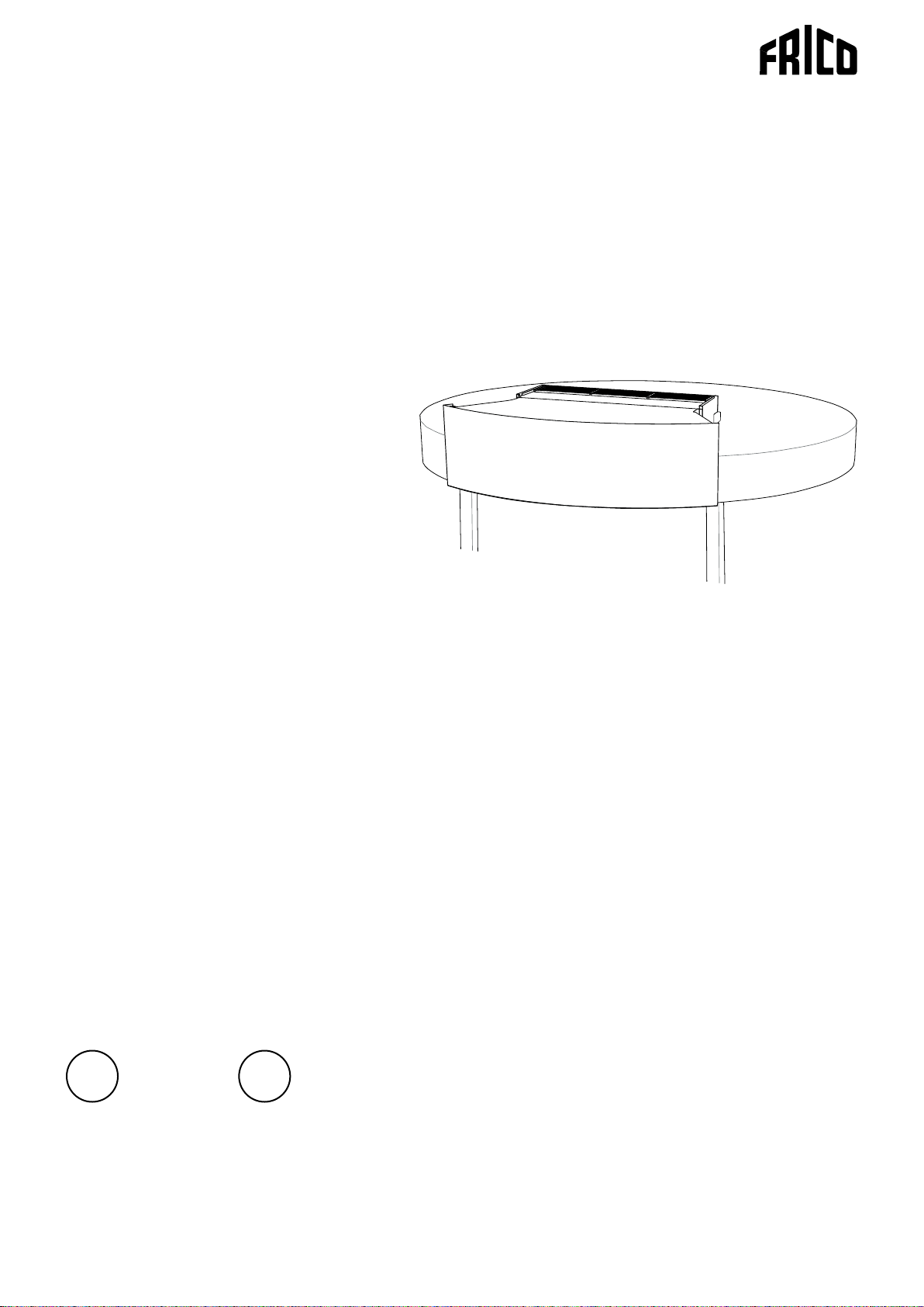
RDS is intended for revolving doors.
The air curtain is installed above the
door and the exhaust duct is adapted to the
diameter of the door, which gives a neat and
discrete solution.
Protection class: IP20
Function
Air is drawn in at the top of the unit and
blown out downwards so that it shields the
door opening and minimizes heat loss. To
achieve the optimum curtain effect the
unit must extend the full width of the door
opening.
The efficiency of the air curtain depends
on the air temperature, pressure differences
across the doorway and any wind pressure.
NOTE! Negative pressure in the building
considerably reduces the efficiency of the air
curtain. The ventilation should therefore be
balanced.
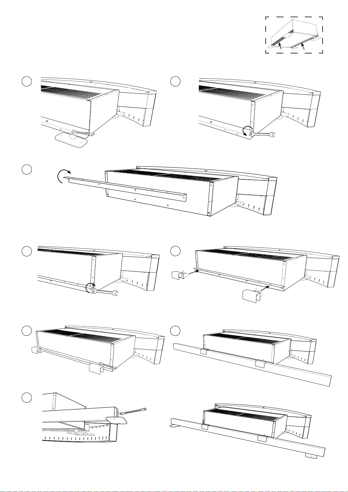
Mounting
The air curtain is installed, on steel plates
(100 x 200) that distribute the weight, on the
roof of the revolving door.
The unit could alternatively be mounted on
beams.
• Make sure that the air curtain ts on top of
the revolving door.
• The distance between the roof of the
revolving door and the inside ceiling must
not be less than 800 mm, for installation and
service to be possible.
• Ensure that the ceiling of the revolving door
can carry the weight of the air curtain and
duct. The estimated weight of the installation
is stated in the Technical specifications. If the
revolving door roof cannot take the weight,
RDS can be carried on a beam construction.
Beam mountings included.
• For installation with beams see fig. 2.
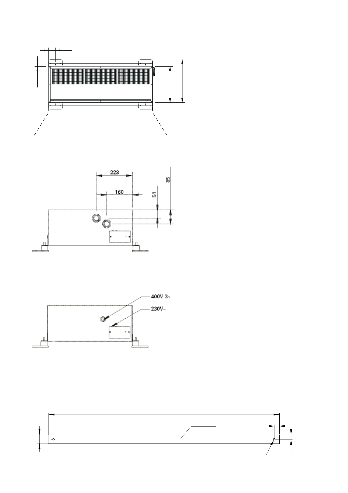
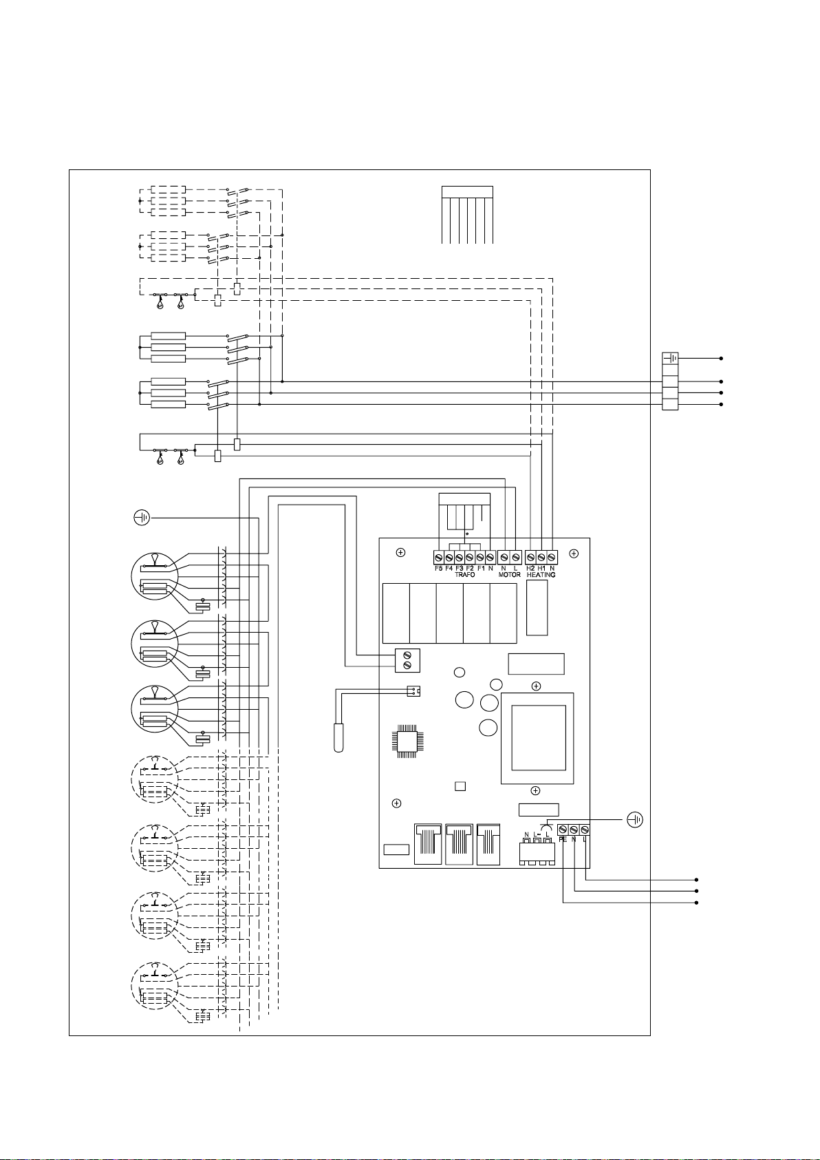
Electrical installation
The installation, which should be preceded by
an omnipolar switch with a contact separation
of at least 3 mm, should only be wired by a
competent electrician and in accordance with
the latest edition of IEE wiring regulations.
The control system is pre-installed in the air
curtain with an integrated control card.
SIRe is supplied pre-programmed with quickt connections. Modular cables are connected
to the control board.
See manual for SIRe.
Unit with water heating
Connected via the built-in control board with
2 m cord and plug.
Unit with electrical heating
The electrical connection is made on the side
of the unit.
Control (230V~) and power supply for heat
(400V3~) should be connected to a terminal
block. See g 1.
The largest cable diameter for the terminal
block is 16 mm². The cable glands used must
meet the protection class requirements. In
the distribution board it is to be indicated
that ”the air curtains can be supplied from
more than one connection”.
See wiring diagrams.
1. Service hatch is opened by removing the
screws on the top side of the unit.
2. The unit is connected via the cable gland on
the right side of the unit (seen from inside).
See wiring diagrams.
18

RDS
GB
Connecting the water coil (W)
The installation must be carried out by an
authorised installer.
The water coil has copper tubes with
aluminium fins and is suitable for connection
to a closed water heating system. The heating
coil must not be connected to a mains
pressure water system or an open water
system.
Note that the unit shall be preceded by a
regulating valve, see Frico valve kit.
The water coil is connected on the side
of the unit via DN25 (1’’), internal thread
connections.
Flexible hoses are available as an accessory,
see accessories pages.
NOTE: Care must be taken when connecting
the pipes. Use a wrench or similar to hold the
air curtain connections to prevent straining
of the pipes and subsequent water leakage
during connection to water supply pipe-work.
The connections to the heating coil must
be equipped with shut off valves (included
in Frico valve kits) to allow problem free
removal. A vent valve should be connected at a
high point in the pipe system. Air valves are not
included
Basic setting fan speed
The fan speed when the door is open is set
using the control. Note that the air flow
direction and fan speed may need fine
adjustment depending on the loading of the
door.
Filter (W)
The distance between the fins in combination
with the hole diameter of the intake grille
prevents the coil from clogging. This normally
makes a separate lter unnecessary.
Service, repairs and maintenance
For all service, repair and maintenance rst
carry out the following:
1. Disconnect the power supply.
2. Service hatch is opened by removing the
screws on the top or bottom side of the
unit.
Maintenance
Unit with water heating:
The appliance filter should be cleaned
regularly to ensure the air curtain effect and
the heat emission from the device. How often
depends on local circumstances. A clogged
lter is not a risk, but the appliance function
can fail. Vacuum the intake grille regularly
from outside when dust is visible, for example
as a part of the cleaning routine.
All units:
Since fan motors and other components are
maintenance free, no maintenance other than
cleaning is necessary. The level of cleaning
can vary depending on local conditions.
Undertake cleaning at least twice a year. Inlet
and exhaust grilles, impeller and elements
can be vacuum cleaned or wiped using a
damp cloth. Use a brush when vacuuming
to prevent damaging sensitive parts. Avoid
the use of strong alkaline or acidic cleaning
agents.
Overheating
The air curtain unit with electric heater is
equipped with an overheat protector. The
overheat protection is reset by turning
off the switch and the unit cools. If it is deployed due to overheating, reset as follows:
1. Disconnect the electricity with the fully
isolated switch.
2. Allow the electrical coil to cool.
3. Determine the cause of overheating and
rectify the fault.
4. Connect the air curtain again.
All motors are equipped with an integral thermal safety cut-out. This will operate, stopping
the air curtain should the motor temperature
rise too high. The cut-out will automatically
reset when the motor temperature has returned to within the motor’s operating limits.
Temperature control
Temperature control of SIRe maintains the
exhaust temperature. If the temperature
should exceed there is an overheating alarm.
For more information see the manual for
SIRe.
19

GB
RDS
Fan replacement
Fans are replaced through the bottom service
hatch. Alternatively the screws of the bottom
service hatch are slackened and the fans are
replaced through the top service hatch.
1. Determine which of the fans is not
functioning.
2. Disconnect the cables to the relevant fan.
3. Remove the screws securing the fan and lift
the fan out.
4. Install the new fan as above in reverse
order.
Replacing electrical coil (E)
The coil must be replaced through the top
service hatch.
1. Mark and disconnect the cables to the
electric coil.
2. Remove the mounting screws securing the
coil in the unit and lift the coil out.
3. Install the new coil in reverse order to the
above.
Replacing the water coil (W)
The coil must be replaced through the top
service hatch.
1. Shut off the water supply to the unit.
2. Disconnect the connections to the water
coil.
3. Remove the mounting screws securing the
coil in the unit and lift the coil out.
4. Install the new coil in reverse order to the
above.
For units with electrical heating, check also the
following:
• Power supply to electric heater coil; check
fuses and circuit-breaker (if any).
• That the overheat protection for the motors
has not been deployed.
For units with water coil, check also the following:
• That the water coil is air free.
• That there is enough water ow.
• That incoming water is heated enough.
If the fault cannot be rectified, please contact
a qualified service technician.
Residual current circuit breaker (E)
When the installation is protected by means
of a residual current circuit breaker, which
trips when the appliance is connected,
this may be due to moisture in the heating
element. When an appliance containing a
heater element has not been used for a long
period or stored in a damp environment,
moisture can enter the element.
This should not be seen as a fault, but is
simply rectified by connecting the appliance
to the mains supply via a socket without a
safety cut-out, so that the moisture can be
eliminated from the element. The drying
time can vary from a few hours to a few days.
As a preventive measure, the unit should
occasionally be run for a short time when it is
not being used for extended periods of time.
Draining the water coil (W)
The drain valves is on the underside of the
coil on the connector side. It can be accessed
via the service hatch.
Trouble shooting
If the fans are not working or do not blow properly,
check the following:
• That the intake grille/lter is not dirty.
• Functions and settings of the SIRe control
system , see manual for SIRe.
If there is no heat, check the following:
• Functions and settings of the SIRe control
system, see manual for SIRe.
20

Safety
• Forallinstallationsofelectricallyheated
products should a residual current circuit
breaker 300 mA for fire protection be used.
• Keeptheareasaroundtheairintake
and exhaust grilles free from possible
obstructions!
• During operation the surfaces of the unit
can be hot!
•Theunitmustnotbefullyorpartially
covered with clothing, or similar
materials, as overheating can result in a
fire risk! (E)
• Thisapplianceisnotintendedforuseby
persons (including children) with reduced
physical, sensory or mental capabilities,
or lack of experience and knowledge,
unless they have been given supervision
or instruction concerning use of the
appliance by a person responsible for
their safety. Children should be supervised
to ensure that they do not play with the
appliance.
RDS
GB
21


Main offi ce
Frico AB Tel: +46 31 336 86 00
Box 102 Fax: +46 31 26 28 25
SE-433 22 Partille mailbox@frico.se
Sweden www.frico.se
For latest updated information and information
about your local contact: www.frico.se
Art.nr: 208029, 130617, SÄ/HH
 Loading...