

Original instructions
PF Smart
SE
NL
.... 9
.... 60
EN
FI
.... 19
....71
NO
RU
.... 28
....81
DE
ES
.... 38
....92
FR
PL
.... 49
....103

PFS
SE
EN
NO
FR
DE
Introduktionssidorna består huvudsakligen av bilder. För översättning av de
engelska texter som används, se respektive språksidor.
The introduction pages consist mainly of pictures. For translation of the
English texts used, see the respective language pages.
Introduksjonssidene består hovedsakelig av bilder. For oversettelse av de
engelske tekstene, se de respektive språksidene.
Les pages de présentation contiennent principalement des images. Pour la
traduction des textes en anglais, consultez la page correspondante à la langue
souhaitée.
Die Einleitungsseiten bestehen hauptsächlich aus Bildern. Für die Übersetzung
der verwendeten Texte in englischer Sprache, siehe die entsprechenden
Sprachseiten.
NL
FI
ES
RU
PL
De inleidende pagina's bevatten hoofdzakelijk afbeeldingen. Voor een vertaling
van de gebruikte Engelse teksten, zie de pagina's van de resp. taal.
Esittelysivut koostuvat lähinnä kuvista. Suvuilla olevien enlanninkielisten
sanojen käännökset löytyvät ko. kielisivuilta.
Las páginas introductorias contienen básicamente imágenes. Consulte la
traducción de los textos en inglés que las acompañan en las páginas del
idioma correspondiente.
Страницы в начале Инструкции состоят в основном из рисунков, схем и
таблиц. Перевод встречающегося там текста приведен в разделе RU.
Początkowe strony zawierają głównie rysunki. Tłumaczenie wykorzystanych
tekstów angielskich znajduje się na odpowiednich stronach językowych.
2
PFS
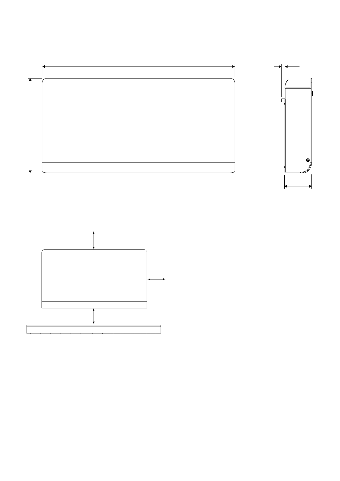
450 / 660 / 940
325
0
PFS
10
105
Fig. 1
Fig. 2: Minimum distance
min 100
min 10
min 100
3
PFS
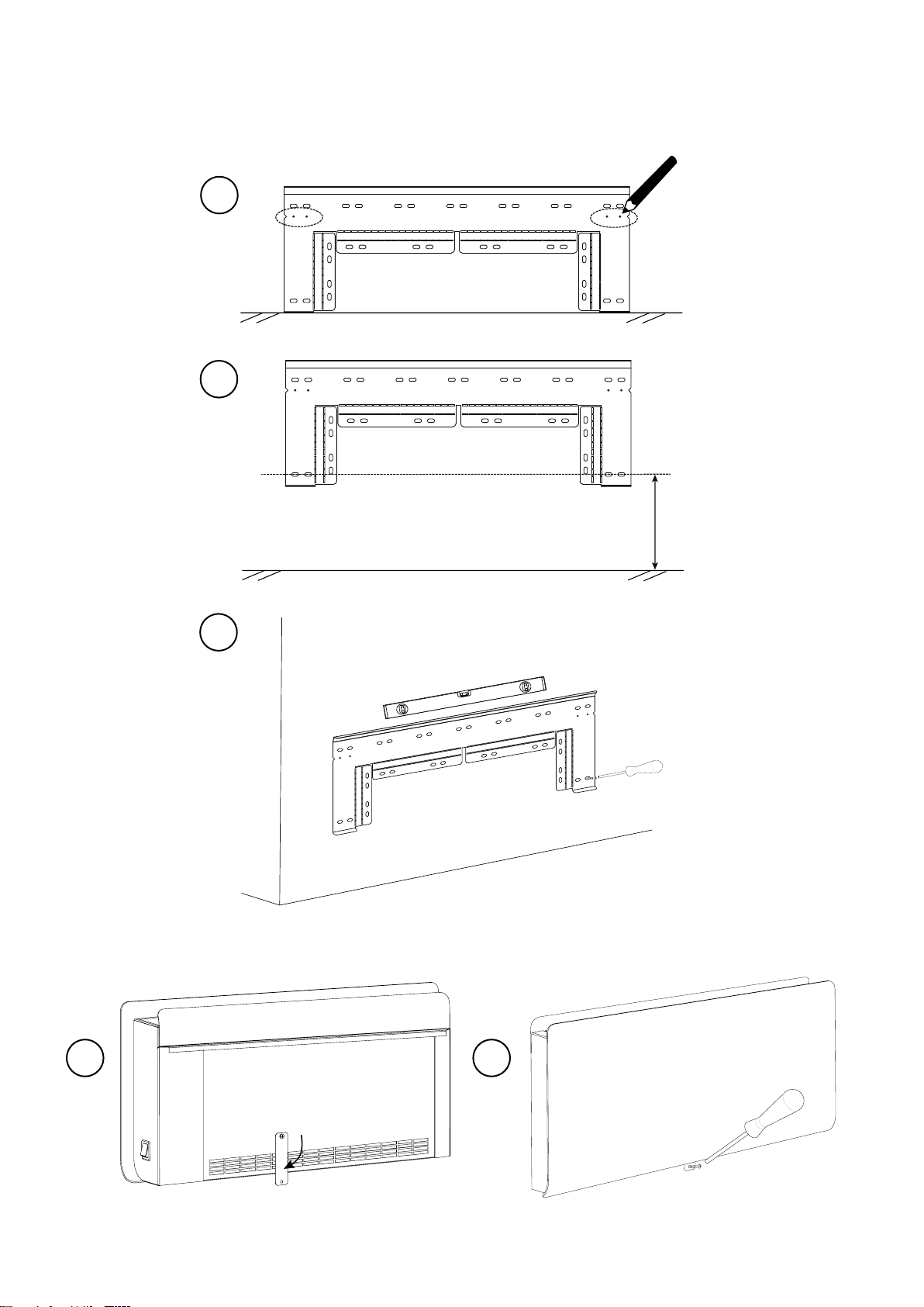
Mounting with wall bracket
Possibility to use guide holes for easy positioning
A
B
Align the wall bracket
C
Fig. 3: Mounting wall bracket
10 cm
A B
Fig. 4: Fastening with lockplate
4
PFS
11 3
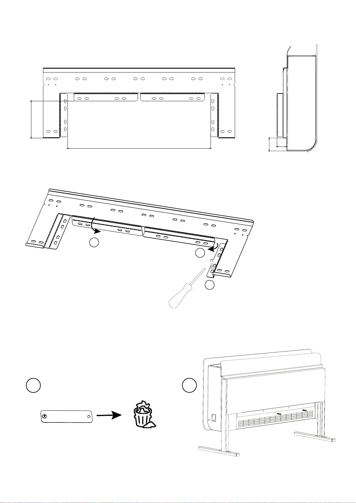
Mounting when a connection box is to be placed behind the unit
PFS4/10/17 - 214/434/712
Fig. 5: Free space to mount the connection box behind the unit
1
30
40
2
3
Fig. 6: Bending the wall bracket
Portable use
A
Fig. 7: Floor stand
B
5
PFS
A B
2
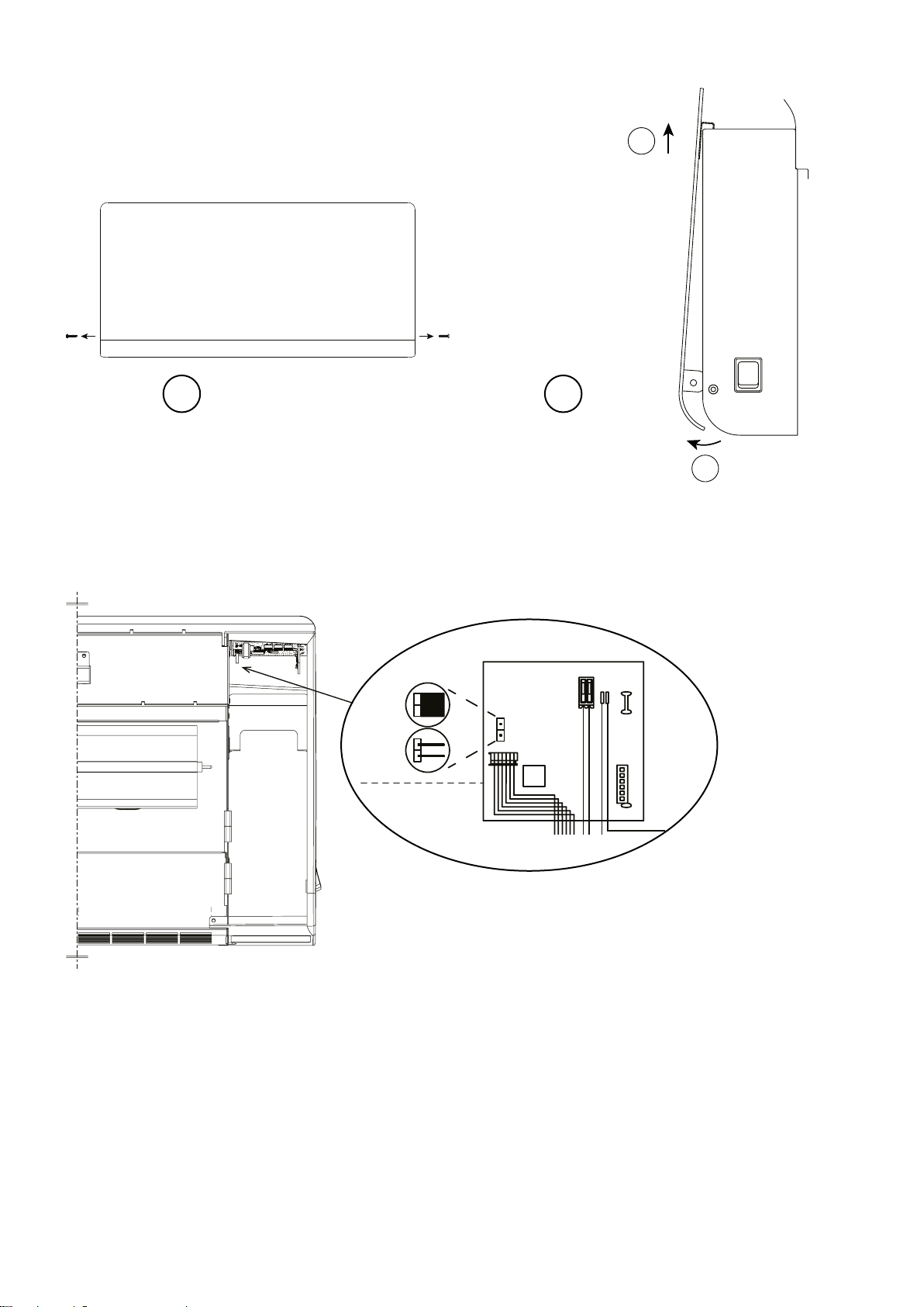
Fig. 8: Open the unit
90°C
60°C
1
DISPLAY
BOARD
12VDC
Jumper
60/90°C
RF In
Fig. 9: Changing the maximum surface temperature from 90 °C to 60 °C by removing the jumper.
Default 90 °C.
6

Accessories
PFSS4 PFSE4
PFSS10 PFSE10
PFSS17 PFSE17
PFSRF PFSE, PFSD
PFSH PFSE, PFSD
PFS
PFSS
PFSRF PFSH
3 Electrical heat 230V~ PFSE
Type Output
[W]
PFSE4
PFSE10
PFSE17
Electrical heat 400V2~ PFSD
3
Type Output
PFSD4
PFSD10
PFSD17
400 40/60 26,5/37 230V~ 1,8 1,2 450x325x105 4,1
1000 60/100 28/38,5 230V~ 4,4 1,8 660x325x105 5,8
1750 100/150 29/40,5 230V~ 7, 6 3,0 940x325x105 8,1
[W]
400 40/60 26,5/37
1000 60/100 28/38,5
1750 100/150 29/40,5
*) Conditions: Distance to the unit 2 metres. Directional factor: 2. Equivalent absorption area: 12,75 m². At
lowest/highest airflow.
Protection class: IP24.
CE compliant.
Airflow
3
[m
/h]
Airflow
3
[m
/h]
Sound
level*
[dB(A)]
Sound
level*
[dB(A)]
Voltage
[V]
Voltage
[V]
400V2~
400V2~
400V2~
Amperage
[A]
Amperage
[A]
Output
Motor (12V)
[W]
Output
Motor (12V)
[W]
LxHxD
[mm]
LxHxD
[mm]
Weight
[kg]
Weight
[kg]
1,0 1,2 450x325x105 4,1
2,5 1,8 660x325x105 5,8
4,4 3,0 940x325x105 8,1
7

PFSE / PFSD
°C
Overheat protection
OUTLET
SENSOR
PFS
90°C
60°C
DISPLAY
BOARD
12VDC
Jumper
60/90°C
POWER
BOARD
230/400V
RF In
OL
L
NON
M
PFSE/D10
PFSE/D17
M M
PFSE/D4
INLET
SENSOR
12VDC
1
0
PFSD
PFSE
8

PFS
Installation and operating instructions
EN
General Instructions
Read these instructions carefully prior to
installation and use. Keep this manual for
future reference.
The product may only be used as set out in
the assembly and operating instructions. The
guarantee is only valid should the product
be used in the manner intended and in
accordance with the instructions.
Application
With its smart functions and streamlined
design, the PF Smart fan convector is
the perfect choice for fast and efficient
heating. The PF Smart is suitable for most
environments including offices and homes.
It is ideal for installation in premises that
are used rarely, such as weekend cottages
and assembly halls where rapid heating is
desirable. In addition, the PF Smart can be
remotely controlled so that the premises is
warm by the time you arrive.
Protection class: IP24.
Approvals
• When the maximum surface temperature
is set to 60 °C, PFS is suitable for use in
preschools, afterschool recreation centres
and toilet and bathroom facilities.
• The convector is approved for installation
in wet rooms provided that no control
devices (buttons, switches, etc.) are within
reach of persons in baths or showers.
Convectors for portable use must not be
used close to pools, bathtubs or showers.
Protection class: IP24.
Mounting
Fan convector PFS is mounted on the wall
with the included wall bracket. The convector
must not be placed immediately under a
fixed socket. For minimum dimensions with
permanent installation, see fig. 2. PFSE can
also be used as a portable unit, floor stand is
available as an accessory.
Mounting with wall bracket
1. Mount the wall bracket stable on the wall
with screws in the oval holes (at least 2x).
It is important that the wall bracket is
aligned to a straight horizontal position.
Guide holes on the wall bracket can be used
to mark out where the bracket should be
positioned to end up 10 cm above the floor.
Fig. 3.
2. Hang the fan convector on the wall bracket.
3. Rotate the lock plate (Fig. 4) and fasten
with a screw in the wall, so that the fan
convector is mounted securely.
Mounting when a connection box is to be used
To enable the installation of a surface
mounted connection box behind the fan
convector, the wall bracket is bent in order to
place the unit further from the wall. See Fig. 5
and 6.
1. Bend the wall bracket acc. to Fig 6. The
holes in the bent-down part are used to
fasten the wall bracket to the wall.
2. Follow steps 1-3 in section "Mounting with
wall bracket".
Portable use
PFSE can also be used as a portable unit.
Floor stand PFSS is available as an accessory.
Fig. 7.
1. Mount the floor stand with the included
screws.
2. Hang the fan convector on the floor stand.
The lock plate is not used and should be
removed.
3. Fasten the stand to the unit with screws
included, in intended holes, PFSE4 1x,
PFSE10/17 2x.
Connection
PFSE is equipped with a 1.2 metre long
cord with plug for connection to an earthed
power socket (230V~). PFSD is intended for
permanent installation and is connected via
cable without plug.
The installation, which should be
preceded by an isolator switch with a contact
separation of at least 3 mm, should only
be wired by a competent electrician and in
accordance with the latest edition of IEE
wiring regulations.
Fan convector PFS is switched on with the
switch placed low on the right plastic end.
See wiring diagrams.
19

EN
PFS
Switching surface temperature 60 / 90 °C
On delivery, max. surface temperature is
set to 90 °C. To select the lower surface
temperature - max 60 °C, remove the jumper
on the circuit board placed below the display
inside the convector.
1. Disconnect the power supply.
2. The front is opened by removing the screws
on the plastic ends (2x), pull the front at
the bottom and then lift it up. (Fig. 8)
3. Remove the jumper. Fig. 9.
4. Reinstall the front.
A surface temperature of 60 °C can at some
conditions result in a power reduction, to
keep the temperature low.
Start-up (E)
When the unit is used for the first time or
after a long period of non-use, smoke or an
odour may result from dust or dirt which has
collected on the element. This is completely
normal and disappears after a short time.
Service, repairs and maintenance
For all service, repair and maintenance first
carry out the following:
1. Disconnect the power supply.
2. The front is opened by removing the screws
on the plastic ends (2x), pull the front at
the bottom and then lift it up. (Fig. 8)
3. Reinstall the front.
Maintenance
In all electrical heating appliances, small
clicks can occur due to movement when the
material expands and contracts with changes
in temperature.
Since fan motors and other components are
maintenance free, no maintenance other than
cleaning is necessary. The level of cleaning
can vary depending on local conditions.
Undertake cleaning at least twice a year. Inlet
and exhaust grilles, fans and elements can be
vacuum cleaned or wiped using a damp cloth.
Use a brush when vacuuming to prevent
damaging sensitive parts. Avoid the use of
strong alkaline or acidic cleaning agents.
Overheat protection
The fan convector is equipped with overheat
protection. The overheat protection resets by
turning off the unit during 10 minutes.
Replacing the fan motor
1. Disconnect the power supply.
2. The front is opened by removing the screws
on the plastic ends (2x), pull the front at
the bottom and then lift it up. (Fig. 8)
3. Disconnect the cables to the motor.
4. Remove the screws securing the motor and
lift it out.
5. Install the new motor as above in reverse
order.
6. Reinstall the front.
Packaging
Packaging materials are chosen with
consideration to the environment and are
therefore recyclable.
Handling of product at end of working life
This product may contain substances
necessary for the functionality of the product
but potentially dangerous for the environment.
The product should not be disposed of mixed
with general household waste but delivered to
a designated collection point for environmental
recycling. Please contact the local authority
for further details of your nearest designated
collection point.
Safety
• For all installations of electrically heated
products a residual current circuit breaker
300 mA for fire protection should be used.
• Keep the areas around the air intake
and exhaust grilles free from possible
obstructions!
• The unit must not be fully or partially
covered as overheating can result in a fire
risk!
• This appliance can be used by children
aged from 8 years and above and persons
with reduced physical, sensory or
mental capabilities or lack of experience
and knowledge if they have been given
supervision or instruction concerning
use of the appliance in a safe way and
understand the hazards involved. Children
shall not play with the appliance. Cleaning
and user maintenance shall not be made by
children without supervision.
20

PFS
EN
• Children of less than 3 years should be
kept away unless continuously supervised.
• Children aged from 3 years and less than 8
years shall only switch on/off the appliance
provided that it has been placed or
installed in its intended normal operating
position and they have been given
supervision or instruction concerning
use of the appliance in a safe way and
understand the hazards involved.
Control
• This product is considered a local space
heater according to Ecodesign Regulation
(EU) 2015/1188 and is equipped with smart
control which among others includes :
• Electronic room temperature control plus
week timer
• Room temperature control with open
window detection
• Adaptive start control
• Children aged from 3 years and less
than 8 years shall not plug in, regulate
and clean the appliance or perform user
maintenance.
CAUTION — Some parts of this product can
become very hot and cause burns. Particular
attention has to be given where children and
vulnerable people are present.
PF Smart App
PF Smart can also be remotely controlled
via an app (iOS, Android) or web browser.
Requires an RF module per fan convector,
hub and wireless Internet connection. See
accessories in the introduction pages and
separate manual.
The fan convector has a digital display on
which all settings are made and can also be
remotely controlled via an app (iOS, Android)
or web browser.
Start up
Home screen and keypad
7
A
6
8
°C
9
1
4
OK
3
Keypad
1 Increase / up
2 Decrease / down
3 User menu / browse / proceed
4 Return
5 Confirm / select
Display
6 Desired room temperature (set point)
7 Fan mode Auto active
8 Temperature mode Comfort active
9 Heat on
When the screen is inactive, it can be
activated by pressing any key.
2
5
21

EN
PFS
PF Smart is supplied with default settings.
The temperature is easily changed by pressing
+ or -. PF Smart can also be adapted to
individual requirements, see the following
pages.
At the first start-up or after a longer power
failure, the time needs to be set. If a week
program is not to be used and the time does
not need to be set, this can be overridden by
pressing the OK button repeatedly until the
home screen appears.
Default settings
Set point
Fan mode
Temperature mode
Quick commands
Press and hold Quick command
+
+
21 °C
Auto
Comfort
Display lock on/off
Show time and weekday
Current room temperature
(actual value)
Display symbols
Fan on
Fan off. Flashes
OFF
when cooling.
A
Fan Auto mode
Active fan steps
Symbol flashing
Sending/reception
RF
Symbol flashing
Open window mode on
Display lock on
Comfort mode
Reduced (night mode)
Frost protection
Symbol flashing
Timer on
OFF
A
P
°C
Week program on
P
Weekday:
1 = Mon to 7 = Sun
Heat on
Surface temperature 60 °C
Surface temperature 90 °C
22
Timeline for the current week
program. Black timing marks =
comfort mode

Fan mode
The fan speed can be set to suit any
requirements. Modes: Auto/Low/High/Off.
User menu
Select
A
OK
P
Confirm
Set the desired fan mode.
PFS
Fan mode
Auto
OFF
EN
Functions
The fan runs at low speed except:
- when the room temperature is
more than 2 °C below the set point,
then the fan speed increases to
high speed for a shorter heating
time.
- if it is too hot in the the unit
The fan is off.
When Off is selected, the fan first
runs during a cooling period until
the right temperature is reached before it stops. To prevent excessive
internal temperature, the internal
sensor may reduce the power.
A
Auto OFF
OK
Confirm
OFF
High Low
Temperature mode
It is possible to choose between three modes comfort, reduced mode (night mode) or frost
protection. Settings for Comfort mode and
Reduced mode are also applied in the week
program when used.
Low
High
Default settings
Temperature mode Fan mode Set point
Comfort mode
Reduced (night mode)
Frost protection
Low speed.
To prevent excessive internal temperature, the internal sensor may
reduce the power.
High speed
21 °C
18 °C
10 °C
High (locked)
OK
OK
User menu
Select mode in the user menu:
Comfort mode
Reduced (night mode)
Frost protection
Confirm
Set the desired room temperature.
Confirm
See section Fan modes to set the desired
fan mode. For temperature mode Frost
protection, the fan mode is locked to High (for
maximum heat distribution).
23

EN
PFS
Timer
The set temperature can be changed for a
limited time with the timer (1 hour to 45
days). The fan runs on the set value.
User menu
Select
A
OK
A
P
Confirm
Set the desired time.
P
Week program
PFS has nine preset week programs (P1 to P9)
and the possibility to add four (U1-U4).
The function ITCS (default) makes the
control learn when it needs to start in order
to reach a certain desired temperature at a
specific time in the environment it is used. It
can be disabled, see Settings.
Preset programs
Comfort mode
Program
P1 05:30 - 08
P2 06:30 - 10
Description
Residence
Residence,
late
*
Mon-Fri:
Sat-Sun:
Mon-Fri:
17 - 22
07 - 23
19 - 23:30
1h - 45d
OK
OK
Confirm
Set the desired room temperature.
A
P
°C
Confirm
While the timer is running, its symbol
flashes and the display alternately shows the
remaining time and the set temperature.
When time is up the unit returns to previous
settings.
Sat-Sun:
P3 06 - 09
P4 06 - 22
P5 17 - 23
P6 06 - 18
P7 09 - 21
P8 09 - 22
P9 09 - 18
*) Other times: Reduced (night mode)
Residence,
short
Residence,
day only
Weekend
Office
Office, late
Shop, late
Shop
Mon-Fri:
Sat-Sun:
Mon-Sun:
Fri:
Sat-Sun:
Mon-Fri:
Mon-Fri:
Mon-Fri:
Sat-Sun:
Mon-Fri:
Sat-Sun:
07:30 - 23:30
16 - 23
07 - 23
07 - 23
09 - 20
09 - 14
Read more on the following pages.
24

PFS
EN
Setting week programs
User menu
Select
A
P1 or the recently used program is shown.
OK
Selecting a preset program P1 - P9
OK
Confirm
Select P1-P9.
Switch between days of the week with
the arrow to view times for the selected
program. 1 = Mon to 7 = Sun. The times
when Comfort mode is active can be seen
in the lower part of the display of the
selected weekday.
Confirm with ok to start the program.
P
P
Select the start time for the selected mode
(Reduced/Comfort).
P
OK
OK
OK
These steps can be repeated until a full program is
set. When the program is finished, proceed to the
next day.
Confirm
Select between Reduced mode or Comfort
mode for following time.
Confirm
Select the start time for the selected mode
(Reduced/Comfort).
P
Confirm
Following days, Tue - Sun
Setting your own week program U1-U4
Select U1-U4.
OK
Press and hold OK for 2 s. to confirm.
Monday
Select if you want to begin the setting for
Reduced mode or Comfort mode.
P P
Comfort modeReduced (night mode)
Proceed to the next day.
Select copy (COPY) to copy the previous
day's settings or no (no).
°C °C
No to copyYes to copy
OK
If no (no) is selected, settings are made in the same
way as for Monday 1.
When all 7 days are completed, save (SAVE) can be
selected.
Confirm
Select yes to save (YE) or no (no).
OK
Confirm
OK
Confirm with ok to start the program.
25

EN
PFS
Settings
A
OK
OK
options
Time (01)
User menu
Select
P
Confirm
Browse the menu options.
Confirm
Functions Menu
For week program. Time and date.
Power failure
Note! A power loss longer than 12 hours may
require an adjustment of time and date. The
week program is affected if the clock is not
correctly set.
Default
settings
Must be set
if the week
program is
to be used.
Description
Set the following:
- hour (24 h)
- minute
- weekday: mon=1, sun=7
- day/month
- year
Increase/decrease with +/-.
Confirm every step with OK.
dst (02)
Frt (03)
In t (04) ItcS (05)
rF (06) -
oPn (07)
clr (08) -
uEe (09) -
For week program. Daylight saving/summer time and winter time.
For week program. No fan (fan off) in
reduced mode.
Read internal temperature.
For week program. The control learns
when it needs to start in order to reach a
certain desired temperature at a specific
time in the environment it is used.
For PF Smart App. Linking the RF module
to the control.
Open window mode to save energy. If the
temperature drops more than 3 °C in one
minute, the control enters frost protection
mode for 15 minutes (see Temperature
mode). Unless the temperature drops
further, the control returns to previous settings after 15 minutes.
Factory reset. Resets values to factory settings.
Read version number.
On (on)
OFF (off)
On (on)
On (on)
Switch between on (on) and off
(OFF) with +/-.
Confirm with OK.
Switch between on (on) and off
(OFF) with +/-.
Confirm with OK.
Press OK to return to the menu.
Switch between on (on) and off
(OFF) with +/-.
Confirm with OK.
See separate manual for PF Smart
App.
Switch between on (on) and off
(OFF) with +/-.
Confirm with OK.
Switch between no (no) and yes
(YES) with +/-.
To factory reset, choose yes by
pressing OK about 4 seconds
(countdown).
Press OK to return to the menu.
26

Troubleshooting
PFS
EN
ActionSymptom Cause
The fan symbol is
flashing. No heat
and the fan runs at
maximum speed.
The text "Heat OFF"
appears. No heat.
The text "Sens Out"
flashes in the display
and there is no heat.
The internal temperature has exceeded
the upper limit, even though the heat
is off. The fans automatically run at the
highest speed and the heat is blocked
until the internal temperature is below
the limit, and then return to the previous
settings.
The control considers that no heat is
emitted from the heating element. (The
temperature difference between the
room sensors and internal sensors is
less than 5 °C after 90 sec.)
The upper sensor is defective or is detached from its fastening.
• Check that the air flow is not
blocked at the intake grille or
outlet grille.
• Clean the inside of the unit.
• Check that the internal sensor
(at the outlet grille) are placed
correctly.
• Check that the air flow is not
blocked at the intake grille or
outlet grille.
• Disconnect the power for at least
10 minutes in order to reset the
overheat protection.
• Reconnect power and cancel the
alarm by pressing the OK button
for 3 seconds.
Contact Frico for support.
The text "Sens In"
flashes in the display
and there is no heat.
The fan convector emits
heat, but it becomes
progressively more
difficult to achieve
the desired room
temperature, even
though the settings are
unchanged.
All the fans are inactive.
The lower sensor is defective or is detached from its fastening.
The internal temperature reaches its limit
value faster, which limits the heat emission.
The fan speed is set to OFF.
The function with fans off at reduced
mode (FRT) is active.
The quick plug for the first motor is detached.
Contact Frico for support.
• Check that the air flow is not
blocked at the intake grille or
outlet grille.
• Clean the inside of the unit.
• Check that all motors operate
correctly.
Switch fan mode to Auto.
Put FRT function to OFF in Settings.
Check the fan motor connections.
If the problems continue, please contact Frico for support.
27

Main offi ce
Frico AB Tel: +46 31 336 86 00
Industrivägen 41
SE-433 61 Sävedalen mailbox@frico.se
Sweden www.frico.net
For latest updated information and information
about your local contact: www.frico.net.
Art.no 211237, 2019-09-02,HH/CH
 Loading...