

Original instructions
Pamir 2500
EN
NL
FI
.... 13
.... 38
....65
SE
ES
DK
.... 17
....43
.... 70
NO
IT
.... 22
....48
FR
PL
.... 27
.... 54
DE
RU
....32
.... 59

Pamir 2500
EN
SE
NO
FR
DE
The introduction pages consist mainly of pictures. For translation of the English
texts used, see the respective language pages.
Introduktionssidorna består huvudsakligen av bilder. För översättning av de
engelska texter som används, se respektive språksidor.
Introduksjonssidene består hovedsakelig av bilder. For oversettelse av de
engelske tekstene, se de respektive språksidene.
Les pages de présentation contiennent principalement des images. Pour la
traduction des textes en anglais, consultez la page correspondante à la langue
souhaitée.
Die Einleitungsseiten bestehen hauptsächlich aus Bildern. Für die Übersetzung
der verwendeten Texte in englischer Sprache, siehe die entsprechenden
Sprachseiten.
ES
NL
IT
PL
RU
Las páginas introductorias contienen básicamente imágenes. Consulte la
traducción de los textos en inglés que las acompañan en las páginas del idioma
correspondiente.
De inleidende pagina's bevatten hoofdzakelijk afbeeldingen. Voor een vertaling
van de gebruikte Engelse teksten, zie de pagina's van de resp. taal.
Le pagine introduttive contengono prevalentemente immagini. Per le
traduzioni dei testi scritti in inglese, vedere le pagine nelle diverse lingue.
Początkowe strony zawierają głównie rysunki. Tłumaczenie wykorzystanych
tekstów angielskich znajduje się na odpowiednich stronach językowych.
Страницы в начале Инструкции состоят в основном из рисунков, схем и
таблиц. Перевод встречающегося там текста приведен в разделе RU.
2
FI
DK
Esittelysivut koostuvat lähinnä kuvista. Suvuilla olevien enlanninkielisten
sanojen käännökset löytyvät ko. kielisivuilta.
Introduktionssiderne består hovedsageligt af billeder. For oversættelse af de
engelske tekster, se siderne for de respektive sprog.
PAF2500
Cu ø1
345
min 500
157
90,5
10
20
40
210
165
1026 / 1536 / 2026
1050 / 1560 / 2050
Cu ø15
53
345
min 500
min 500
min 500
157
157
157
90,5
10
20
40
22
210
165
184
1026 / 1536 / 2026
1050 / 1560 / 2050
Cu ø15
53
71 40
Cu ø15
Pamir 2500
1026 / 1536 / 2026
20
210
1050 / 1560 / 2050
90,5
165
40
5
53
2 m
PAF2500A PAF2500W
1
2
157
min 500
min 500
157
min 500
10
345
157
3
Fig.1
184
22
Cu ø15
PAF2500E
71 40
min 500
min 500
157157
3
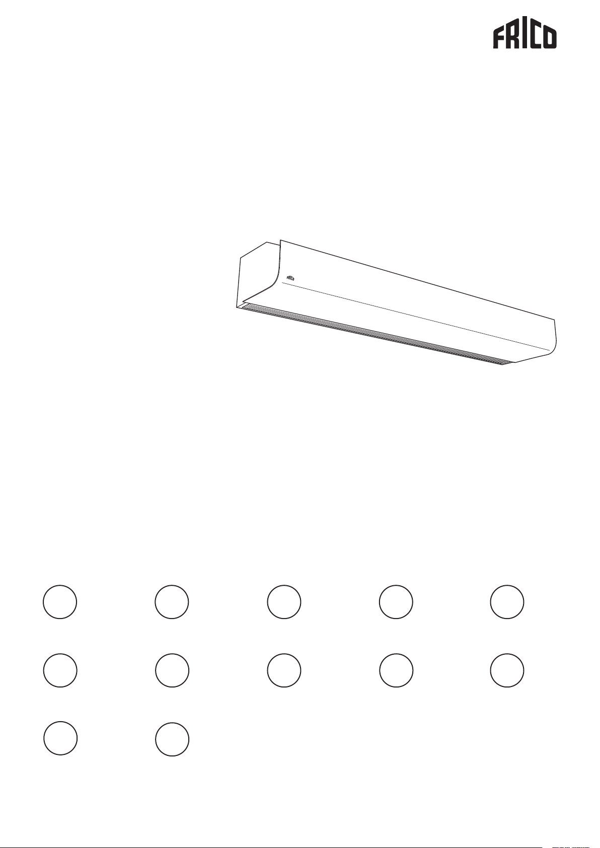
Gland
ø17, 5ø17,5
ø1
Pamir 2500
Knock-out
7, 5
Gland
Gland
ø32,5
ø25,5
ø20,5
Knock-out
Knock-out
Gland
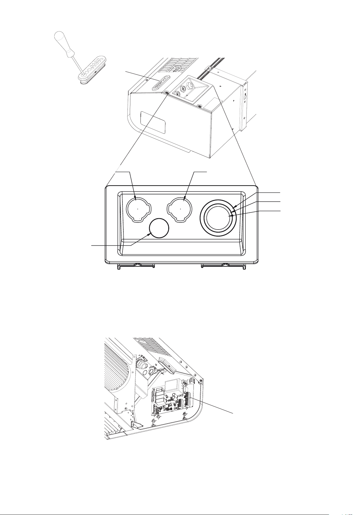
Fig. 2: PC board FC is integrated within the air curtain at delivery.
4
PC board FC Frico control
Pamir 2500
min 60
A B
TX20
C
Fig.3: Open the unit.
Fig.4: Minimum distance.
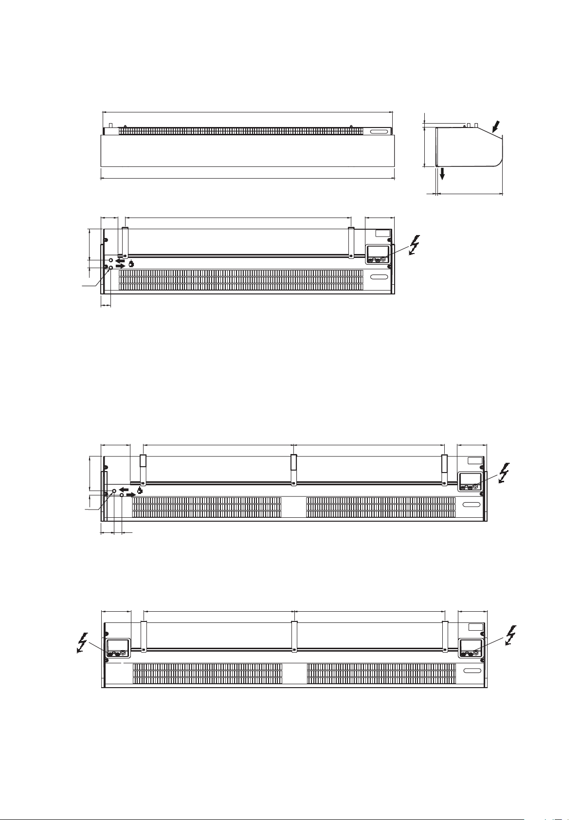
5
210
Pamir 2500
Mounting with wall brackets
A B
min 500 mm
ø8 (3x)
203575
ø5
ø10
162
C D
33
PAF2510 2 pcs
PAF2515 2 pcs
Fig. 6: Mounting with wall brackets
PAF2520 3 pcs
6

Accessories
Pamir 2500
PA2PF
PA34TR
Item
number
18056 PA34TR15* PAF2510, PAF2515 4 pcs 1 m
18057 PA34TR20* PAF2520 6 pcs 1 m
19568 PA2P15* PAF2510, PAF2515 2 pcs 1m
19569 PA2P20* PAF2520 3 pcs 1 m
19415 PA2PF15* PAF2510, PAF2515 4 pcs
19417 PA2PF20* PAF2520 6 pcs
14875 PA2EF10 PAF2510W
14876 PA2EF15 PAF2515W
14877 PA2EF20 PAF2520W
27279 PAWAK PAF2500W
77179 FHDN15 PAF2500W
Type Consists of Length
PA2P
PAWAK
FHDN15
PA2EF
*) See separate manual.
Valve systems
Item
number
238293 VPFC15LF DN15 0,012-0,068
238294 VPFC15NF DN15 0,024-0,13
238295 VPFC20 DN20 0,058-0,32
238296 VPFC25 DN25 0,10-0,60
238297 VPFC32 DN32 0,22-1,03
See separate manual.
Type Connection Flow range
[l/s]
VPFC
VKF
SDM
7

Pamir 2500
Control systems
The air curtain must be supplemented with a control system.
FCDA - FC Direct FCSA - FC Smart
FCBC05FCDCFCCF
FCBC10FCDCFCCF
FCLAP
FCPA - FC Pro FCBA - FC Building
FCBC10FCDCFCCF
Item
number
74684 FCDA FC Direct 89x89x26 mm (FCCF)
74685 FCSA FC Smart 89x89x26 mm (FCCF)
74686 FCPA FC Pro 89x89x26 mm (FCCF)
74687 FCBA FC Building 89x89x26 mm (FCCF)
Type Name Dimensions
FCLAP
FCTXRF
Accessories
FCBC10FCDCFCCF
FCBAP
FCRTX
FCSC10
Item
number
74694 FCRTX 39x39x23 mm
74695 FCOTX 39x39x23 mm
74699 FCLAP 89x89x26 mm
74702 FCWTA for PAF2500W
17495 FCDC
74718 FCBC05 5 m
74719 FCBC10 10 m
74720 FCBC25 25 m
74721 FCSC10 10 m
74722 FCSC25 25 m
74703 FCTXRF for FC Smart, FC Pro 89x89x26 mm
Type Dimensions
FCOTX
FCSC10
See separate manual for FC.
FCLAP
FCBC10
FCBC05/10/25
FCSC10/25
FCDCFCWTA
FCTXRF
8

PAF2510E / PAF2515E / PAF2520E
Pamir 2500
246873
230V IN
L
PE N
PE
Traf o
24VWTA
Actuator
HI
LO
E1 E2 - +
BUS 1 BUS 2
+12V
GND
+12V
GND
HI
LO
2510E/2515E/2520E
OFF
Termination
ON
GND
GND
A1 A2
B1 B2 D1 D2
FCBASEPCB T3
Outle t sensor
Inlet sensor
I1 I2 O1O2
GND
0-10V
PWM
N F2 F3F1H1 H2N
Heating
400V 3N~
L1L2L3 LP E N
Motor
C1
C2
Motor
Alarm
Sensor
C3
Run
Lo
C2
C
°
cut-out
Over heat
C2 = high power
400V3~
L1
L3 L2 PE
C3
C1 = low power
C
°
cut-out
Over heat
C4
Only 2 m version
C2 = high power
C1 = low power
Wiring diagrams for control system in the FC manual.
C1
Mid
Black
Brown
Blue
Black
Brown
Blue
Type C1 Mid
[mF]
°
C
C3
Run
Lo
C2
C1
Mid
°
C
C2 Low
[mF]
PAF2510E 10 6 4
PAF2515E 12 8 4
PAF2520E 10 6 4
~
M
Right motor
~
M
Left mo tor
C3 Run
[mF]
9

Pamir 2500
PAF2510A / PAF2515A / PAF2520A
PAF2510W / PAF2515W / PAF2520W
230V IN
L
PE N
PE
Traf o
2 4 VW T A
Actuator
LO
E1 E2 - +
BUS 1 BUS 2
+12V
GND
+12V
GND
HI
LO
HI
OFF
Termination
ON
GND
GND
A1 A2
B1B2 D1 D2
2510A/2515A/2520A
2510W/2515W/2520W
246872
FCBASEPCB T3
Inlet sensor
Outlet sensor
Water models only
I1 I2 O1O2
GND
0-10V
PWM
Heating
N F2 F3F1H1 H2N
Motor
Motor
Alarm
Sensor
C3
Run
Lo
C2
Only 2 m version
Wiring diagrams for control system in the FC manual.
C1
Mid
Black
Brown
Blue
°
C
C3
C2
C1
Black
Brown
Blue
°
C
Type C1 Mid
~
M
Righ t motor
Run
Lo
Mid
~
M
Left motor
C2 Low
[mF]
[mF]
PAF2510A/W 10 6 4
PAF2515A/W 12 8 4
PAF2520A/W 10 6 4
C3 Run
[mF]
10

Pamir 2500
PAF2510E05YD / PAF2515E08YD / PAF2520E10YD
246874
230V IN
PE N
L
PE
Trafo
24VWTA
Actuator
BUS 1 BUS 2
+12V
GND
+12V
GND
HI
LO
HI
LO
E1 E2 - +
OFF
Termin ation
ON
GND
GND
A1 A2
B1B2 D1D2
2510EYD/2515EYD/2520EYD
FCBASEPCB T3
Outle t sensor
230V 3~400V 3N~
L1
L3 L2 N LP E
NP E L
L1L3 L2
N F2 F3F1H1 H2N
Heating Motor
I1 I2 O1 O2
GND
0-10V
PWM
Alarm
Motor
Sensor
Inl et sensor
C1
C2
C3
Run
C
L1 PE
230V3~
400V3~
L2L3
230V 3~
L2
L3 L1 PE
c1
a2
c2
b2
c2
a1
b1
b2
400V 3~
a1
c1b1a2
C3
C4
a1
c1
a2
c2
a1
c1
a2
c2
b2
b1
230V 3~
400V 3~
b1
b2
°
Over heat
C
°
Over heat
Onl y 2 m version
Wiring diagrams for control system in the FC manual.
Lo
C2
cut-out
Black
Brow n
Blue
cut-out
Black
Brow n
Blue
Type C1 Mid
[mF]
PAF2510E05YD
10 6 4
C1
Mid
°
C
C3
Run
Lo
C2
C1
Mid
°
C
C2 Low
[mF]
~
M
Right motor
~
M
Left motor
C3 Run
[mF]
PAF2515E08YD 12 8 4
PAF2520E10YD 10 6 4
11

Pamir 2500
Technical specications Pamir 2500
Ambient, no heat - PAF2500 A (IP21)
1
Item
number
246826 PAF2510A 0 900/1300 70 43/53 115 0,5 16
246830 PAF2515A 0 1250/2100 71 44/54 155 0,7 24
246834 PAF2520A 0 1800/2600 72 44/55 230 1,0 32
Type Output
[kW]
Airow*1
[m3/h]
Sound
power*2
[dB(A)]
Sound
pressure*3
[dB(A)]
Motor
[W]
Voltage motor: 230V~
Amperage
motor
[A]
Weight
[kg]
3 Electrical heat - PAF2500 E (IP20)
Item
number
246823 PAF2510E05 1,7/3,3/5,0 900/1450 17/11 68 42/51 115 0,5 400V3~/7,2 19
246824 PAF2510E08 3,0/5,0/8,0 900/1450 27/17 68 42/51 115 0,5 400V3~/11,5 20
246827 PAF2515E08 2,7/5,3/8,0 1400/2200 18/11 69 40/52 115 0,7 400V3~/11,5 30
246828 PAF2515E12 4,0/8,0/12 1400/2200 26/17 69 40/52 155 0,7 400V3~/17,3 32
246831 PAF2520E10 3,4/6,6/10 1800/2900 17/11 70 43/53 230 1,0 400V3~/14,4 36
246832 PAF2520E16 6,0/10/16 1800/2900 27/17 70 43/53 230 1,0 400V3~/23,1 40
Type Output
steps
[kW]
Airow*1
[m3/h]
∆t
[°C]
*4
Sound
power*2
[dB(A)]
Sound
pressure*3
[dB(A)]
Motor
[W]
Amperage
motor
[A]
Voltage [V]
Amperage
[A] (heat)
Weight
[kg]
2 Water heat - PAF2500 W (IP21)
Item
number
246825 PAF2510W 4,7 900/1300 12/11 0,7 69 42/53 105 0,45 18
246829 PAF2515W 9,2 1250/2100 16/13 1,1 70 41/54 140 0,6 26
246833 PAF2520W 11 1800/2600 15/13 1,4 71 43/55 210 0,9 35
Type Output*5
[kW]
Airow*1
[m3/h]
∆t
[°C]
*4,5
Water
volume
[l]
Sound
power*2
[dB(A)]
Sound
pressure*3
[dB(A)]
Motor
[W]
Amperage
motor
[A]
Weight
[kg]
3 Electrical heat - PAF2500 E 230V3~ (IP20)
*4
Item
number
246835 PAF2510E05YD 1,7/3,3/5,0 900/1450 17/11 68 42/51 0,5 230V3~/400V3~ 12,6/7,2 19
246836 PAF2515E08YD 2,7/5,3/8,0 1400/2200 18/11 69 40/52 0,7 230V3~/400V3~ 20,1/11,5 20
246837 PAF2520E10YD 3,4/6,6/10 1800/2900 17/11 70 43/53 1,0 230V3~/400V3~ 25,1/14,4 40
*1) Lowest/highest airow of totally 3 fan steps.
2
*
) Sound power (LWA) measurements according to ISO 27327-2: 2014, Installation type E.
3
*
) Sound pressure (LpA). Conditions: Distance to the unit 5 metres. Directional factor: 2. Equivalent absorption area:
200 m². At lowest/highest airow.
4
*
) ∆t = temperature rise of passing air at maximum heat output and lowest/highest airow.
5
*
) Applicable at water temperature 60/40 °C, air temperature, in +18 °C. See www.frico.net for additional calculations.
Type Output
steps
[kW]
Airow*1
[m3/h]
∆t
[°C]
Sound
power*2
[dB(A)]
Sound
pressure*3
[dB(A)]
Amp.
motor
[A]
Voltage
heat
[V]
Amp.
heat
[A]
Weight
[kg]
12

Pamir 2500
Installation and operating instructions
EN
General Instructions
Read these instructions carefully prior to
installation and use. Keep this manual for
future reference.
The product may only be used as set out in
the assembly and operating instructions. The
guarantee is only valid should the product be used
in the manner intended and in accordance with
the instructions.
Application
Pamir 2500 has a recommended installation
height of 2,5 m. The air curtain is available
without heat, with electrical heating and with
water heating. Protection class for units with
electrical heating: IP20.
Protection class for units without heating and
units with water heating: IP21.
Operation
Air is drawn in at the top of the unit and blown
downwards shielding the door opening and
minimizing heat loss. To achieve the optimum
curtain effect the unit must extend the full
width of the door opening.
The grille for directing the outlet air is
adjustable and is normally angled outwards to
achieve the best protection against incoming
air.
The eciency of the air curtain depends on
the air temperature, the pressure differencial
across the doorway and any wind load.
NOTE! Negative pressure in the building
considerably reduces the eciency of the air
curtain. The ventilation should therefore be
balanced.
Mounting
The air curtain is installed horizontally with
the outlet air grille facing downwards as close
to the door as possible. The product must be
mounted in such a way to allow future service
and maintenance. Minimum distance from
outlet to oor for electrically heated units is
1800 mm. For other minimum distances, see
g. 4.
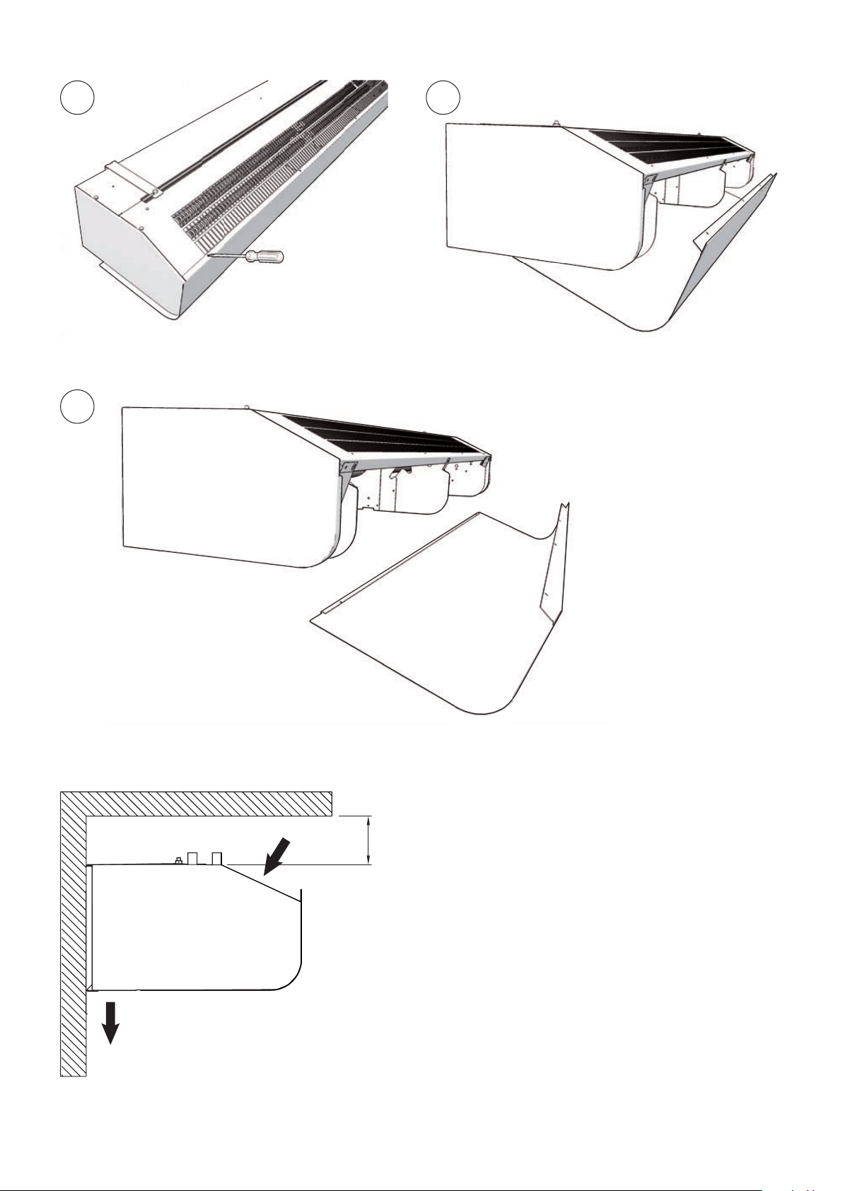
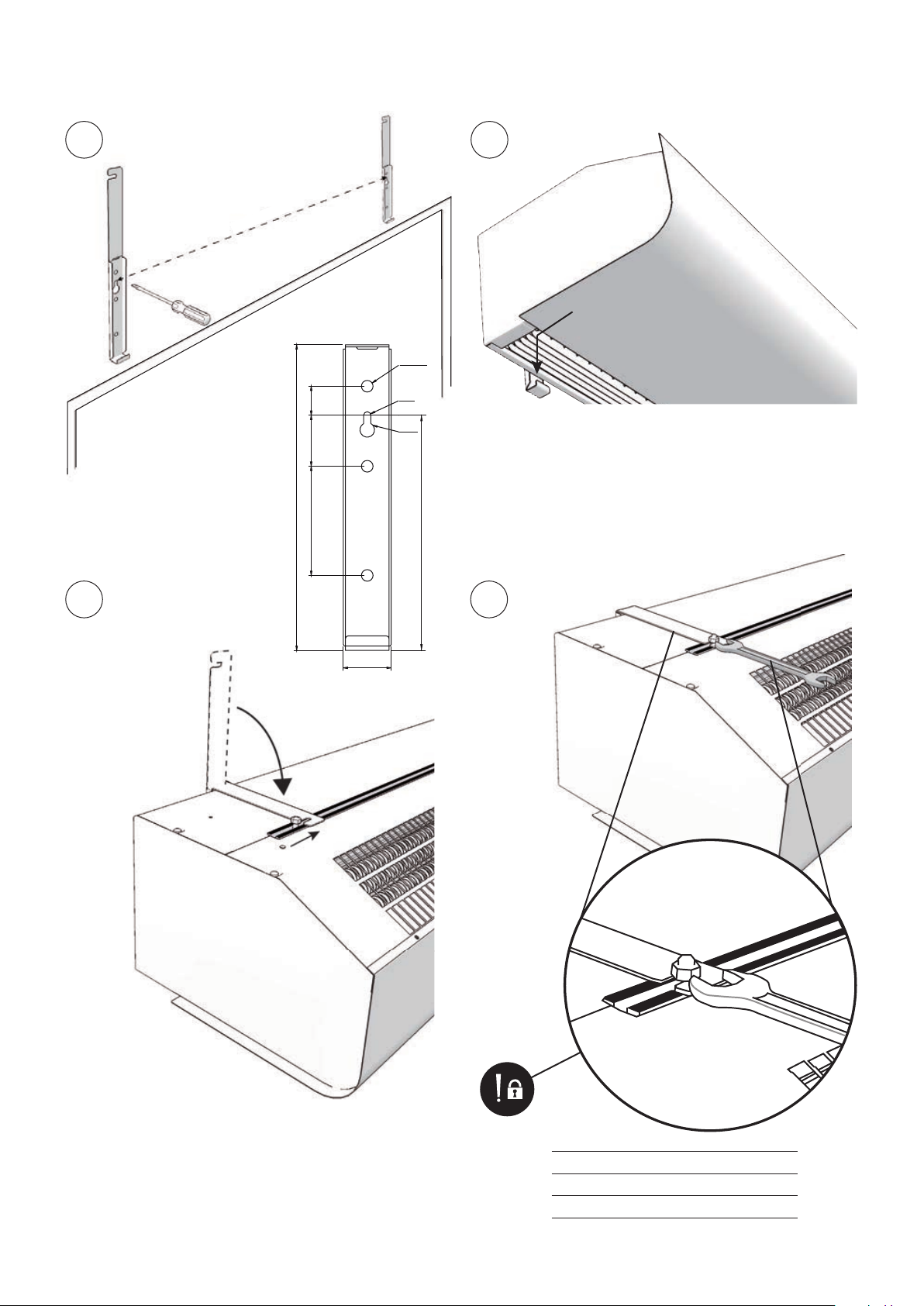
Mounting with wall brackets (g. 6)
1. Mount the brackets on the wall, see g.6A
and dimension drawing g.1. If the wall is
uneven the brackets must be compensated
for this.
2. Hook on the unit at the lower edge of the
brackets. (Fig.6B)
3. Bend the top of the console over the the unit
and slide the units screws along the rail into
the slots on the consoles. (Fig.6C) When the
bracket is bent once, it must be replaced if
bent back more than 45 °.
4. Lock the nuts against the brackets. (Fig.6D)
Horizontal mounting on the ceiling
Threaded rods, hanging brackets and ceiling
mounting brackets for ceiling mounting are
available as accessories, see accessories pages
and separate manuals.
Electrical installation
The installation, which should be preceded by
an isolator switch with a contact separation
of at least 3 mm, should only be wired by a
competent electrician and in accordance with
the latest edition of IEE wiring regulations.
The air curtain has an integrated PC board
which is connected to the selected external
control system FC. FC must be ordered
separately. The PC board is accessed via cable
glands on the top of the unit. See Fig. 2. FC is
supplied pre-programmed. Communicationand sensor cables are connected to the PC
board.
Should more than one air curtain be
controlled by a single FC, an additional
communication cable FCBC per unit will be
required. See manual for FC.
Unit without heating or with water heating
Connected via the built-in control board with
1,5 m cord and plug.
Unit with electrical heating
The electrical connection is made on the top
of the unit. Pierce the gland with a screwdriver
before entering the cable. See Fig. 2. Control
(230V~) and power supply for heat (400V3~)
should be connected to a terminal block in the
terminal box. 2-metre and longer units require
dual power supplies. See dimension drawings.
The largest cable diameter for the terminal
block is 16 mm². The cable glands used must
meet the protection class requirements. In the
distribution board, it is to be indicated that ”the
air curtains can be supplied from more than
one connection”.
13

EN
Pamir 2500
Type Output Voltage Minimum
Control
PAF2510E05 5 400V3~ 1,5
PAF2510E08 8 400V3~ 2,5
PAF2515E08 8 400V3~ 2,5
PAF2515E12 12 400V3~ 4
PAF2520E10*
PAF2520E16*
*1) 2 m units are connected with two power supplies.
2
) Dimensioning of external wiring shall comply with
*
applicable regulations and local deviations may occur.
[kW]
0 230V~ 1,5
1
5 400V3~ 1,5
5 400V3~ 1,5
1
8 400V3~ 2,5
8 400V3~ 2,5
[V]
area*
[mm2]
Start-up (E)
When the unit is used for the rst time or after
a long period of non-use, smoke or an odour
may result from dust or dirt which has collected
on the element. This is completely normal and
disappears after a short time.
Connecting the water coil (W)
The installation must be carried out by an
authorised installer.
The water coil has copper tubes with
aluminium ns and is suitable for connection
to a closed water heating system. The heating
coil must not be connected to a mains pressure
water system or an open water system.
Note that the unit shall be preceded by a
regulating valve, see Frico valve kit.
Valves must be installed outside the unit.
Note that the actuator needs power supply and
control signal from the integrated PC board.
The water coil is connected on the upper side of
the unit with ø15 mm smooth copper pipe with
a suitable coupling and internal liner. Soldering
is not recommended. The connections to the
heating coil must be equipped with shut off
valves to allow trouble-free removal. The water
coil is equipped with a drain valve. A vent valve
should be connected at a high point in the pipe
system. Air valves are not included.
NOTE: Care must be taken when
connecting the pipes. Always use an
internal liner in the pipe connections to
prevent straining of the pipes and subsequent
water leakage.
Adjustment of the air curtain and airow
The direction and speed of the airow should
be adjusted considering the load on the
opening. Pressure forces affect the airstream
and force it inwards towards the premises
(when the premises are heated and the
outdoor air is cold).
The airstream should, therefore, be directed
outwards to withstand the load. Generally
speaking, the higher the load, the greater the
angle required.
Basic setting fan speed
The fan speed when the door is open is
set using the control. Note that the airow
direction and the fan speed may need ne
adjustment depending on the loading of the
door.
Filter (W)
The water coil is protected against dirt and
blockage by an internal air lter which covers
the coil face. In environments where the lter
requires frequent cleaning, it is advisable to use
an external intake lter (see accessories pages),
which provides easier maintenance, since
the unit does not need to be opened. When
an external lter is used, the internal lter is
removed.
Service, repairs and maintenance
For all service, repair and maintenance rst
carry out the following:
1. Disconnect the power supply.
2. The front hatch is removed by removing the
screws on the top of the unit and then detach
the bent edge at the bottom. (Fig.3)
3. After the service, repair and maintenance
reattach the front hatch. Place the hatch at
the lower edge with the bent edge and fasten
on top with screws.
Note that when carrying out work where the
end is removed, the outlet grille also detaches.
Maintenance
Unit with water heating
The appliance lter should be cleaned regularly
to ensure the air curtain effect and heat
emission from the device. How often depends
on local circumstances. A clogged lter is not a
risk, but the appliance function can fail.
1. Disconnect the power supply.
2. The front hatch is removed by removing the
screws on the top of the unit and then detach
the bent edge at the bottom. (Fig.3)
3. Remove the lter and vacuum clean or wash
it. If the lter is clogged or damaged, it may
need to be changed.
14

Pamir 2500
EN
All units
Since fan motors and other components are
maintenance-free, no maintenance other than
cleaning is necessary. The level of cleaning can
vary depending on local conditions. Undertake
cleaning at least twice a year. Inlet and exhaust
grilles, impeller and elements can be vacuum
cleaned or wiped using a damp cloth. Use a
brush when vacuuming to prevent damaging
sensitive parts. Avoid the use of strong alkaline
or acidic cleaning agents.
Temperature control
Temperature control of FC maintains the
exhaust temperature. Should the temperature
exceed the preset value, the overheating alarm
will activate. For more information see the FC
manual.
Overheating
Unit with electrical heating
The air curtain unit with electrical heating is
equipped with an overheat protection. If it is
deployed due to overheating, reset as follows:
1. Disconnect the power supply with the isolator
switch.
2. Determine the cause of overheating and
rectify the fault.
3. Remove the front hatch.
4. Press the red button located inside the air
curtain unit, at the inner gable of the terminal
box.
5. Reattach the front hatch and connect the unit
again.
All units
All motors are equipped with an integral
thermal safety cut-out. This will operate,
stopping the air curtain should the motor
temperature rise too high. The cut-out
will automatically reset when the motor
temperature has returned to within the motor’s
operating limits.
Replacing heating elements/heating
package (E)
1. Mark and disconnect the cables to the
heating elements/package.
2. Remove the mounting screws securing the
heating elements/package in the unit and lift
the heating elements/package out.
3. Install the new heating elements/package in
reverse order to the above.
Replacing the water coil (W)
1. Shut off the water supply to the unit.
2. Disconnect the connections to the water coil.
3. Remove the mounting screws securing the
coil in the unit and lift out.
4. Install the new coil in reverse order to the
above.
Draining the water coil (W)
The drain valve is on the underside of the coil
on the connector side. It can be accessed via
the front hatch.
Replacing motor or impeller
1. Remove the front.
2. Remove gable end.
3. Remove the screw between motor and fan.
4. Disconnect the cables to the motor.
5. Remove the screws securing the motor and
lift it out together with the impeller.
6. Install the new motor and/or the new
impeller as above in reverse order.
Replacing the PC board
1. The PC board is located in the terminal box.
Fig. 2
2. Mark and disconnect the cables to the PC
board.
3. Remove the screws securing the board and
lift out.
4. Install the new PC board as above in reverse
order.
Troubleshooting
If the fans are not running or do not perform
properly, check the following:
• The power supply.
• That the intake grille/lter is not dirty.
• That the motor's safety cut-out has not been
deployed.
• Functions and settings of the FC control
system, see the FC manual.
If there is no heat, check the following:
• Functions and settings of the FC control
system, see the FC manual.
For units with electrical heating, also check the
following:
• Power supply to electric heater coil; check
fuses and circuit-breaker (if any).
• That the overheat protection has not been
deployed.
15

EN
Pamir 2500
For units with a water coil, also check the
following:
• That the water coil is air free.
• That there is sucient water ow and
pressure.
• That incoming water is heated adequately.
If the fault cannot be rectied, please contact a
qualied service technician.
Residual current circuit breaker (E)
When the installation is protected by means of
a residual current circuit breaker, which trips
when the appliance is connected, this may be
due to moisture in the heating element. When
an appliance containing a heater element has
not been used for a long period or stored in
a damp environment, moisture can enter the
element.
This should not be seen as a fault, but is
simply rectied by connecting the appliance to
the main supply via a socket without a safety
cut-out so that the moisture can be eliminated
from the element. The drying time can vary
from a few hours to a few days. As a preventive
measure, the unit should occasionally be run
for a short time when it is not being used for
extended periods of time.
Packaging
Packaging materials are chosen with
consideration to the environment and are
therefore recyclable.
Handling of product at end of working
life
This product may contain substances necessary
for the functionality of the product but
potentially dangerous for the environment. The
product should not be disposed of mixed with
general household waste but delivered to a
designated collection point for environmental
recycling. Please contact the local authority
for further details of your nearest designated
collection point.
Safety
• For all installations of electrically heated
products a residual current circuit breaker
300 mA for re protection should be used.
• Keep the areas around the air intake and
exhaust grilles free from possible obstructions!
• The unit must not be fully or partially covered as
overheating can result in a re risk!
• Lifting equipment must be used to lift the unit.
• This appliance can be used by children aged
from 8 years and above and persons with
reduced physical, sensory or mental capabilities
or lack of experience and knowledge if they
have been given supervision or instruction
concerning use of the appliance in a safe way
and understand the hazards involved. Children
shall not play with the appliance. Cleaning and
user maintenance shall not be made by children
without supervision.
• Children of less than 3 years should be kept
away unless continuously supervised.
• Children aged from 3 years and less than 8
years shall only switch on/off the appliance
provided that it has been placed or installed
in its intended normal operating position and
they have been given supervision or instruction
concerning use of the appliance in a safe way
and understand the hazards involved.
• Children aged from 3 years and less than 8
years shall not plug in, regulate and clean the
appliance or perform user maintenance.
CAUTION — Some parts of this product can
become very hot and cause burns. Particular
attention has to be given where children and
vulnerable people are present.
16

Main offi ce
Frico AB Tel: +46 31 336 86 00
Industrivägen 41
SE-433 61 Sävedalen mailbox@frico.se
Sweden www.frico.net
For latest updated information and information
about your local contact: www.frico.net.
Art.no 247250, 2020-11-30 HH/CH
 Loading...