

Frico PA2500C Series, PA2510CA, PA2515CE08, PA2520CE10, PA2515CA Assembly And Operating Instructions Manual
...
Instrukcja obsługi
PA2500C
GB
.... 15
PL
.... 21

PA2500C
GB
PL
The introduction pages consist mainly of pictures. For translation of the
English texts used, see the respective language pages.
Początkowe strony zawierają głównie rysunki. Tłumaczenie wykorzystanych
tekstów angielskich znajduje się na odpowiednich stronach językowych.
2

ø17, 5ø17,5
ø1
Cu ø1
PA2500C
PA2500C
2 m
W/A
1026 / 1536 / 2026
20
210
1050 / 1560 / 2050
90,5
165
40
5
53
157
184
min 500
min 500
157
min 500
10
345
157
E
Fig. 1
22
71 40
min 500
Gland
Gland
min 500
157157
Knock-out
Fig. 2
7, 5
ø32,5
ø25,5
ø20,5
Knock-out
Knock-out
Gland
3
A
B
PA2500C
TX20
C
Fig. 3: Open the unit.
4
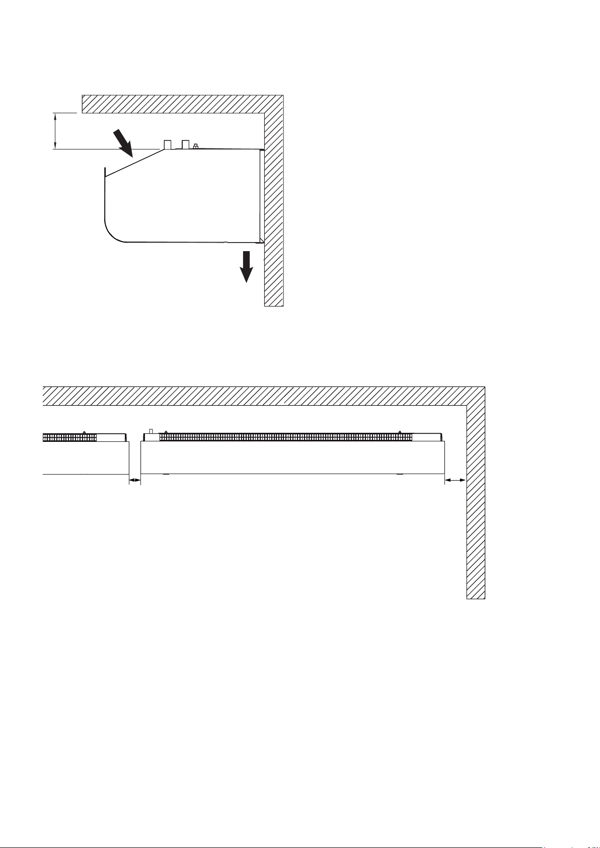
min 60
Minimum distance
Fig. 4
PA2500C
Fig. 5
30 mm
60 mm
5
210
Mounting with wall brackets
PA2500C
A
min 500 mm
B
ø8 (3x)
203575
ø5
ø10
162
C
33
D
PA2510C 2 pcs
PA2515C 2 pcs
PA2520C 3 pcs
Fig. 6: Mounting with wall brackets
6
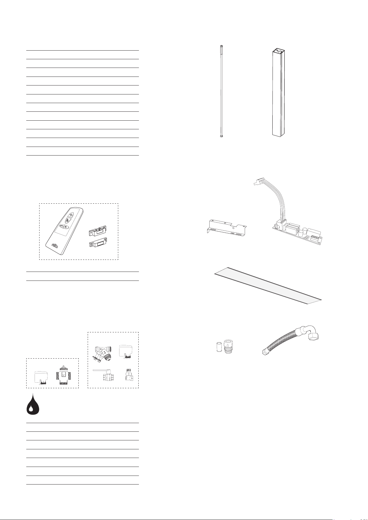
Accessories
PA34TR15 PA2510C, PA2515C, 1 m
PA34TR20 PA2520C, 1 m
PA2P15 PA2510C, PA2515C, 1 m
PA2P20 PA2520C, 1 m
PA2PF15 PA2510C, PA2515C
PA2PF20 PA2520C
PAMLK PA2500C
PA2EF10 PA2510C W
PA2EF15 PA2515C W
PA2EF20 PA2520C W
PAWAK PA2500C W
FHDN15 PA2500C W
PA2500C
PA34TR PA2P
PA2DR
VOT
PA2DR
PA2PF PAMLK
PA2EF
VOS
PAWAK FHDN15
VOT15 DN15
VOT20 DN20
VOT25 DN25
VOS15LF DN15
VOS15NF DN15
VOS20 DN20
VOS25 DN25
7

PA2500C
1 Ambient, no heat - PA2500C A
Type Output
[kW]
PA2510CA 0 900/1300 43/53 230V~ 0,5 1050 16
PA2515CA 0 1250/2100 44/54 230V~ 0,7 1560 23,5
PA2520CA 0 1800/2600 44/55 230V~ 1,0 2050 32
Airflow
[m3/h]
Sound
level*
[dB(A)]
1
3 Electrical heat - PA2500C E
Type Output
step
[kW]
PA2510CE03 2/3 900/1450 11/6,5 41/51 230V~ 0,5 230V~/13 1050 19
PA2515CE08 4/8 1400/2200 17,5/11 42/51 230V~ 0,7 400V3~/11,5 1560 30
PA2520CE10 5/10 1800/2900 17/10,5 43/53 230V~ 1,0 400V3~/14,4 2050 36
Airflow
[m3/h]
∆t
[°C]
*2
Sound
level*
[dB(A)]
2 Water heat - PA2500C W
Type Output*3
[kW]
PA2510CW 4 900/1300 10,5/8,5 0,38 41,5/50 230V~ 0,45 1050 17
PA2515CW 6,5 1250/2100 11,5/10 0,81 41/53,5 230V~ 0,6 1560 25,5
PA2520CW 8 1800/2600 11/9 0,74 44,5/54 230V~ 0,9 2050 34,5
Airflow
[m3/h]
∆t
[°C]
*2,3
Water
volume
[l]
1
Voltage
motor
[V]
Voltage
motor
[V]
Sound
level*
[dB(A)]
1
Amperage
motor
[A]
Amperage
motor
[A]
Voltage
motor
[V]
Length
[mm]
Voltage [V]
Amperage [A]
(heat)
Amperage
motor
[A]
Length
[mm]
Weight
[kg]
Length
[mm]
Weight
[kg]
Weight
[kg]
*1) Conditions: Distance to the unit 5 metres. Directional factor: 2. Equivalent absorption area: 200 m². At
lowest/highest airflow.
*2) ∆t = temperature rise of passing air at maximum heat output and lowest/highest airflow.
*3) Applicable at water temperature 60/40 °C, air temperature, in +18 °C.
Protection class for units with electrical heating: IP20.
Protection class for units without heating and units with water heating: IP21.
CE compliant.
Type C1 Mid
[mF]
PA2510CA 10 6 4
PA2515CA 14 10 4
PA2520CA 10 6 4
PA2510CE03 10 6 4
PA2515CE08 14 10 4
PA2520CE10 10 6 4
PA2510CW 10 6 4
PA2515CW 14 10 4
PA2520CW 10 6 4
C2 Low
[mF]
C2 Run
[mF]
8
PA2510CA / PA2515CA / PA2520CA
PA2500C
PA2210CA
PA2215CA
PA2510CA
PA2515CA
PA2220CA
PA2520CA
Right motorLeft motor
Only 2 m version
9

400V 3N~
230V~
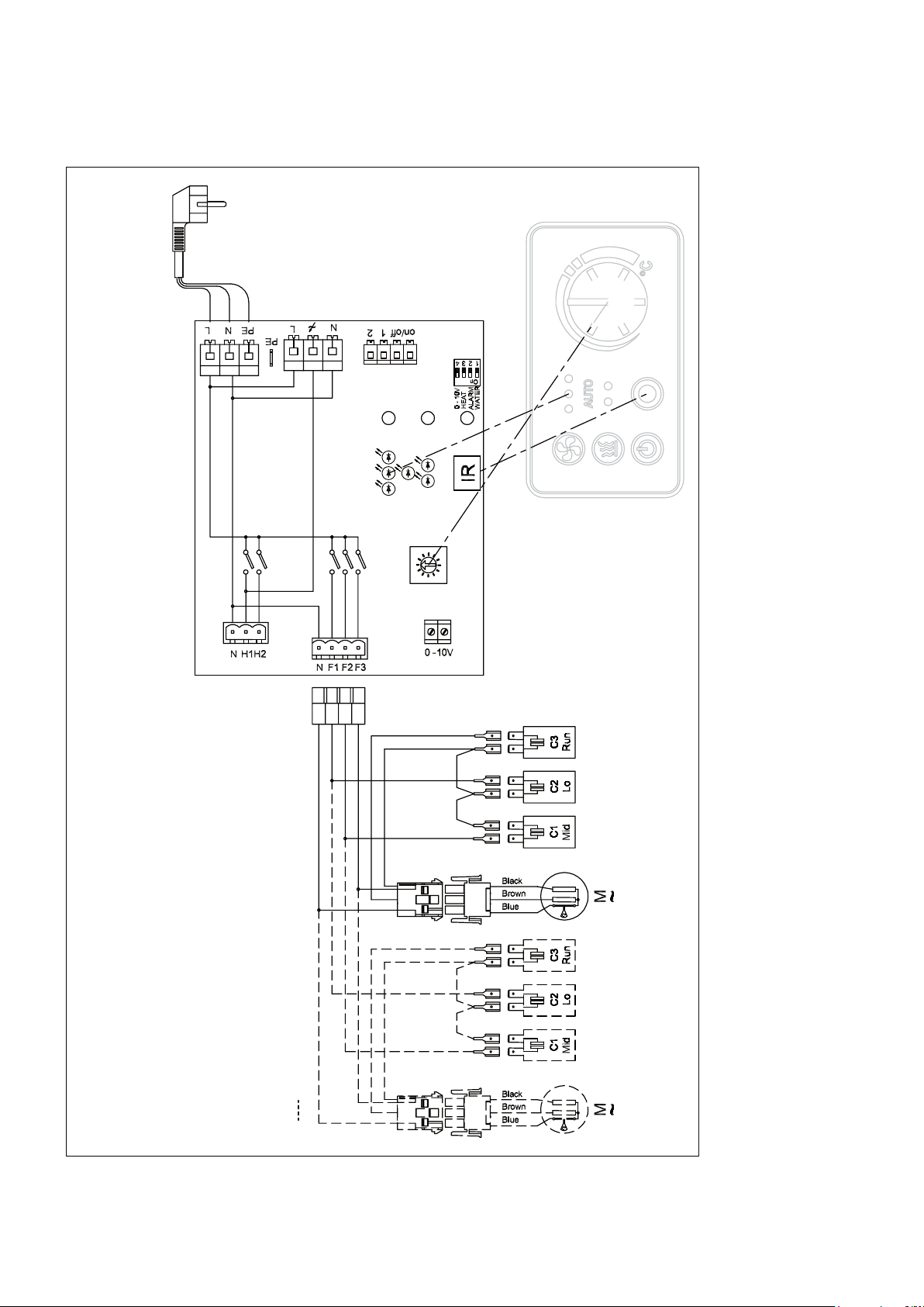
PA2510CE03
PE
NL
PA2500C
~
L
PE
N
1
on/off2
0 - 10V
HEAT
ALARM
WATER
Off
On
IR
INTERNAL
SENSOR
N
L
PE
L1
L2
L3
N
L
PE
L1
L2
L3
PA2210CE03
PA2210CE05
PA2510CE03
2210CE03
2210CE05
5A
16A
NH1H2
°C
C1
Over heat
N
cut-out
F1 F2 F3
5A x 3
0 -10V
C3
Run
C2
Lo
C1
Mid
Black
Brown
Blue
~
M
C°
10

400V 3N~
400V3~
PA2515CE08 / PA2520CE10
N
L
PE
L1
L2
L3
PA2500C
~
L
PE
N
L
PE
5A
16A
N
1
on/off2
0 - 10V
HEAT
ALARM
WATER
Off
On
IR
INTERNAL
SENSOR
5A x 3
NH1H2
°C
C1
C2
PE
L1
L2
L3
C3
C4
Over heat
°C
Over heat
cut-out
cut-out
N
F1 F2 F3
0 -10V
Black
Brown
Blue
C3
Run
C2
Lo
C1
Mid
~
M
C°
C3
Run
C2
Lo
Right motor
PA2215CE08
PA2220CE10
PA2515CE08
PA2520CE10
Only 2 m version
Black
Brown
Blue
C1
Mid
~
M
C°
Left motor
11

PA2510CW / PA2515CW / PA2520CW
Black
Brown
Blue
~
L
PE
NL
PE
N
1
on/off2
0 - 10V
HEAT
ALARM
WATER
Off
On
PA2500C
NH1H2
IR
INTERNAL
SENSOR
5A
16A
N
F1 F2 F3
5A x 3
0 -10V
C3
Run
C2
Lo
C1
Mid
Black
Brown
Blue
~
M
C°
Right motor
PA2210CW
12
PA2215CW
PA2220CW
PA2510CW
PA2515CW
PA2520CW
Only 2 m version
Black
Brown
Blue
C3
Run
C2
Lo
C1
Mid
~
M
C°
Left motor

Right motor
Left motor
~
PAMLK, motor alarm card
PA2500C
L
N
PE
N
1
on/off 2
0 - 10V
HEAT
ALARM
WATER
Off
On
IR
INTERNAL
SENSOR
L
PE
Off
On
NH1H2
5A
16A
N
NF1F2F3
PAMLK
F1 F2 F3
OUT
5A x 3
0 -10V
CNC NO
Motor alarm
(pot. free contact)
Lo
Mid
M
C°
Run
Black
Brown
Blue
~
Only 2 m version
Black
Brown
Blue
~
M
C°
Lo
Mid
Run
~
M
C°
13

Output charts water
PA2500C
Water temperature: 80/60 °C
Room temperature: +18 °C
Type Fan
position
PA2510CW max 1300 7, 2 34,3 0,09 8,2
min 900 5,8 37,3 0,07 5,5
PA2515CW max 210 0 12,0 35,2 0,15 11,1
min 1250 8,6 39,4 0,11 6,1
PA2520CW max 2600 15,1 35,1 0,18 10,1
min 1800 12,0 38,2 0,15 6,7
Type Fan
position
PA2510CW max 1300 5,6 30,6 0,07 5,3
min 900 4,4 32,9 0,05 3,6
PA2515CW max 210 0 9,4 31,4 0,11 7, 3
min 1250 6,7 34,7 0,08 4,0
PA2520CW max 2600 11,6 31,2 0,14 6,5
min 1800 9,3 33,6 0,11 4,3
Airflow
[m3/h]
Airflow
[m3/h]
Output*
[kW]
Water temperature: 70/50 °C
Room temperature: +18 °C
Output*
[kW]
Outlet
air temp.
[°C]
Outlet
air temp.
[°C]
Water
flow
[l/s]
Water
flow
[l/s]
Pressure
drop
[kPa]
Pressure
drop
[kPa]
Water temperature: 60/40 °C
Room temperature: +18 °C
Type Fan
position
PA2510CW max 1300 3,7 26,7 0,05 2,9
min 900 3,1 28,3 0,04 1,9
PA2515CW max 210 0 6,6 27,5 0,08 4,1
min 1250 4,8 29,8 0,06 2,3
PA2520CW max 2600 8,1 27,2 0,10 3,5
min 1800 6,4 28,9 0,08 2,4
Airflow
[m3/h]
Output*
[kW]
Outlet
air temp.
[°C]
Water
flow
[l/s]
Pressure
drop
[kPa]
*) Nominal output at given supply and return water temperature.
See www.frico.se for additional calculations.
14

PA2500C
Assembly and operating instructions
GB
General Instructions
Read these instructions carefully before
installation and use. Keep this manual for
future reference.
The product may only be used as set out in
the assembly and operating instructions. The
guarantee is only valid if the product is used
in the manner intended and in accordance
with the instructions.
Application area
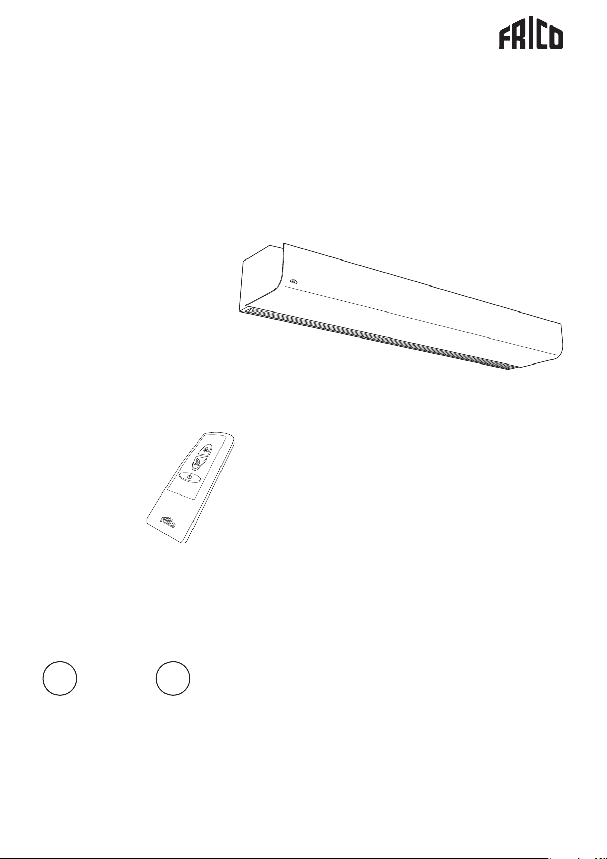
The PA2500C air curtain unit is supplied
without heating, with electrical heating or
hot water heating. PA2500C is intended for
installation heights up to 2.5 metres. The air
curtain has an integrated control system and
can be remotely controlled. Protection class
for units with electrical heating: IP20.
Protection class for units without heating and
units with water heating: IP21.
Operation
Air is drawn in at the top of the unit and
blown out downwards so that it shields the
door opening and minimizes heat loss. To
achieve the optimum curtain effect the
unit must extend the full width of the door
opening.
The grille for directing exhaust air is
adjustable and is normally angled outwards to
achieve the best protection against incoming
cold air.
The efficiency of the air curtain depends
on the air temperature, pressure differences
across the doorway and any wind pressure.
NOTE! Negative pressure in the building
considerably reduces the efficiency of the air
curtain. The ventilation should therefore be
balanced.
Mounting
The air curtain unit is installed horizontally
with the supply air grille facing downwards
as close to the door as possible. Minimum
distance from outlet to floor for electrically
heated units is 1800 mm. For other minimum
distances, see fig. 4.
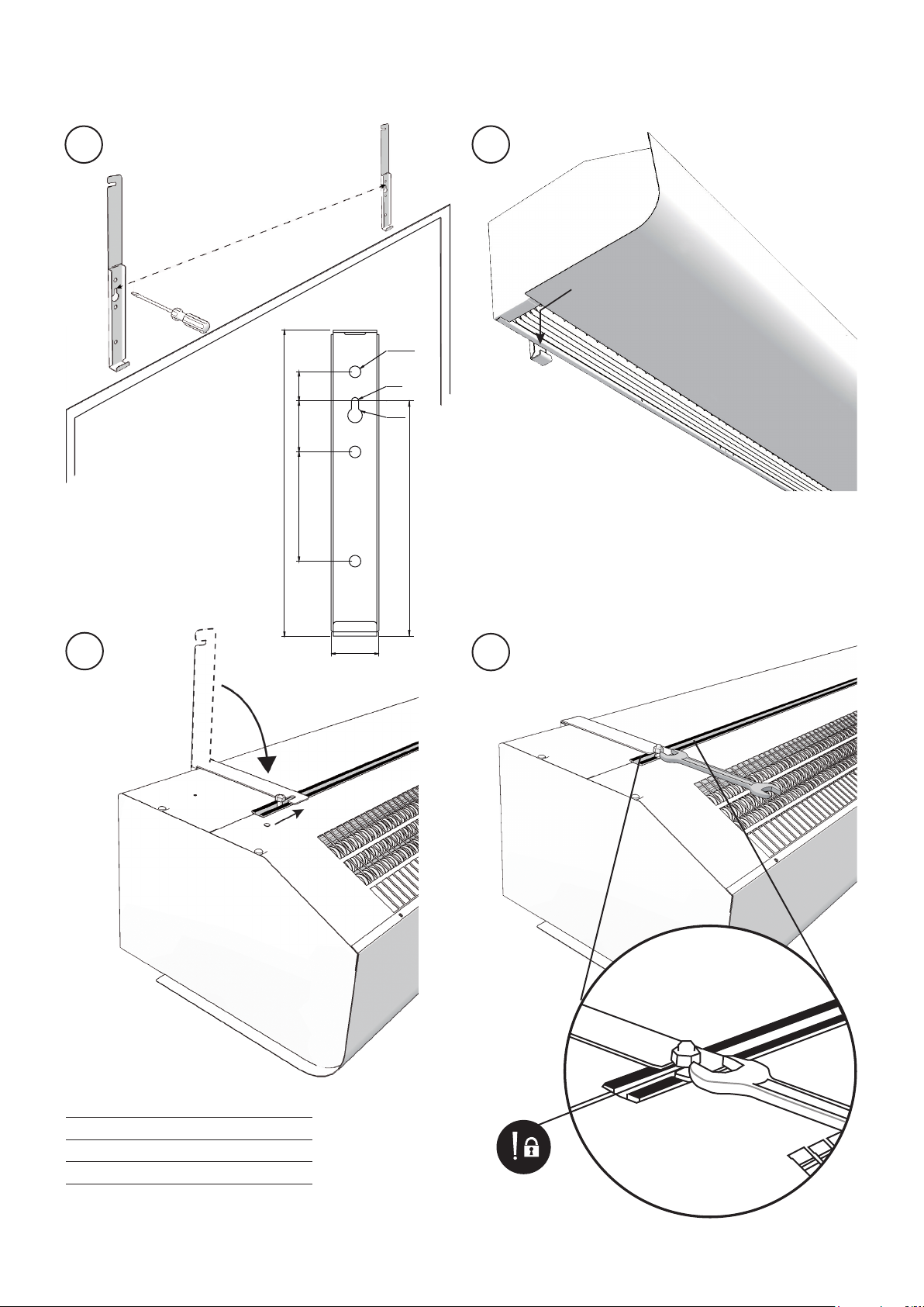
Mounting with wall brackets (fig. 6)
1. Mount the brackets on the wall, see fig.6A
and dimension drawing fig.1. If the wall is
uneven the brackets must be compensated
for this.
2. Hook on the unit at the lower edge of the
brackets. (Fig.6B-C)
3. Bend the top of the console over the the
unit and slide the units screws along the
rail into the slots on the consoles. (Fig.6D)
When the bracket is bent once, it must be
replaced if bent back more than 45 °.
4. Lock the nuts against the brackets. (Fig.6E)
Horizontal mounting on the ceiling
Threaded rods, hanging brackets and ceiling
mounting brackets for ceiling mounting are
available as accessories, see accessories pages
and separate manuals.
Electrical installation
The installation, which should be preceded by
an omnipolar switch with a contact separation
of at least 3 mm, should only be wired by a
competent electrician and in accordance with
the latest edition of IEE wiring regulations.
The control system is pre-installed in the air
curtain.
Unit without heating
Connected via the built-in control board with
1,5 m cord and plug.
Unit with water heating
Connected via the built-in control board with
1,5 m cord and plug.
Unit with electrical heating
The electrical connection is made on the
top of the unit. See Fig.2. The 3 kW unit is
connected via the integrated control card
using a 1,5 m cable and plug. Other units are
intended for permanent installation. Control
(230V~) and power supply for heat (400V3~)
should be connected to a terminal block in
the terminal box. 2-metre and longer units
require dual power supplies.
The largest cable diameter for the terminal
block is 16 mm². The cable glands used must
meet the protection class requirements. In
15

GB
PA2500C
the distribution board it is to be indicated
that ”the air curtains can be supplied from
more than one connection”.
See wiring diagrams.
Type Output
[kW]
Control 0 230V~ 1,5
PA2510CE03 3 230V~ 1,5
PA2515CE08 8 400V3~ 2,5
PA2520CE10 10 400V3~ 2,5
*) Dimensioning of external wiring shall comply
with applicable regulations and local deviations
may occur.
Voltage
[V]
Minimum
area*
[mm2]
Start-up (E)
When the unit is used for the first time or
after a long period of disuse, smoke or odour
may result from dust or dirt that has collected
on the element. This is completely normal
and disappears after a short time.
Connecting the water coil (W)
The installation must be carried out by an
authorised installer.
The water coil has copper tubes with
aluminium fins and is suitable for connection
to a closed water heating system. The heating
coil must not be connected to a mains
pressure water system or an open water
system.
Note that the unit shall be preceded by a
regulating valve, see Frico valve kit.
The water coil is connected on the upper
side of the unit with ø15 mm smooth copper
pipe with a suitable coupling or soldering.
The connections to the heating coil must be
equipped with shut off valves to allow problem
free removal. Water coil is equipped with a
drain valve. A vent valve should be connected
at a high point in the pipe system.
Air valves are not included. NOTE: Care must
be taken when connecting the pipes. Use
a wrench or similar to hold the air curtain
connections to prevent straining of the
pipes and subsequent water leakage during
connection to water supply pipe-work.
Adjustment of the air curtain and air flow
The direction and speed of the air flow should
be adjusted considering the load on the
opening. Pressure forces affect the air stream
and make it bend inwards into the premises
(when the premises are heated and the
outdoor air is cold).
The air stream should therefore be directed
outwards to withstand the load. Generally
speaking, the higher the load, the greater the
angle that is needed.
Basic setting fan speed
The fan speed when the door is open is set
using the control. Note that the air flow
direction and fan speed may need fine
adjustment depending on the loading of the
door.
Filter (W)
The water coil is protected against dirt and
blockage by an internal air filter which covers
the coil face. In environments where the filter
needs cleaning often, it is advisable to use an
external intake filter (see accessories pages),
which provides an easier maintenance, since
the unit does not need to be opened. When
an external filter is used, the internal filter is
removed.
Service, repairs and maintenance
For all service, repair and maintenance first
carry out the following:
1. Disconnect the power supply.
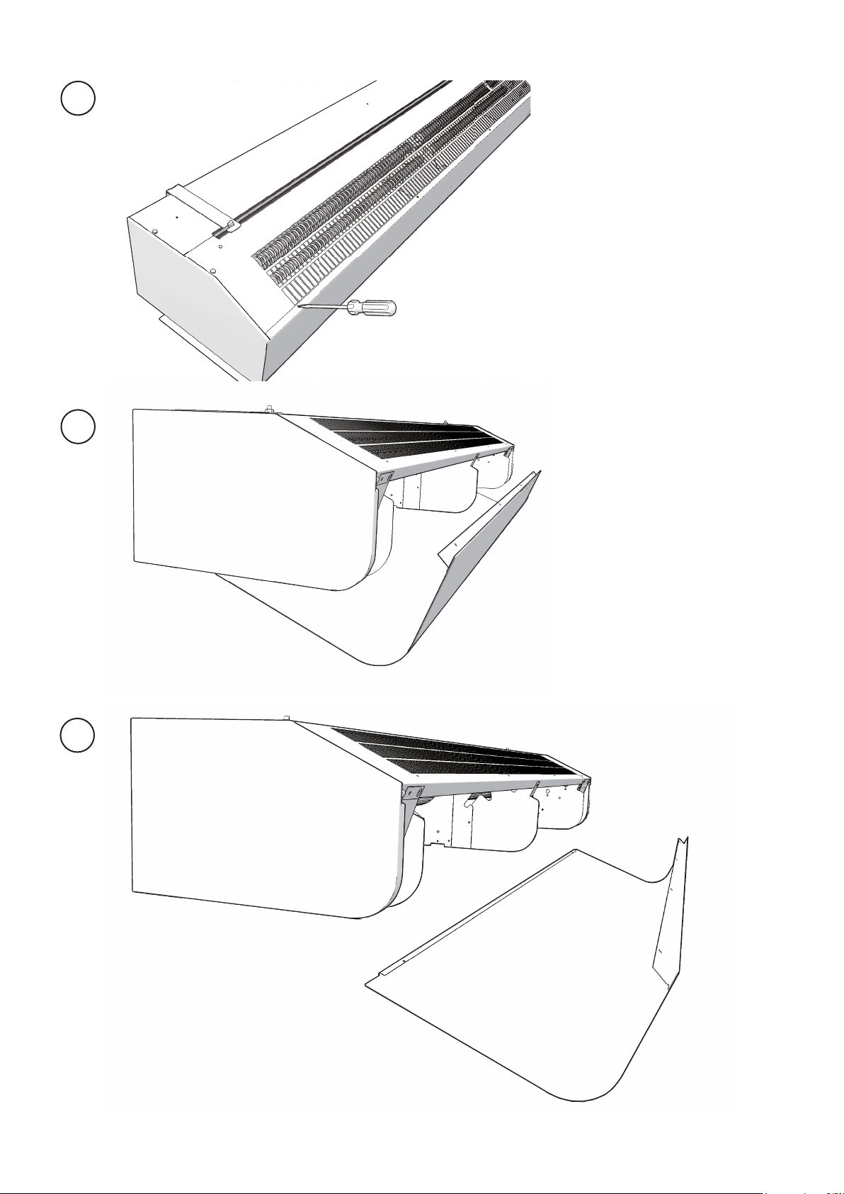
2. The front hatch is removed by removing
the screws on the top of the unit and then
detach the bent edge at the bottom. (Fig.3)
3. After the service, repair and maintenance
reattach the front hatch. Place the hatch
at the lower edge with the bent edge and
fasten on top with screws.
16

PA2500C
GB
Maintenance
Unit with water heating
The appliance filter should be cleaned
regularly to ensure the air curtain effect and
the heat emission from the device. How often
depends on local circumstances. A clogged
filter is not a risk, but the appliance function
can fail.
1. Disconnect the power supply.
2. The front hatch is removed by removing
the screws on the top of the unit and then
detach the bent edge at the bottom. (Fig.3)
3. Remove the filter and vacuum clean or
wash it. If the filter is clogged or damaged, it
may need to be changed.
All units:
Since fan motors and other components are
maintenance free, no maintenance other than
cleaning is necessary. The level of cleaning
can vary depending on local conditions.
Undertake cleaning at least twice a year. Inlet
and exhaust grilles, impeller and elements
can be vacuum cleaned or wiped using a
damp cloth. Use a brush when vacuuming
to prevent damaging sensitive parts. Avoid
the use of strong alkaline or acidic cleaning
agents.
Overheating
The air curtain unit with electric heater is
equipped with an overheat protector. If it is
deployed due to overheating, reset as follows:
1. Disconnect the electricity with the fully
isolated switch.
2. Determine the cause of overheating and
rectify the fault.
3. Remove the front hatch.
4. Press the red button located inside the
air curtain unit, at the inner gable of the
terminal box.
5. Reattach the front hatch and connect the
unit again.
Temperature control
See control pages.
Replacing motor or impeller
1. Remove gable end.
2. Remove the screw between motor and fan.
3. Disconnect the cables to the motor.
4. Remove the screws securing the motor and
lift it out together with the impeller.
5. Install the new motor and/or the new
impeller as above in reverse order.
Replacing heating elements/heating
package (E)
1. Mark and disconnect the cables to the
heating elements/package
2. Remove the mounting screws securing the
heating elements/package in the unit and
lift the heaging elements/package out.
3. Install the new heating elements/package in
reverse order to the above.
Replacing the water coil (W)
1. Shut off the water supply to the unit.
2. Disconnect the connections to the water
coil.
3. Remove the mounting screws securing the
coil in the unit and lift the coil out.
4. Install the new coil in reverse order to the
above.
Draining the water coil (W)
The drain valve is on the underside of the coil
on the connector side. It can be accessed via
the front hatch.
All motors are equipped with an integral
thermal safety cut-out. This will operate,
stopping the air curtain should the motor
temperature rise too high. The cut-out
will automatically reset when the motor
temperature has returned to within the
motor’s operating limits.
17

GB
PA2500C
Trouble shooting
If the fans are not working or do not blow properly, check the following:
• The functions and settings of the built-in
control system.
• That the intake grille/filter is not dirty.
If there is no heat, check the following:
• The functions, internal sensor and settings
of the built-in control system.
For units with electrical heating, also check the
following:
• Power supply to electric heater coil; check
fuses and circuit-breaker (if any).
• That the overheat protection for the motors
has not been deployed.
For units with water coil, also check the following:
• That the water coil is air free.
• That there is enough water flow.
• That incoming water is heated enough.
If the fault cannot be rectified, please contact
a qualified service technician.
Safety
• For all installations of electrically heated
products should a residual current circuit
breaker 300 mA for fire protection be used.
• Keep the areas around the air intake
and exhaust grilles free from possible
obstructions!
• The unit may have hot surfaces during
operation and when cooling down!
• The unit must not be fully or partially
covered with clothing, or similar
materials, as overheating can result in a
fire risk! (E)
• This appliance can be used by children
aged from 8 years and above and persons
with reduced physical, sensory or
mental capabilities or lack of experience
and knowledge if they have been given
supervision or instruction concerning
use of the appliance in a safe way and
understand the hazards involved. Children
shall not play with the appliance. Cleaning
and user maintenance shall not be made
by children without supervision.
Residual current circuit breaker (E)
When the installation is protected by means
of a residual current circuit breaker, which
trips when the appliance is connected,
this may be due to moisture in the heating
element. When an appliance containing a
heater element has not been used for a long
period or stored in a damp environment,
moisture can enter the element.
This should not be seen as a fault, but is
simply rectified by connecting the appliance
to the main supply via a socket without a
safety cut-out, so that the moisture can be
eliminated from the element. The drying
time can vary from a few hours to a few days.
As a preventive measure, the unit should
occasionally be run for a short time when it is
not being used for extended periods of time.
18

Controls
The air curtain has an integrated control
system and can be remotely controlled.
PA2500C
GB
230V~
Black
Brown
Blue
PA2DR
(accessory)
External on/off
Eg time switch.
External potential
free closure = off
ON
4
3
Actuator SD230
(remove the quick
connector)
OFF
21
4
3
3
2
2
ON
Factory setting dip-switches - Unit without heating
or with electrical heating
Dip-switch 3 is used for PA2DR (optional).
1
ON
Factory setting dip-switches - Unit with water
heating
Dip-switch 3 is used for PA2DR (optional).
1
19

GB
PA2500C
Fan step 1/2/3
Heat step
Electric: Half/full power
Water: On/off (1 LED)
On/off
Fan step 1/2/3
On/off
~20 °C
3
2
Control panel - Unit with electrical heating or water
heating
Control panel - Unit without heating
Remote control - on/off, fan steps and heating steps
Functional test
Functional test is started using the remote
control.
Push
and
1
Temperature control
If the temperature exceeds 50 °C, the fan
runs at full speed for 2 minutes to vent out
the heat, if the temperature rises above
50 °C again during the following 5 minutes
overheating alarm is deployed. The red LEDs
flash and all the buttons are locked.
in 5 seconds
Fan and heatings steps are tested in
10-second intervals which is indicated by
lighted LEDs. When the test is completed, all
LEDs will flash for 30 seconds.
20
1. Disconnect the electricity with the fully
isolated switch.
2. Determine the cause of overheating and
rectify the fault.
3. Connect the unit again.

PA2500C
Instrukcja montażu i obsługi
PL
Zalecenia ogólne
Przed rozpoczęciem montażu i eksploatacji należy
uważnie przeczytać niniejszą instrukcję obsługi.
Instrukcję należy zatrzymać do przyszłych konsultacji.
Produkt może być używany tylko zgodnie z
zaleceniami podanymi w instrukcji montażu i obsługi.
Produkt podlega gwarancji wtedy i tylko wtedy, gdy
jest eksploatowany zgodnie z jego przeznaczeniem i
instrukcją.
Zastosowanie
Kurtyna powietrzna PA2500C występuje w wersji
bez ogrzewania, z grzałkami elektrycznymi lub z
wymiennikiem wodnym. Model PA2500C jest
przeznaczony do montażu na wysokości do 2,5 m.
Urządzenie posiada zintegrowany układ sterowania
i można nim sterować zdalnie. Stopień ochrony
urządzeń z grzałkami elektrycznymi: IP20.
Stopień ochrony dla urządzeń bez ogrzewania i
urządzeń z wymiennikiem wodnym: IP21.
Praca
Powietrze jest zasysane z góry urządzenia i
wydmuchiwane na dół, tworząc ekran powietrzny
wzdłuż płaszczyzny drzwi i minimalizując straty
ciepła. Największą sprawność uzyskuje się, gdy kurtyna
pokrywa całą szerokość otworu.
Kratka wylotowa do sterowania strumieniem
powietrza posiada regulację i aby zapewnić jak
najlepszą ochronę przed napływającym zimnym
powietrzem, zazwyczaj kieruje się ją na zewnątrz.
Efektywność kurtyny powietrznej zależy od różnicy
temperatur i ciśnień w obszarze wejściowym oraz od
naporu wiatru.
UWAGA! Podciśnienie w budynku znacznie obniża
sprawność kurtyny powietrznej. Dlatego należy
odpowiednio zbilansować wentylację!
Montaż
Kurtynę powietrzną montuje się poziomo z kratką
nadmuchową skierowaną w dół, tak blisko drzwi,
jak to możliwe. Minimalna odległość od wylotu
do podłogi w przypadku urządzeń z grzałkami
elektrycznymi wynosi 1800 mm. Pozostałe minimalne
odległości, patrz Rys. 4.
Montaż przy użyciu uchwytów ściennych (Rys. 6)
1. Przymocuj wsporniki do ściany – patrz rys. 6A oraz
rysunek wymiarowy rys. 1. Jeśli ściana jest nierówna,
wsporniki należy odpowiednio dopasować.
2. Zawieś urządzenie na dolnej krawędzi wsporników
(rys. 6B-C).
3. Wygnij górną część konsoli nad urządzeniem i wsuń
śruby urządzenia wzdłuż prowadnicy w otwory
w konsolach (rys. 6D). Jeśli wygięty wspornik
odgina się pod kątem większym niż 45°, należy go
wymienić.
4. Dokręć nakrętki do wsporników (rys. 6E).
Montaż poziomy pod sutem
Pręty gwintowane, wsporniki do montażu
podwieszanego i sufitowego są dostępne jako
wyposażenie dodatkowe – patrz strony z opisem
wyposażenia dodatkowego oraz oddzielne instrukcje.
Podłączenie elektryczne
Kurtyna powinna być izolowana elektrycznie za
pomocą wyłącznika wielobiegunowego o minimalnym
odstępie między stykami 3 mm. Urządzenie powinno
być podłączane tylko przez wykwalifikowanego
elektryka, zgodnie z obowiązującymi przepisami
elektrycznymi. Układ sterowania został zainstalowany
fabrycznie w kurtynie powietrznej.
Urządzenie bez ogrzewania
Podłączane przez wbudowaną kartę sterującą za
pomocą 1,5-metrowego przewodu z wtyczką.
Urządzenie z wymiennikiem wodnym
Podłączane przez wbudowaną kartę sterującą za
pomocą 1,5-metrowego przewodu z wtyczką.
Urządzenie z grzałkami elektrycznymi
Podłączenie elektryczne wykonuje się na górnej ścianie
urządzenia. Patrz Rys.2. Urządzenia o mocy 3 kW
podłącza się przez zintegrowaną kartę sterującą za
pomocą kabla o długości 1,5 m zakończonego wtyczką.
W pozostałych modelach zasilanie dorowadzane jest
do skrzynki podłączeniowej. Sterowanie (230V~)
i zasilanie grzałek (400V3~) należy podłączyć do
zacisku na listwie zaciskowej w skrzynce zaciskowej.
Urządzenia o długości 2 m i większej wymagają
podwójnego zasilania.
Największa średnica przewodu podłączanego do
listwy zaciskowej wynosi 16 mm². Użyte dławiki
kablowe muszą zapewniać wymagany stopień ochrony.
Na tablicy rozdzielczej należy umieścić ostrzeżenie:
„Kurtyny powietrze mogą być zasilane z kilku źródeł”.
Patrz schematy elektryczne.
21

PL
PA2500C
Typ Moc
[kW]
Sterowanie 0 230V~ 1,5
PA2510CE03 3 230V~ 1,5
PA2515CE08 8 400V3~ 2,5
PA2520CE10 10 400V3~ 2,5
*) Wymiarowanie zewnętrznego okablowania powinno
spełniać obowiązujące przepisy. Dopuszcza się lokalne
odchylenia.
Napięcie
[V]
Min. przekrój
przewodu*
[mm2]
Uruchamianie (E)
Przy pierwszym użyciu lub po długim okresie przerwy
w eksploatacji urządzenia może pojawić się dym lub
nieokreślony zapach z powodu nagromadzenia się
kurzu lub zanieczyszczeń na elemencie grzejnym. To
całkowicie normalne zjawisko, które ustąpi po krótkim
czasie.
Podłączanie wymiennika wodnego (W)
Instalacja powinna zostać wykonana przez osobę
posiadającą odpowiednie uprawnienia.
Wymiennik wodny kurtyny składa się z
aluminiowych radiatorów oraz wężownicy miedzianej.
Wymiennik jest przystosowany do podłączania tylko
do zamkniętych układów hydraulicznych. Wężownicy
grzejnej nie wolno podłączać do ciśnieniowych ani
otwartych układów hydraulicznych.
Przed urządzeniem należy zainstalować zawór
sterujący, patrz zestaw zaworów firmy Frico.
Wężownicę wodną podłącza się w górnej części
urządzenia, wykorzystując gładko zakończony
króciec miedziany o średnicy ø15 mm, za pomocą
odpowiedniej złączki lub lutowania. Podłączenia
wężownicy grzejnej powinny być wyposażone
w zawory odcinające, umożliwiające swobodny
demontaż. Wymiennik wodny wyposażony jest w
zawór spustowy. W najwyższym punkcie instalacji
rurowej należy zainstalować zawór odpowietrzający.
Zawory powietrzne nie znajdują się na wyposażeniu.
UWAGA: Zachować ostrożność przy podłączaniu
wymiennika. Należy użyć drugiego klucza do
zablokowania króćca aby uniknąć jego przekręcenia i
ewentualnej nieszczelności podłączenia.
Dlatego należy skierować strumień na zewnątrz,
aby stawiał opór naporowi powietrza zewnętrznego.
Generalnie im napór jest większy, tym większy należy
ustawić kąt.
Podstawowa regulacja prędkości
wentylatorów
Prędkość wentylatora przy otwartych drzwiach ustawia
się za pomocą regulatora. Należy pamiętać, że kierunek
strumienia powietrza i prędkość wentylatora mogą
wymagać dodatkowej regulacji, zależnie od naporu
powietrza zewnętrznego na wejście.
Filtr (W)
Wymiennik wodny jest chroniony przed brudem i
zapchaniem przez wewnętrzny filtr powietrza, który
przykrywa powierzchnię wymiennika. W warunkach,
gdzie filtr wymaga częstego czyszczenia, zaleca
się stosowanie filtra zewnętrznego czerpni (patrz
wyposażenie dodatkowe), który umożliwia łatwiejszą
konserwację, ponieważ nie wymaga otwierania
urządzenia. W przypadku zastosowania filtra
zewnętrznego należy usunąć filtr wewnętrzny.
Serwis, naprawy i konserwacja
Przy wszystkich pracach serwisowych, naprawczych i
konserwacyjnych przede wszystkim:
1. Odłącz zasilanie.
2. Przednią pokrywę zdejmuje się, odkręcając śruby na
wierzchu urządzenia i wyczepiając wygiętą krawędź
przy spodzie (rys. 3).
3. Po zakończeniu serwisowania, napraw i konserwacji
należy ponownie zamocować przednią pokrywę.
Zaczep wygiętą krawędź pokrywy o dolną krawędź,
po czym wkręć górne śruby.
Regulacja kurtyny powietrznej i strumienia
powietrza
Kierunek i prędkość przepływu powietrza należy
wyregulować odpowiednio do różnicy temperatur,
różnicy ciśnień i naporu wiatru zabezpieczanego
wejścia. Podciśnienie sprawia, że powietrze napływa do
budynku, kiedy budynek jest ogrzewany, a temperatura
zewnętrzna jest niska.
22

PA2500C
PL
Konserwacja
Urządzenie z wymiennikiem wodnym
Filtr urządzenia należy regularnie czyścić, aby zapewnić
skuteczność kurtyny powietrznej oraz umożliwić
emisję ciepła przez urządzenie. Częstotliwość zależy
od warunków lokalnych. Zapchany filtr nie stwarza
zagrożenia, choć może niekorzystnie wpływać na
działanie urządzenia.
1. Odłącz zasilanie.
2. Przednią pokrywę zdejmuje się, odkręcając śruby na
wierzchu urządzenia i wyczepiając wygiętą krawędź
przy spodzie (rys. 3).
3. Wyjmij filtr, a następnie odkurz go lub wypierz. Jeśli
filtr jest zapchany lub uszkodzony, może wymagać
wymiany.
Wszystkie urządzenia:
Ponieważ silniki wentylatorów i inne podzespoły
są bezobsługowe, nie jest wymagana żadna inna
konserwacja poza czyszczeniem. Zakres czyszczenia
zależy od warunków lokalnych. Czyszczenie należy
przeprowadzać co najmniej dwa razy w roku. Kratkę
wlotową i wylotową, wirniki i pozostałe elementy
można czyścić odkurzaczem lub wycierać wilgotną
szmatką. Podczas odkurzania należy używać szczotki,
aby nie uszkodzić delikatnych części. Nie wolno
stosować silnych środków alkalicznych ani kwasowych.
Wymiana silnika lub wirnika
1. Usuń przednią część.
2. Wykręć śrubę między silnikiem i wentylatorem.
3. Odłącz okablowanie od silnika.
4. Wykręć śruby mocujące silnik i wymontuj go razem
z wirnikiem.
5. Zamontuj nowy silnik i/lub nowy wirnik,
wykonując powyższe czynności w odwrotnej
kolejności.
Wymiana grzałki elektrycznej/kurtyny
elektryczne (E)
1. Oznacz i odłącz przewody elementów grzejnych/
pakietu ogrzewania
2. Wykręć śruby mocujące elementy grzejne/pakiet
ogrzewania w urządzeniu, po czym wyjmij je z
obudowy.
3. Zainstaluj nowe elementy grzejne/pakiet
ogrzewania, wykonując powyższe czynności w
odwrotnej kolejności.
Wymiana wymiennika wodnego (W)
1. Odetnij dopływ wody do urządzenia.
2. Odłącz przyłącza wymiennika wodnego.
3. Wykręć śruby mocujące wymiennik w urządzeniu,
po czym wyjmij go z obudowy.
4. Zamontuj nowy wymiennik, powtarzając powyższe
czynności w odwrotnej kolejności.
Przegrzanie
Kurtyna powietrzna z grzałkami elektrycznymi jest
wyposażona w zabezpieczenie przed przegrzaniem.
Jeśli zabezpieczenie zadziała w wyniku przegrzania,
należy je zresetować w następujący sposób:
1. Odłącz zasilanie za pomocą całkowicie izolowanego
wyłącznika.
2. Ustal przyczynę przegrzania i usuń usterkę.
3. Zdejmij przednią pokrywę.
4. Naciśnij czerwony przycisk umieszczony wewnątrz
kurtyny powietrznej przy wewnętrznej stronie
szczytowej skrzynki rozdzielczej.
5. Zamocuj przednią pokrywę i ponownie podłącz
urządzenie.
Wszystkie silniki są wyposażone w zintegrowany
termiczny wyłącznik bezpieczeństwa, który
zadziała, wyłączając kurtynę powietrzną, jeśli
temperatura silnika nadmiernie wzrośnie. Wyłącznik
automatycznie zresetuje się, kiedy temperatura silnika
powróci do dozwolonego zakresu.
Opróżnianie wymiennika wodnego (W)
Zawory spustowe znajdują się na spodzie wymiennika
po stronie przyłącza. Dostęp do zaworów odbywa się
przez pokrywę serwisową.
Regulacja temperatury
Patrz strony dotyczące sterowania.
23

PL
PA2500C
Rozwiązywanie problemów
Jeśli wentylator nie działa lub działa nieprawidłowo,
sprawdź następujące punkty:
• Funkcje i ustawienia wbudowanego układu
sterowania.
• Czy kratka wlotowa/filtr nie są brudne?
Jeśli nie działa funkcja grzania, należy sprawdzić
następujące elementy:
• Funkcje, czujnik wewnętrzny i ustawienia
wbudowanego układu sterowania.
W kurtynach z grzałkami elektrycznymi sprawdź ponadto:
• Zasilanie grzałek elektrycznych, bezpieczniki i
wyłącznik (jeśli występują).
• Czy nie zadziałało zabezpieczenie termiczne
silników?
W kurtynach z wymiennikiem wodnym sprawdź ponadto:
• Czy wymiennik wodny jest odpowietrzony?
• Czy jest wystarczający przepływ czynnika
grzewczego?
• Czy temperatura czynnika grzewczego jest
wystarczająca?
Bezpieczeństwo
• Wszystkie produkty z grzałkami elektrycznymi
należy wyposażyć w wyłącznik przeciwporażeniowy
różnicowo-prądowy o mocy 300 mA jako
zabezpieczenie przeciwpożarowe.
• Przestrzeń wokół kratek wlotowych i wylotowych
nie powinna być niczym zablokowana!
• W trakcie pracy i stygnięcia powierzchnie
urządzenia mogą być gorące!
• Nie wolno całkowicie ani częściowo przykrywać
urządzenia tkaninami, ponieważ przegrzanie może
doprowadzić do pożaru! (E)
• Urządzenie może być obsługiwane przez dzieci
wwieku 8lat istarsze oraz osoby oograniczonej
sprawności fizycznej, sensorycznej lub umysłowej,
nie mające odpowiedniego doświadczenia lub
wiedzy, jeśli znajdują się pod nadzorem lub zostały
przeszkolone wzakresie bezpiecznej obsługi
urządzenia izdają sobie sprawę zwystępujących
zagrożeń. Dzieci nie powinny używać urządzenia
do zabawy. Czyszczenie ikonserwacja prowadzona
przez użytkownika nie powinny być wykonywane
przez dzieci bez nadzoru.
Jeśli usterki nie można usunąć, należy skontaktować się
z wykwalifikowanym serwisantem.
Wyłącznik przeciwporażeniowy różnicowoprądowy (E)
Jeśli instalacja jest zabezpieczona wyłącznikiem
przeciwporażeniowym różnicowo-prądowym, który
załącza się po podłączeniu urządzenia, przyczyną
może być wilgotny element grzejny. Jeśli urządzenie
zawierające element grzejny nie było używane przez
dłuższy okres czasu i jest przechowywane w miejscu
o wysokiej wilgotności powietrza, może dojść do
zawilgocenia elementu grzejnego.
Nie należy tego traktować jako usterki, ponieważ
wystarczy podłączyć urządzenie do zasilania przez
gniazdko bez wyłącznika bezpieczeństwa, aby usunąć
wilgoć. Czas schnięcia może wynosić od kilku godzin
do kilku dni. Aby zapobiec takiej sytuacji, jeśli
urządzenie nie jest używane przez dłuższy okres czasu,
należy je regularnie uruchamiać.
24

PA2500C
Sterowanie
Urządzenie posiada zintegrowany układ sterowania i
można nim sterować zdalnie.
PL
230V~
Czarny
Brązowy
Niebieski
PA2DR
(wyposażenie dodatkowe)
Zewn. wł./wył.
np. wył. czasowy.
Zewnętrzny styk
bezpotencjałowy = wył.
WŁ.
4
3
Siłownik SD230
(usunąć szybkozłącze)
WYŁ.
21
4
3
3
2
2
ON
Przełączniki ustawione fabrycznie - Urządzenie bez
ogrzewania lub z grzałkami elektrycznymi
Przełącznik 3 przeznaczony do obsługi czujnika
drzwiowego (PA2DR) (opcjonalny).
1
ON
Przełączniki ustawione fabrycznie - Urządzenie z
wymiennikiem wodnym
Przełącznik 3 przeznaczony do obsługi czujnika
drzwiowego (PA2DR) (opcjonalny).
1
25

PL
PA2500C
Stopień wentylatora 1/2/3
Stopień ogrzewania
Elektryczne: połowa mocy/ pełna moc
Wodne: wł./wył. (1 dioda)
Wł./wył.
Stopień wentylatora 1/2/3
Wł./wył.
~20 °C
3
2
Panel sterowania - Urządzenia z grzałkami elektrycznymi lub
wymiennikiem wodnym
Panel sterowania - Urządzenie bez ogrzewania
Zdalne sterowanie - wł./wył., stopnie wentylatora i stopnie
ogrzewania
Test funkcjonalny
Test funkcjonalny jest uruchamiany pilotem zdalnego
sterowania.
Naciśnij
i
1
Regulacja temperatury
Jeśli temperatura przekroczy 50°C, wentylator będzie
pracować z pełną prędkością przez 2 minuty, aby
odprowadzić ciepło. Jeśli w ciągu kolejnych 5 minut
temperatura ponownie przekroczy 50°C, uruchomi
się alarm przegrzania. Czerwone diody LED będą
pulsować i wszystkie przyciski zostaną zablokowane.
w ciągu 5 sekund
Stopnie wentylatora i ogrzewania są testowane co 10
sekund, co sygnalizują diody LED. Po zakończeniu
testu wszystkie diody LED będą pulsować przez 30
sekund.
26
1. Odłącz zasilanie za pomocą całkowicie izolowanego
wyłącznika.
2. Ustal przyczynę przegrzania i usuń usterkę.
3. Podłącz urządzenie ponownie.

Tłumaczenie początkowych stron
PA2500C
PL
Gland
Open the unit
Minimum distance
Mounting with wall brackets
Pcs
Accessories
=
Dławik
=
Otwieranie urządzenia
=
Minimalne odległości
=
Montaż przy użyciu uchwytów ściennych
=
Szt.
=
Wyposażenie dodatkowe
Dane techniczne
Output steps [kW]
Output*4 [kW]
Airflow*1 [m3/h]
Sound level*2 [dB(A)]
Voltage motor [V]
Amperage motor [A]
Voltage / Amperage heat
Water volume [l]
Length [mm]
Weight [kg]
*1) Najniższy/najwyższy przepływ powietrza dla wszystkich 3 stopni wentylatora.
*2) Warunki: Odległość do urządzenia 5 m. Współczynnik kierunkowy: 2. Powierzchnia absorpcji: 200 m². Przy najniższym/
najwyższym przepływie powietrza.
*3) ∆t = przyrost temperatury przy maksymalnej mocy grzewczej i najniższym/najwyższym przepływie powietrza.
*4) Przy temperaturze wody 80/60 ºC, temperatura powietrza +18 ºC.
Stopnie mocy
=
Moc
=
Wydajność powietrza
=
Poziom głośności
=
Napięcie silnika
=
Natężenie silnika
=
Napięcie / Natężenie grzałki
=
Pojemność wymiennika
=
Długość
=
Masa
=
Stopień ochrony urządzeń z grzałkami elektrycznymi: IP20.
Stopień ochrony dla urządzeń bez ogrzewania i urządzeń z wymiennikiem wodnym: IP21.
Certyfikat CE.
Tabele mocy
Temperatura wody zasilającej
Supply water temperature [°C]
Room temperature [°C]
Outlet air temperature*1 [°C]
Water temperature [°C]
Fan position
Airflow [m3/h]
Output*2 [kW]
Return water temperature [°C]
Water flow [l/s]
Pressure drop [kPa]
*1) Zalecana temperatura wydmuchiwanego powietrza, która zapewni dobry komfort i optymalną wydajność.
*2) Nominalna wydajność przy określonej temperaturze wody zasilającej i powrotnej.
=
Temperatura pomieszczenia
=
Temperatura wydmuchiwanego powietrza
=
Temperatura wody
=
Prędkość
=
Wydajność powietrza
=
Moc
=
Temperaturze wody powrotnej
=
Przepływ wody
=
Spadek ciśnienia
=
Dodatkowe obliczenia można znaleźć na stronie www.frico.pl.
27

Main offi ce
Frico AB Tel: +46 31 336 86 00
Box 102
SE-433 22 Partille mailbox@frico.se
Sweden www.frico.se
For latest updated information and information
about your local contact: www.frico.se
Art.no 208852, 20160811 HH/SL
 Loading...