

Ceiling fans
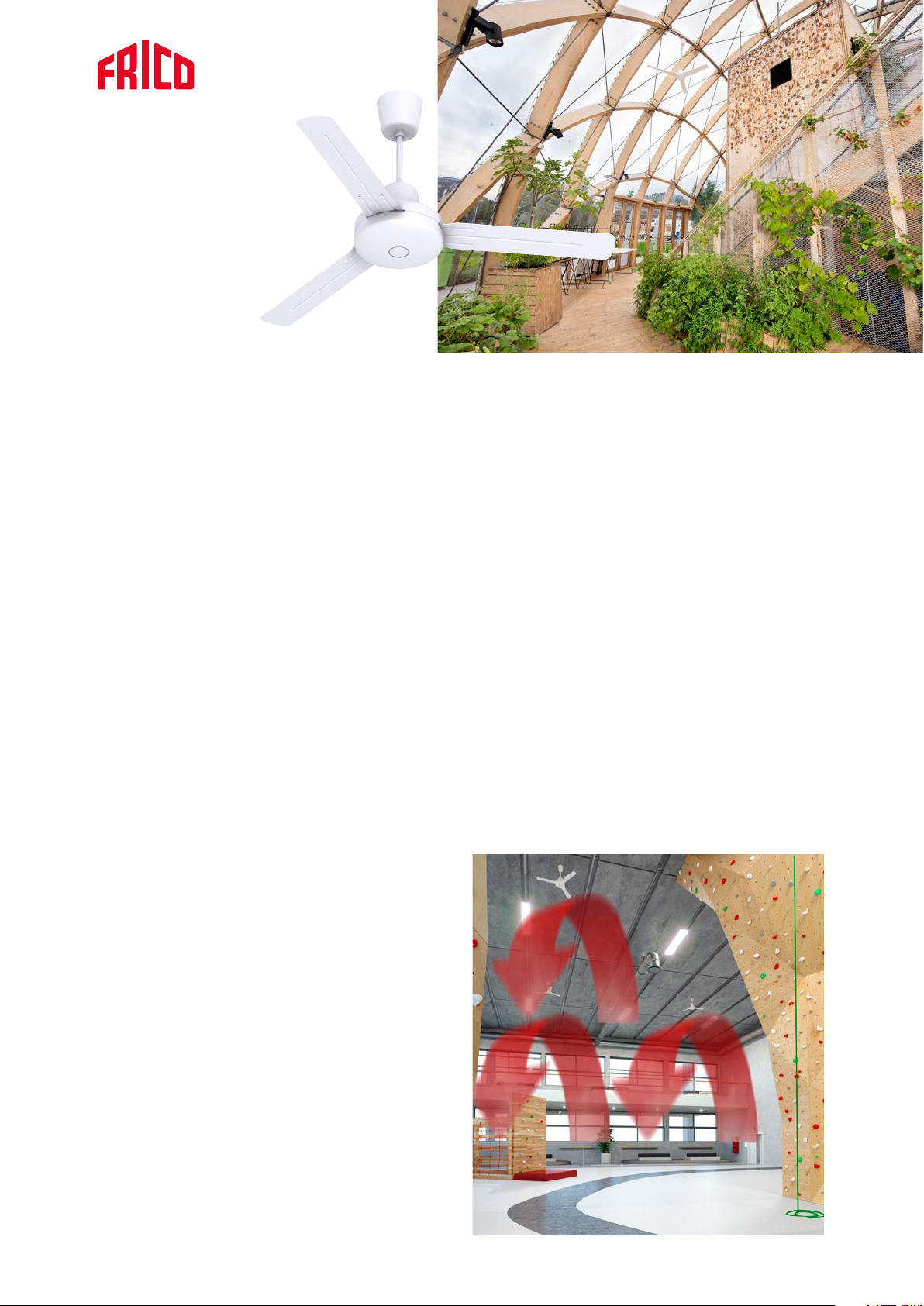
Industrial ceiling fan ICF
Equalizes the temperature in buildings with high ceilings
Application
Ceiling fans are used primarily to equalize the
temperature in rooms with high ceilings, such as
industrial and warehouse buildings, gymnasiums, and
shops. Several controls as well as downrods and blades
of different sizes are available, making it possible to
adapt ceiling fan ICF to almost all applications.
Comfort
Warm air is lighter than cold air and therefore rises
towards the ceiling. In buildings with high ceilings, a
cushion of warm air builds under the ceiling. Ceiling
fan ICF pushes down the heated air at a low speed. In
this way, the heat is better utilised in the occupied zone
without draughts. Ceiling fan ICF can rotate in both
ways, an advantage when installed at a low height.
Operation and economy
Ceiling fan ICF pushes the warm air from the ceiling
and thus lowers the temperature there, the heat losses
through the roof and walls are reduced and in many
cases, heating costs can be reduced by up to 30%.
Industrial ceiling fan ICF is of high quality and
maintenance free with a long service life.Easy
installation and low energy consumption gives a very
short pay-off period, in many instances in less than a
year.
Product specifications
• The blades push down large volumes of air without
causing excessive air speed.
• Can operate clockwise and anti-clockwise.
• Canopy with vibration absorption.
• Fan blades and downrod coated with zinc.
• The enclosed motor is equipped with permanently
lubricated ball bearings for long life.
• Other fan blade diameters are available as an
accessory (914, 1218 mm).
• Other downrods are available as an accessory (gives a
total height of 395, 945 mm).
• High protection class, IP55 (ICF55).
• Colour: NCS S 0505-R90B
Design
Industrial ceiling fan ICF has a functional design and
white colour which blends well in most premises. The
low sound level makes it even more discreet.
2020-04-03
Reduces heat losses with up to 30 %.
a
a
/2
/2
Industrial ceiling fan ICF
Technical specifications
Industrial ceiling fan ICF (IP20 / IP55)
Type Output
[W]
ICF20 70 13500 230V~ 0.33 545x1422 6.2
ICF55 70 13500 230V~ 0.33 545x1422 6.2
Protection class ICF20: IP20.
Protection class ICF55: IP55.
Approved by IMQ.
Dimensions
Airflow
[m³/h]
Voltage
[V]
Amperage
[A]
Height x Ø
[mm]
Weight
[kg]
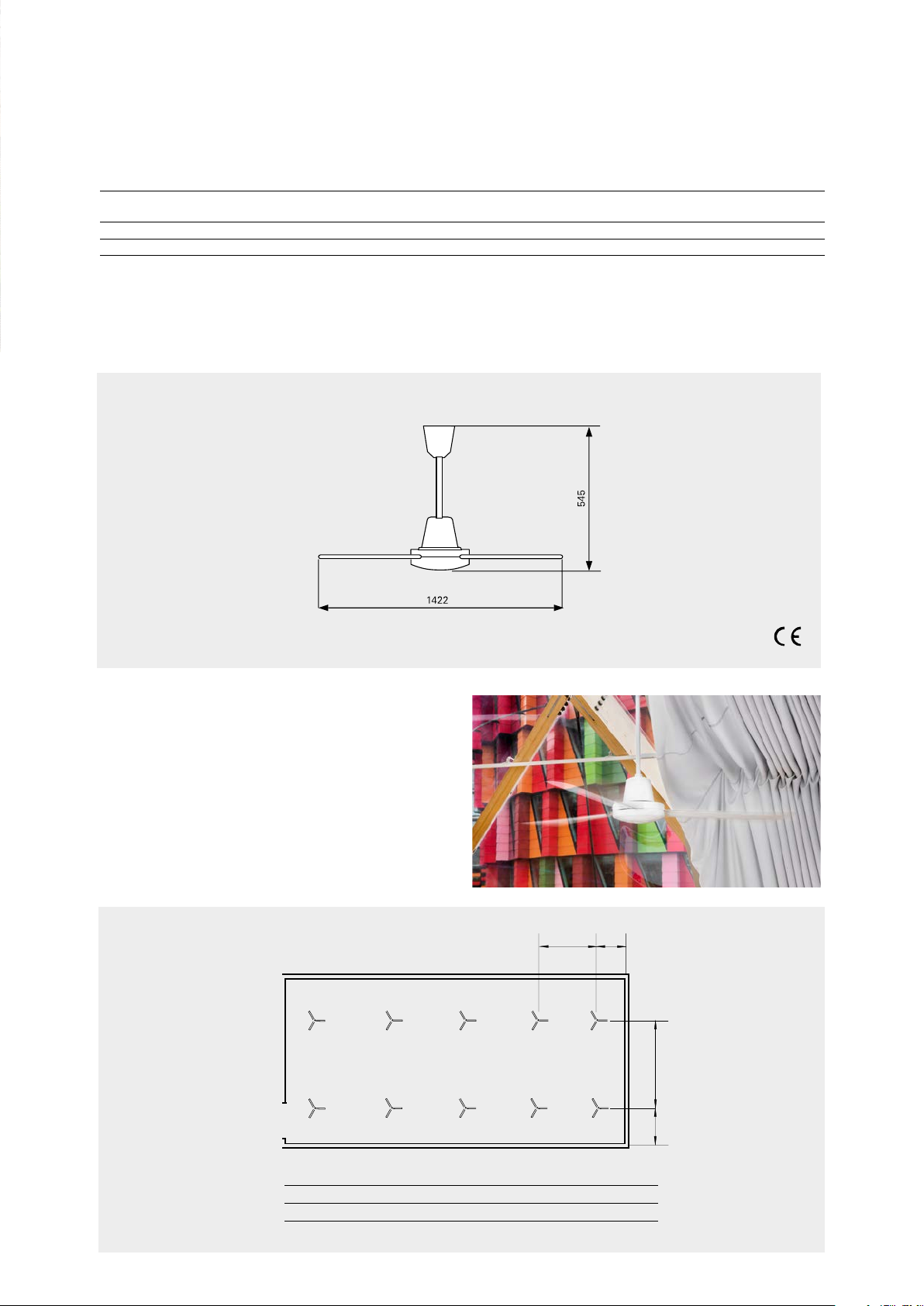
Mounting and connection
The fans are positioned systematically in the room
at equal distances between themselves as detailed in
the table below. This is to give the best temperature
distribution. To adapt the fan to suit each specific room
it should be controlled with a fan speed regulator.
a‘
a‘
Recommended distance between fans
Ceiling height [m]
Distance a [m]
Design and specifications are subject to change without notice.
4 6 8 10 12
5 7 8 9 10

Industrial ceiling fan ICF
Control options
The fan speed on ceiling fans should be controlled to
obtain optimal heat equalization and prevent draughts.
The fan can be reversed for summer operation.
CAR15 and CFR1R have this function, with other
control options a change-over switch is needed. This
• CAR15, automatic fan speed control, reversible
• CFR1R, 5-step control, reversible
• RE1,5 / RE3 / RE5, 5-step control
• PE1 / PE2,5 , variable fan speed control
switch is connected in a series after the control and a
4x1.5 mm² cable must be used.
Accessories
CAR15 CFR1R RE1,5/RE3/RE5 PE1/PE2,5 CFAP CFB
CAR15, automatic fan speed control
Automatic fan speed control, through external sensor, in
accordance with variations in the temperature between
the ceiling and the floor. Built-in switch for reversed
rotation. Max. breaking current: 6,3 A. IP31.
CFR1R, 5-step control
5-step control. Built-in switch for reversed rotation.
Max. breaking current: 0,4 A. IPX0.
RE1,5 / RE3 / RE5, 5-step control
5-step control. Max. breaking current: 1,5 / 3 / 5 A. IP54.
PE1/PE2,5, variable fan speed control
Single-phase manual thyristor for variable speed
adjustment of the fan and on/off regulation. External
mounting (IP54) or recessed mounting (IP44). Max.
breaking current: 1 / 2,5 A.
CFAP200, short downrod
Gives the fan a total height of 395 mm.
CFAP750, long downrod
Gives the fan a total height of 945 mm.
CFB900, fan blades
Gives the fan a diameter of 914 mm.
Complete set of 3 fan blades.
CFB1200, fan blades
Gives the fan a diameter of 1218 mm.
Complete set of 3 fan blades.
Type Description HxWxD
CAR15 Automatic fan speed control, max. breaking current: 6,3 A 210x210x100
CFR1R 5-step control, max. breaking current: 0,4 A 120x120x60
PE1 Variable fan speed control, external mounting (IP54) or recessed mounting (IP44),
max. breaking current: 1 A
PE2,5 Variable fan speed control, external mounting (IP54) or recessed mounting (IP44),
max. breaking current: 2,5 A
RE1,5 5-step control, max. breaking current: 1,5 A 200x105x105
RE3 5-step control, max. breaking current: 3 A 200x105x105
RE5 5-step control, max. breaking current: 5 A 200x105x105
CFAP200 Short downrod, total height 395 mm
CFAP750 Long downrod, total height 945 mm
CFB900 Fan blades, fan diameter 914 mm
CFB1200 Fan blades, fan diameter 1218 mm
[mm]
82x82x65
82x82x65

230V~
Wiring diagrams
Wiring for fan speed control
CAR15,
automatic
fan speed control
L
N
CAR15
~~
LL
L
RF
Industrial ceiling fan ICF
ICF20/55
ICF20/55
M
M
°C
NN
1234
5678
~
~
°C
Black
Black
1
1
Blue
Blue
25
25
Red
Red
ICF20/55
M
~
°C
Black
1
Blue
25
Red
RE1,5/RE3/RE5,
5-step control
CFR1R,
5-step control
RE1,5/3/5
~
CFR1R
NN
NL
230V~
N
L
L
N
230V~
N
N
ICF20/55
~
~
N
~
5
21
1
ICF20/55
1
ICF20/55
1
25
25
25
ICF20/55
1
ICF20/55PE1/2,5
25
1
25
PE,
variable fan speed control
Relay connection
(L)
L
N
230V~
Design and specifications are subject to change without notice.
 Loading...