

Page 1
INFRAGLAS
IHG12/15/22 IP65
MONTAGE- UND GEBRAUCHSANWEISUNG
INSTRUCTIONS FOR USE
MODE D’EMPLOI
ISTRUZIONE PER L’USO
INSTRUCCIONES DE MONTAJE Y USO
MONTAGE- OG BRUGSANVISNING
MONTAGE- OCH BRUKSANVISNING
MONTERINGS- OG BRUKSANVISNING
ASENNUS- JA KÄYTTÖOHJE
Irrtum und technische Änderungen vorbehalten ・ Subject to errors and technical changes ・ Sous reserve d‘erreurs et de
modifications techniques ・Excepto erro ou alteracao tecnica ・Salvo error o modificacion tecnica ・Fejl og tekniske
ændringer forbeholdt ・Fel och tekniska ändringar reserverade ・Feil og tekniske endringer reservert ・Virheet ja tekniset
muutokset on varattu!
Main office: Frico AB, Industrivägen 41, SE-433 61 Sävedalen Sweden
Tel: +46 31 336 86 00 - mailbox@frico.se - www.frico.net
For latest updated information and information about your local contact: www.frico.net
Page 2

EN
9
ASSEMBLY AND OPERATING INSTRUCTIONS
Dear Customer,
please read the following information carefully before using
t
he appliance for the first time for your own safety and to
ensure correct use.
DESIGNATED USE:
Outdoor areas.
SAFETY INFORMATION:
• During use of this appliance, it is necessary to observe
some precautions. Improper operation with disregard of
precautions may result in infliction of harm to health of the
user and other people, as well as in infliction of damage to
their property.
• Use this appliance only as described in this manual. Any
ot
her use is not recommended by the manufacturer and
may cause fire, electric shock or injury.
• Do not use appliance or any part of the appliance out of
the intended use to avoid risk.
• The manufacturer is not responsible for any damage that
could happen from improper use.
• The manufacturer emphasizes that this appliance should
be
used in a responsible manner and that all procedures,
warnings, and safety instructions contained in this booklet
be followed strictly.
• Use only the voltage specified on the rating plate of this
appliance.
• Remove transit protection before use.
• Keep packaging materials out of reach of children.
• This appliance must be handled with care and avoid
vibration or hitting.
• Do not apply any pressure on the glass surface.
• In particularly, do not use the appliance in dusty areas or
ere explosives are stored.
wh
• Do not use the appliance in a building site, green house,
ba
rn or in animal stables.
• Do not use this appliance in the place of animal
agating and rising.
prop
• Do not use the appliance as a sauna heater.
• This appliance is NOT intended to be installed in
wa
rdrobes.
• Do not use this appliance on a wet surface, or where it
c
an fall or be pushed into water.
• Do not reach for an appliance that has fallen into water.
ch off at supply and unplug immediately.
Swit
• Install and operate this appliance in stri
position on the ceiling or ceiling structural surface. The
thermal resistance of the ceiling coating and ceiling
material should be at least 80 °C.
• WARNING: Check for damage to the appliance
re
gularly. The heater must not be used if the black
radiant panel or any other part of the heater is
damaged.
• Only connect the appliance to a properly installed socketoutlet with earthing contact. Possibly a slow-blow C-fuse
is necessary if you experience problems by switching on to
overloaded fuses.
• Only connect the appliance to a.c. mains as specified on
he rating plate.
t
• Never touch live pa
rts! Danger to life!
ctly horizontal
• Never operate the appliance with wet hands! Danger to
life!
• Do not store or use any flammable materials or sprays in
he vicinity of the appliance when the appliance is in use.
t
Fire hazard!
• Do not use the appliance in flammable atmospheres (e.g.
in the vicinity of combustible gases or spray cans)!
Explosion and fire hazard!
portant! Do not insert any foreign objects into the
• Im
appliance openings! Risk of injury (electric shock) and
damage to the appliance!
• Attention!
• A
ttention! The unit complete becomes very hot when
the appliance is in use! Place the appliance so that it
cannot be touched by accident. Risk of burns!
• No objects whatsoever suc
should be fastened to the radiant heater. Ri
ver attempt to adjust the pivoting angle when the
• Ne
device is in operation! Risk of burns!
Allow the appliance to cool down before adjusting the
bra
cket
• The appliance is not intended for use by young children
infirm persons without supervision! Young children
or
should be supervised to ensure that they do not play with
the appliance!
• The socket-outlet must be accessible at all times to
enable the mains plug to be disconnected as quickly as
possible!
• These instructions for use belong to the appliance and
ust be kept in a safe place. When changing owners, these
m
instructions must be surrendered to the new owner!
• The appliance must be allowed to cool
carried and stored!
LOCATION:
• If the radiant heater is equipped with or without a frame
for ceiling mounting it must be secured 2.1-2.3 meter
above the ground. The installation height for the 1.5kW
version is at least 1.8 m above the ground.
• If the radiant heater is equipped with or without a frame
for wall mounting it must be secured 2.1-2.3 meter above
the ground. The installation height for the 1.5kW version is
at least 1.8 m above the ground.
• The device may only be commissioned if it has been
mounted level.
• The distance between the h
objects and other buildings must be a
• Since the device emits radiant heat, make sure that no
items, such as furniture, are located between the device
and the persons or objects to be warmed!
POWER CORD:
• The use of an extension cord with this appliance is not
recommended.
• The power cord must not come into contact with
eated parts of the device!
h
• Never remove the plug from the socket by pulling on
he cord! Never move the device by pulling on the cord or
t
carry the device by the cord!
Do not look longer time into the light!
h as garlands and streamers
sk of fire!
down before being
eater and combustible
t least 100 cm.
Page 3
EN
10
• Do not wind the cord around the device! Do not
operate the device with the cord wound up!
• Do not clamp the cord, or pull it over sharp edges!
• Do not run cord under carpeting, throw rugs or runners
etc. Arrange cord away from areas where it is likely to be
tripped over.
•Never use the appliance if the appliance or cord is
damaged. Risk of injury!
INSTALLATION:
• The device may only be installed and connected by
qualified professionals. The installation must be
isolated prior to commencing any electrical work!
Risk of fire!
• Sufficient air exchange for heat dissipation must
be ensured in the cavity above the radiant heater.
• Only commission the device after it has been fully
installed.
• This heater comes with a pair of stainless steel adjustable
angle mounting brackets. The adjustable angle enables the
heater to be installed on vertical, horizontal and inclined
surfaces.
WARNING:
Slight crackles may be heard during the heating or cooling
period. This is normal operational noise.
NOTE:
After switching on the appliance for the first time and
following extended periods on non-use, the appliance
may expel a slight odor for a short time. It will not affect
the use of the heater.
To exclude unpleasant burnt odor, it is recommended
to keep the heater clean preventing accumulation of
dust on it
The distance between the heater and the remote cont
rol should be less than 3 metre, and the remote contr
ol must be directly point to the receiver on the front p
anel during the operation.
• All repairs must be referred to authorised personnel!
Therefore, you should contact your specialized dealer or
the customer service.
• Important! Any tampering with the appliance will
invalidate the warranty.
• Repairs carried out improperly and by unqualified persons
may have serious consequences for the user!
TECHNICAL DATA:
• Connection/fuse: 230-240V~50Hz with 10 Amp C (= slowblowing fuse) (IHGB/W12, IHGB/W15), with 16 Amp C (=
slow-blowing fuse) (IHGB/W22)
• Output: 1200 Watt, 1500 Watt and 2200 Watt
• Infrared tube: 1,2 kW= IHGB/W12, 1,5 kW= IHGB/W15,
2,2 kW= IHGB/W22,
• Guaranteed service life: up to 5000 hours with average
use
• Type of protection: IP65
• Weight IHGB/W12SR model: 3,6 kg
• Weight IHGB/W15S/R models: 5,1/5,2 kg
• Weight IHGB/W22S/R models: 5,1/5,2 kg
• Casing: Corrosion-resistance anodized aluminium
• Front: SCHOTT NEXTREMA® ceramic glass
• Cable: 1,80m 3-wire 1,5 mm², Schuko plug
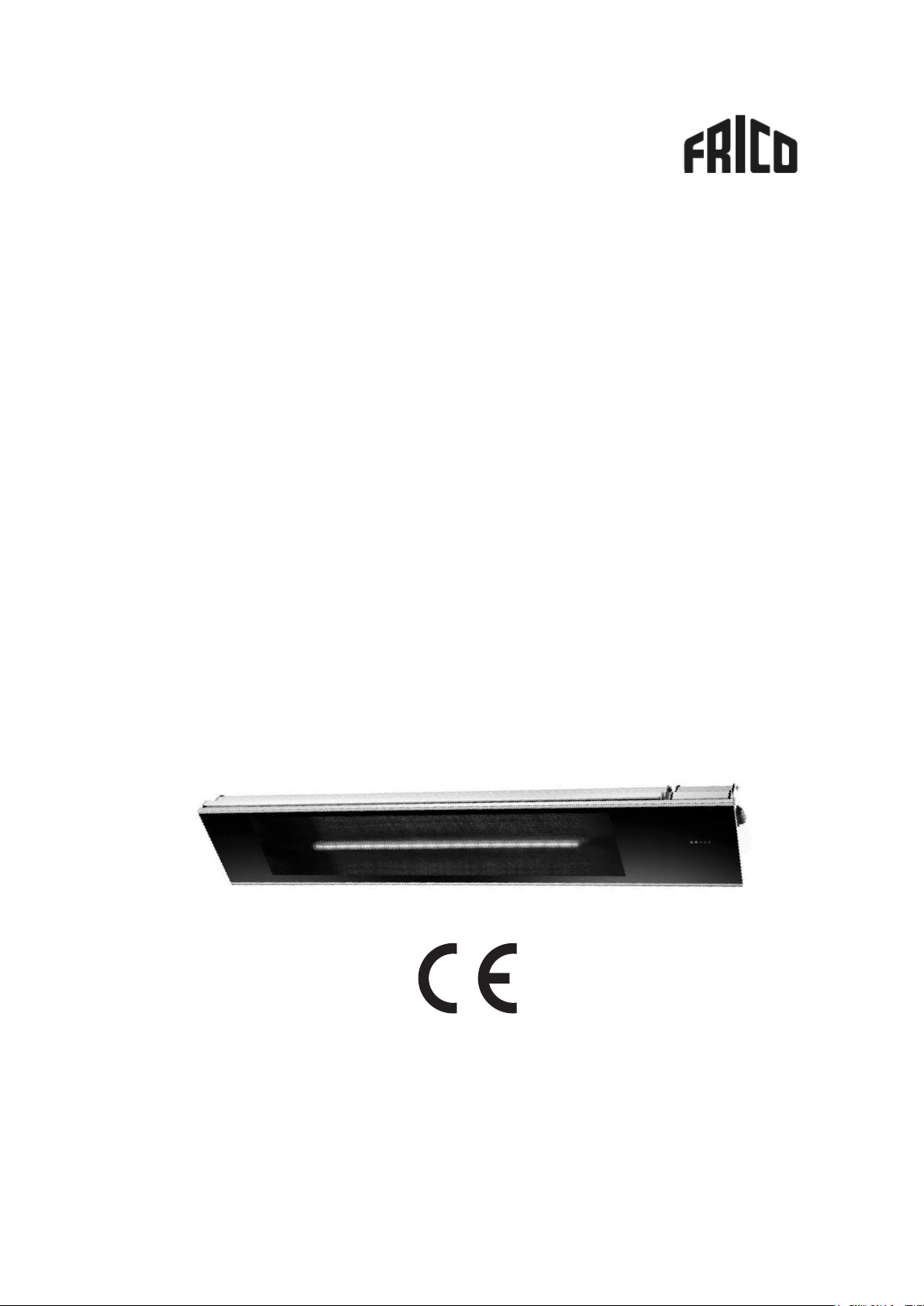
OPERATING INSTRUCTION FOR IHGB/W12SR MODELS:
3
2
4
1. Ceramic glass panel
2. Power cords and plug
3. Brackets for wall or ceiling mounting
4. Remote contro ON/OFF
CLEANING:
• First, disconnect the equipment from the power supply
system!
• After the appliance has cooled down, wipe off dust with a
damp soft rag in cold condition
• During operation, it is necessary to periodically (once a
year) check the electric cable contacts and terminal
connectors for good tightening.
• Do not use any abrasive or caustic cleaning agents!
• Never immerse the appliance in water! Danger to life!
AFTER-SALES SERVICE:
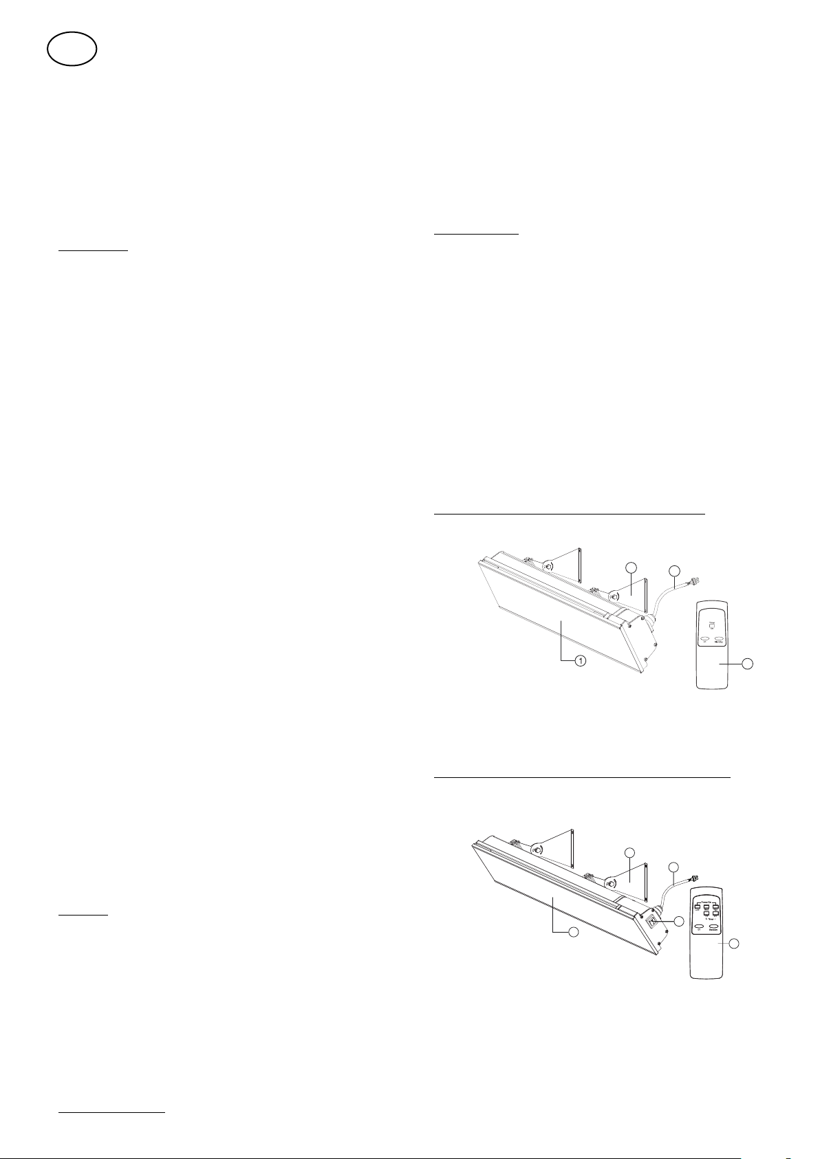
OPERATING INSTRUCTION FOR IHGB/W15/22S/R MODELS:
4
3
1
2
1. Ceramic glass panel
2. ON/OFF main power switch
3. Power cords and plug
4. Brackets for wall or ceiling mounting
5. Remote control (IHGB/W15/22SR)
5
Page 4

IHGB12SR,
IHGW12SR
IHGB15S/R
IHGW15S/R
IHGB22S/R,
IHGW22S/R
Voltage
230-240V~50Hz
230-240V~50Hz
230-240V~50Hz
Power
1200 W
1500 W
2200 W
Installation
Wall, Ceiling, flush mounted
Wall, Ceiling, flush
mounted
Wall mounting only
Wall Mounting Height
1,8 – 2,5 m 1,8 – 2,5 m 1,8 – 2,5 m
Ceiling Mounting Height
Electric Protection Class
I I I
Water Splash Proof Rate
IP65
IP65
IP65
Length of Cable
1,8 m
1,8 m
1,8 m
Dimensions L*W*H
585 x 170 x 80 mm
without bracket
900 x 170 x 80 mm
without bracket
900 x 170 x 80 mm
without bracket
Power on the unit
Standby mode
Set the time function
Plug in the device, the device
will sound 1 beep, the device is
in standby mode, the heating
status lamp is flashing.
Press the button
“standby” on the
remote control, the
device will sound 1
beep and revert to
Standby mode, the
Stand-by lamp is
flashing.
Press the Timer
control button ”1hr”,
to activate 1-hour
delay-off timer
function. The heating
status lamp will turn
to green.
Press the button “ON” on the
remote control, the device
starts to heat, and the heating
status lamp will turn in red.
Power off the unit:
Unplug the device from
the socket or press the
switch or the circuit
break to power off the
device
The device will be
switched off after 1
hour, and revert to
standby mode.
CAUTION: There is a built in safety feature that will automatically trigger the heater to go into
standby mode after eight hours of continuous operation. When this happens, the stand-by
lamp will be flashing.
11
Heating status lamp
2 – 3 m 2 – 3 m
EN
INSTRUCTION FOR IHGB/W12SR
Page 5

Power on the unit
Standby mode
Set the time function
Plug in the device, and
then press the switch to
the position I. Point the
remote control directly to
the receiver, press the
button “ON” on the
remote control, the
device will sound 1 beep
and starts to heat in high
power mode (100% the
rated power).
Press the button
“standby” on the
remote control, the
device will sound 1
beep and revert to
Standby mode, the
Stand-by lamp is
flashing.
Press either, or both
of the Timer control
buttons (picture 11),
to activate the delayoff timer function. (1,
2 or 3-hour options).
1 Hour Timer:
Point the remote
control directly to the
receiver and press the
button of “1hr”. The
1st timer status lamp
will turn to green, the
device will be
switched off after 1
hour, and revert to
standby mode.
All three heating status
lamps will turn in red. The
unit is in heating mode
now.
Power off the unit:
Press the switch to
the position O
2 Hour Timer:
Point the remote
control directly to the
receiver and press the
button of “2hr”, the
2nd lamp of timer will
turn to green color,
the device will switch
off after 2 hours, and
the device will be in
standby mode, and
revert to Standby.
3 Hour Timer:
Point the remote
control directly to the
receiver and press the
button of “1hr” and
“2hr”, both timer
status lamps will turn
to green color, the
device will switch off
after 3 hours, and
revert to Standby
mode.
EN
12
On/off
Switch
INSTRUCTION FOR ALL OTHER DIMMABLE MODELS
1500/2200:
Stand-b y
Heat Function Display
Timer Function Display
Page 6

INSTALLATION DETAILS:
13
Horizontal ceiling mount
Inclined ceiling mount
Angled horizontal ceiling mount
• The ideal mounting position is directly above the area to
be heated with a longitudinal orientation and facing
vertically downwards.
WARNING:
The heater must never be installed in the upwards or
inwards facing position, the heating surface must always be
positioned to direct the heat in a downwards or outwards
direction.
Correct Installation
CEILING CEILING CEILING
WALL
Incorrect Installation
WALL
WALL
EN
Fans, lights and
sprinkler fittings
MUST NOT
be below heater
1000 mm minimum to surface
(ie table tops, etc)
2100 min. from floor
3000 mm max. from floor
(recommended)
Same on both
WARNING:
Mounting of the infrared heater and its connection to
the electric mains should be carried out only by
qualified specialists according to the Electrical
Installation Regulations and Power System Safety
Standards.
INSTALLATION PROCESS:
1. Open the factory package and carefully take the heater
out.
2. Take out the packing paper sheet from the end of heater.
3. Take out one pair of mounting Brackets. These adjustable
brackets allow direct ceiling or wall mount, and come with
preset angle options of parallel, 15°, 30°, 45° and height
165mm.
ends
• Find below the minimum clearances when mounting the
heater parallel with a ceiling. (Unit in mm)
Fans, lights and
sprinkler fittings
MUST NOT
be below heater
1000 mm minimum to surface
(ie table tops, etc)
2100 min. from floor
3000 mm max. from floor
(recommended)
Same on both
• Find below the minimum clearances when mounting the
ends
heater at an angle to the ceiling. (Unit in mm)
Fans, lights and
sprinkler fittings
MUST NOT
be below heater
1000 mm minimum to surface
(ie table tops, etc)
2100 min. from floor
3000 mm max. from floor
(recommended)
Same on both
ends
• Find below the right wall mounting position. (Unit in mm)
mm
15
165mm
4. The correct installation process, as per the diagram
above, select the heater location on the ceiling by locating
the stud or structural beams to ensure secure fastening of
the heater, whilst observing the minimum clearances from
the floor and other objections.
5. Install two brackets on the ceiling or wall with the
following minimum recommended bracket distance “B”.
6. Set the adjustable angle mounting brackets to desired
angle and fasten brackets by spanner.
Correct Installation
CEILING
WALL
Page 7

Model No
“B” (mm)
MINIMUM DISTANCE
1200W
300±20
1500W
500 ±50
2200W
500 ±50
EN
14
• For ceiling mounted installation, the available mount
angles are restricted to 0°, 15° and 30° only.
• For wall mounted installation, the available mount angles
are restricted to 15°, 30° and 45° only.
Ceiling
circuit breaker with rated current not less than 16A..
• The heater must not be located immediately below a
power point. Power point should not be located at the back
of the heater. The power point needs to be located outside
the physical footprint of the heater to minimize heat buildup behind the heater.
• If the heater is to be mounted on an incline (eg. Vaulted
ceiling), ensure the power point located at that lowest point
of the heater.
Correct Installation
Incorrect Installation
WIRING SCHEMATIC DIAGRAM:
Wall
7. Hang the heater on the brackets and firmly secure in
place with the mounting bracket locking plates by
tightening bolts.
NOTE:
Depending on material and design of ceiling structural
elements, the heater must be secured with the correct
fasteners. The weight of the heater is up to 5.3Kg, the
installation location must be able to hold 5 times the
weight of the heater.
CONNECTION TO ELECTRIC MAINS:
• The heater is designed for connection to the single-phase
230-240V~ 50Hz electric mains equipped with an earth
wire.
• Before connection, make sure that specifications of the
electric mains at the connection point meet the singlephase 230-240V~ 50Hz voltage.
• Regarding the model IHGB/W12SR
In case of direct connection to the supply line, a bipolar
switch or a bipolar circuit breaker with contact opening
distance of at least 3mm must be fitted upstream from the
supply line. Contact an authorized service technician if you
are unsure if you have a switch or a circuit breaker installed
on the premises.
• The electric mains should be equipped with an automatic
circuit breaker with C curve type (slow blow fuse) and with
rated current not less than 10A (model 1500W) or 16A
(model 2200W). Contact an authorized service technician if
you are unsure if you have a circuit breaker installed on the
premises
• The electric mains should be equipped with an automatic
IHGB/W12SR:
IHGB/W15S, IHGB/W22S:
Switch
IN-L
IN-N
OUT-L
Heating Element
1200W
Heating Element
1500W
2200W
Page 8

IHGB/W15SR, IHGB/W22SR:
SYMPTOM
CAUSE
Will not heat / No operation indicator
Check that power is connected and switched on.
Heater smells when first used.
This is caused by oil or dust left over from the manufacturing process and will
stop after a short time.
Faint smell for short periods after turning on
the heater.
This is normal and should stop after a short time.
Heater smells when turned on after periods
of no use.
Build-up of debris and dust on the heater, Switch the heater off and allow it
to cool down and then clean.
Clinking noises when heater is turned on and
after being turned off.
This is expansion and contraction noises of the heaters metal components
and is normal.
Poor heating performance.
Exposure to extreme ambient conditions such as high winds / excessively
cold temperatures can lower the heating performance of an outdoor
installation.
Unit is not installed in correct position, possibly too high or heater is too
small for recommended area.
There is a burning smell and or strange
sounds (other than normal expansion and
contraction noises) coming from the unit.
Turn off the heater, and contact the authorized service or seller.
When associated circuit breaker (safety,
ground) is thrown or a fuse is blown.
Turn off the heater and contact the authorized service or seller.
Poor heating performance.
Incorrectly sized installation. Contact the authorized service or seller.
Faulty heater element turns off the heater. Contact the authorized service or
seller.
Will not heat / No operation indicator.
Check that power is connected and switched on, if still faulty, turn off the
heater. Contact the authorized service or seller.
15
EN
Switch
IN-L
IN-N
OUT-L
Heating Element
1500W
2200W
TROUBLESHOOTING
• Possible malfunctions are given in Table below.
CORRECT DISPOSAL OF THIS PRODUCT:
This marking indicates that this product should not be
disposed with other household
wastes throughout the EU. To prevent possible harm to
the environment or human
health from uncontrolled waste disposal, recycle it
responsibly to promote the sustainable
reuse of material resources. To return your used device,
please use the return and collection
systems or contact the retailer where the product was
purchased. They can take this product
for environmental safe recycling.
 Loading...