

IHC
.... 9
SE
.... 22
RU
....16
FR
.... 11
NO
.... 6
GB
.... 13
DE
.... 19
ES
IHC
2
500/676
169
160
0,9 m
77
147
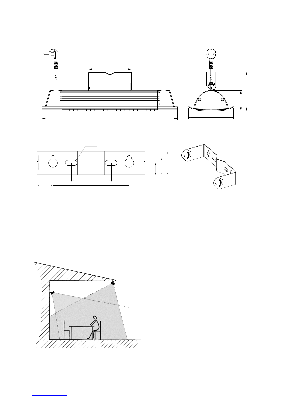
Positioning
Fig. 2: The heaters should heat from at least two
directions for even heating
46,5
60
11 524
ø8
17,5
25,5
35
Fig. 1: Wall bracket
Dimensions
IHC
3
1
33
4
5
2
1
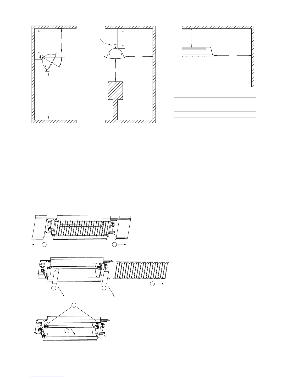
Fig. 4: Replacing the carbon lamp
Fig. 3: Minimum mounting distance
200
180
min 30°
B
300
A
160
IHE, ceiling
bracket (1)
500
Minimum
distance
[mm]
Flammable material (2) A 1000
Floor (3) B 1800
(1)
SE: IHE, takfäste
GB: IHE, ceiling bracket
NO: IHE, takfeste
FR: IHE, console de montage au plafond
RU: IHE, скоба потолочного крепления
DE: IHE, Decken-halterung
PL: IHE, uchwyt sufitowy
ES: IHE, soporte de techo
NL: IHE, plafond-beugel
IT: IHE, staffa a soffitto
(2)
SE: Brännbart material
GB: Flammable material
NO: Brennbart materiale
FR: Matériau inflammable
RU: Легковоспламеняемые материалы
DE: Entflammbares Material
PL: Materiał łatwopalny
ES: Material inflamable
NL: Brandbaar materiaal
IT Materiali infiammabili
(3)
SE: Golv
GB: Floor
NO: Gulv
FR: Sol
RU: Пола
DE: Boden
PL: Podłoga
ES: Suelo
NL: Vloer
IT: Pavimento
IHC
4
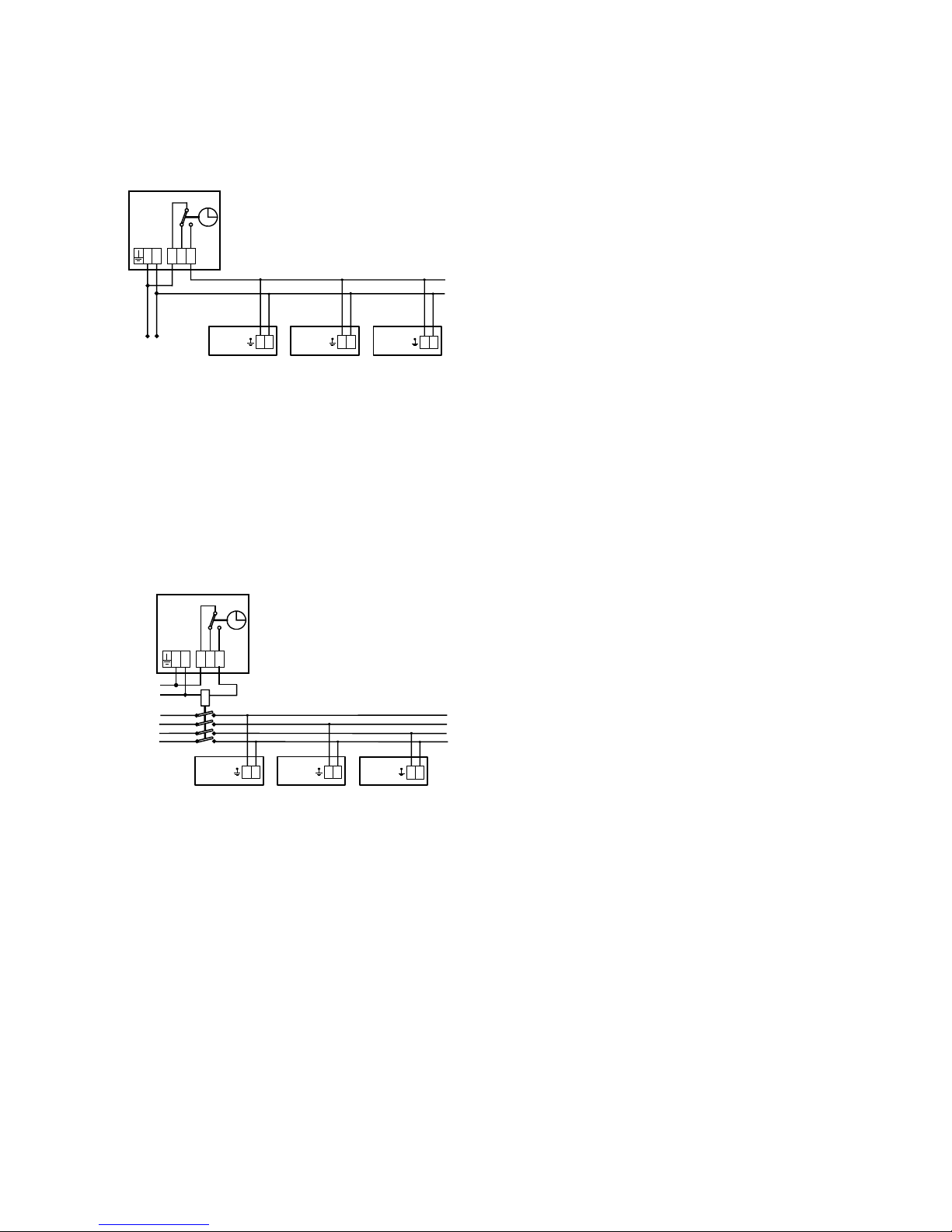
Wiring diagrams IHC
Timer control
Timer control with contactor
N
IH/IHC
123
CBT
LN
L
N
IH/IHC
L
N
IH/IHC
L
230V~
Max load 3500W
N
IH/IHC
123
CBT
230V~
LN
L
N
IH/IHC
L
N
IH/IHC
L
L1
L2
L3
N
L
N
400V3~

IHC
5
(1)
SE: Effekt
GB: Output
NO: Effekt
FR: Puissance
RU: Выходная мощность
DE: Abgabe
PL: Moc
FI: Teho
ES: Potencia
(2)
SE: Spänning
GB: Voltage
NO: Spenning
FR: Tension
RU: Напряжение
DE: Spannung
PL: Napięcie
FI: Jännite
ES: Tensión
(3)
SE: Ström
GB: Amperage
NO: Strøm
FR: Intensité
RU: Сила тока
DE: Strom
PL: Natężenie prądu
FI: Virranvoimakkuus
ES: Intensidad
(4)
SE: Maximal yttemperatur
GB: Max. surface temperature
NO: Maksimal overflatetemp.
FR: Température de surface
RU: Max. темпер. греющ. поверх.
DE: Max. Oberflächentemperatur
PL: Max. temperatura powierzchni grzewczej
FI: Maks. pintalämpötila
ES: Máxima temperatura de superficie
(5)
SE: Längd
GB: Length
NO: Lengde
FR: Longueur
RU: Длина
DE: Länge
PL: Długosc
FI: Pituus
ES: Longitud
(6)
SE: Vikt
GB: Weight
NO: Vekt
FR: Poids
RU: Вес
DE: Gewicht
PL: Waga
FI: Paino
ES: Peso
Type E-nr
(SE)
EL-nr
(NO)
Heat
output (1)
[W]
Voltage (2)
[V]
Amperage (3)
[A]
Max. filament
temperature (4)
[°C]
Length (5)
[mm]
Weight (6)
[kg]
IHC12 85 700 07 54 911 05 1150 230V~ 5,0 1200 500 1,9
IHC18 85 700 08 54 911 06 1750 230V~ 7,6 1200 676 2,5
Protection class IHC: (IPX4), splash-proof design.
CE compliant.
Technical specifications | Carbon infrared heater IHC with wide heat distribution, installation height 2 - 3 m 3

IHC
6
GB
General Instructions
Read these instructions carefully before
installation and use. Keep this manual for
future reference.
The product may only be used as set out in
the assembly and operating instructions. The
guarantee is only valid if the product is used
in the manner intended and in accordance
with the instructions.
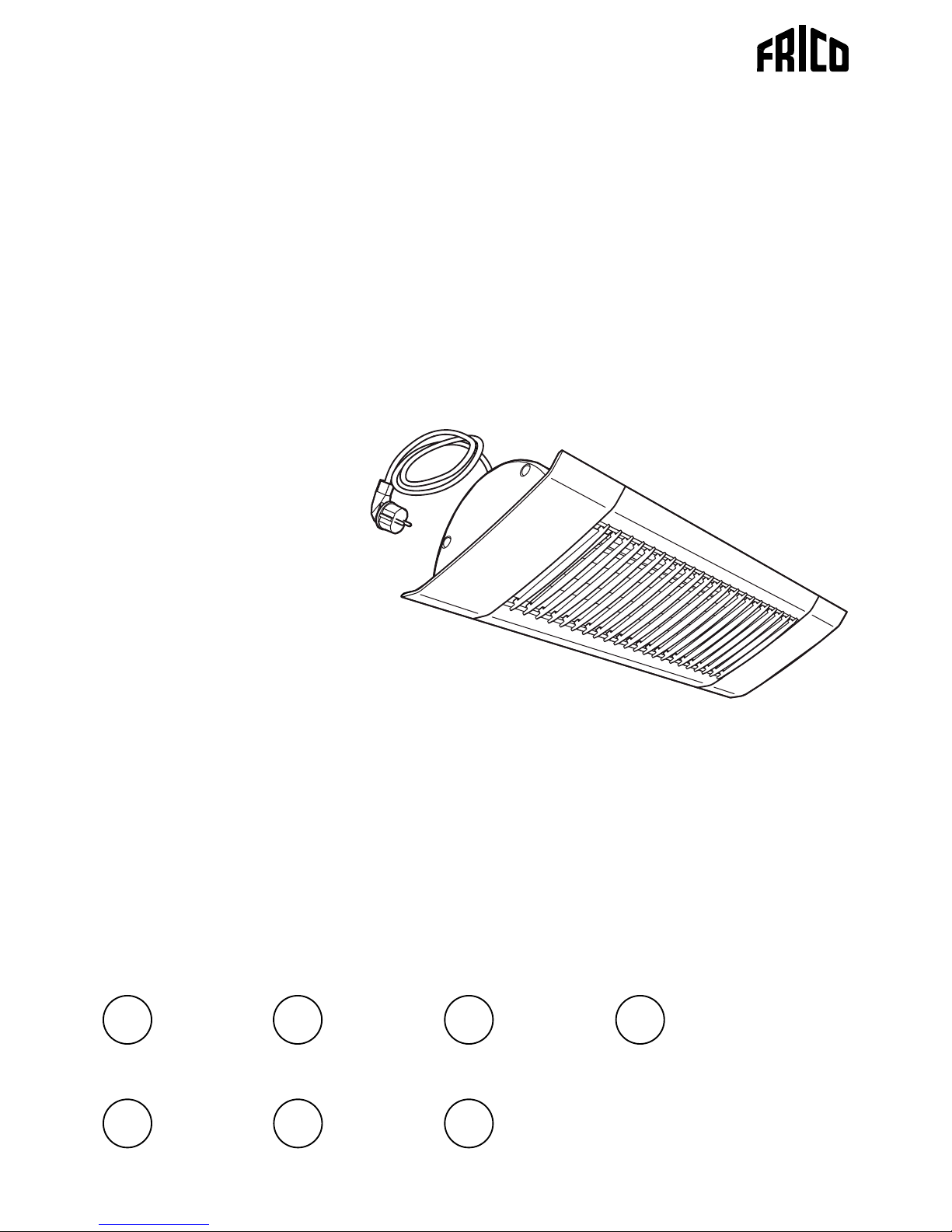
Application
Carbon infrared heater IHC produces a gentle
and direct heat which together with the soft
glow, is ideal for indoors and conservatories
as well as for outdoor restaurants where
design is important. IHC can also be used
as local heating. IHC has a heat distribution
best suited for close and slightly higher
installations.
Protection class: IPX4
Positioning
The heaters must be placed so that they
enclose the area to be heated, see fig. 2. The
normal assembly height is 2–3 metres above
the ground/floor. A rule of thumb for infrared
halogen is that 600–800 W/m² increases the
experienced temperature by about 10 °C. The
output demand can be reduced if the area to
be heated is protected. If the area only has a
roof, at least 800 W/m² should be installed.
600 W/m² is sufficient if the area has three
walls. For enclosed areas, the output demand
must be calculated. Optimum comfort is
achieved if the heat is distributed from at
least two directions.
We recommend an installation height of 2 - 3
m for IHC.
Mounting
IH/IHC is mounted on the wall using the
bracket, see fig 1. The heater can also be
mounted on e.g. a parasol or a post, a suitable
U-bolt (not included) is used for this together
with the supplied console. IH/IHC can also be
mounted in the ceiling. For other mounting
alternatives, see accessories.
The heater must be mounted in a horizontal
position in order to keep the lamp horizontal.
The heater can be directed straight out from
the wall or angled up to 45°. For minimum
measurements, see fig. 3.
1. Secure the bracket on the wall, see fig. 1.
Note that the wall bracket must not only be
fitted with the screws in the keyhole slots.
2. Remove the screws fixed to the unit's
attachment on delivery.
3. Hook the attachment on the bracket.
4. Lock in position with the screws.
Note that the unit must not be placed directly
under the permanent wall socket.
Electrical installation
IHC is equipped with a 0.9 metre cord with
plug for connection to an earthed outlet
socket.
The connection cord must not rest against
the unit as the surface becomes hot or can
be hit by thermal radiation. Contact an
electrician if the cord needs to be changed.
Note that due to the high temperatures in the
heater, a cord of the type H05 RN-F 3G1 mm
2
or the like should be used.
In the event of uncertainty contact an
electrician.
Start up (E)
When the unit is used for the first time or
after a long period of disuse, smoke or odour
may result from dust or dirt that has collected
on the element. This is completely normal
and disappears after a short time.
Replacing the carbon lamp
The heat lamp in IHC is of the highest quality
and unless it is subjected to mechanical
strains in the form of vibrations and impact
it will last for a long time. The service life is
Assembly and operating instructions

IHC
7
GB
dependent on the ambient temperature and
how the heater is installed. The lamp must
be replaced by an installer or other skilled
person.
- Disconnect the power supply.
- Wait until the unit is cold.
1. Remove the covers at both ends (four
screws).
2. Pull the grille to one side.
3. Remove both reflector ends (two screws).
4. Loosen the connections on the terminal
block.
5. Pull the lamp out of the lamp holders.
- Check that the replacement lamp has the
correct output and voltage.
- Fit the new lamp. Note do not touch the
lamp with your fingers, wear gloves or the
like.
- The protective tube must be refitted to the
cables, so that the cables are not damaged
when the grille is fitted.
- Reassemble the unit again.
See fig. 4.
Maintenance
When the unit is used for the first time or
after a long period of disuse, smoke or odour
may result from dust or dirt that has collected
on the element. This is completely normal
and disappears after a short time.
The power supply to the unit must be
disconnected during all service, repair and
maintenance work.
The unit has no moving parts so the
maintenance requirement is small, but it
must be kept clean and free from dust and
dirt. If the reflector is not clean the thermal
radiation from the unit will decrease and the
heater will become hotter. A large amount of
dirt can cause overheating.
The surface of the reflector is sensitive and
must be cleaned with care. If the reflector
is dirty it must be cleaned or replaced by a
specialist.
Residual current circuit breaker (E)
When the installation is protected by means
of a residual current circuit breaker, which
trips when the appliance is connected,
this may be due to moisture in the heating
element. When an appliance containing a
heater element has not been used for a long
period or stored in a damp environment,
moisture can enter the element.
This should not be seen as a fault, but is
simply rectified by connecting the appliance
to the mains supply via a socket without a
safety cut-out, so that the moisture can be
eliminated from the element. The drying
time can vary from a few hours to a few days.
As a preventive measure, the unit should
occasionally be run for a short time when it is
not being used for extended periods of time.

IHC
8
GB
Safety
• For all installations of electrically heated
products should a residual current circuit
breaker 300 mA for fire protection be used.
• During operation the surfaces of the unit
are hot!
• The unit must not be fully or partially
covered with inflammable materials, as
overheating can result in a fire risk!
• This product is not designed to be used by
children or persons with reduced physical
or mental ability or a lack of experience
and knowledge, unless instruction
regarding the product's use has been
given by a person with responsibility for
their safety or that this person supervises
operation. Children must be kept under
supervision to ensure they do not play with
the product.
• The heater is equipped with a protective
grille to prevent contact or to prevent
large objects from touching the hot lamp.
The unit must not be used without this
protective grille.
• Ensure that there are no inflammable
materials gathered on or close to the
heater.
• The free space to the inflammable material
in the direction of radiation must be at
least 1 meter.
• Do not place the heater directly under the
electrical socket.
• The cable and plug must not be placed
inside the hot radiant area.


Art no: 111741, 20140428 SÄ/CH
Main offi ce
Frico AB Tel: +46 31 336 86 00
Box 102 Fax: +46 31 26 28 25
SE-433 22 Partille mailbox@frico.se
Sweden www.frico.se
For latest updated information and information
about your local contact: www.frico.se
 Loading...