

Frico HP-300, HP-304, HP-305, HP-604, HP-605 Assembly And Operating Instructions Manual
...Page 1
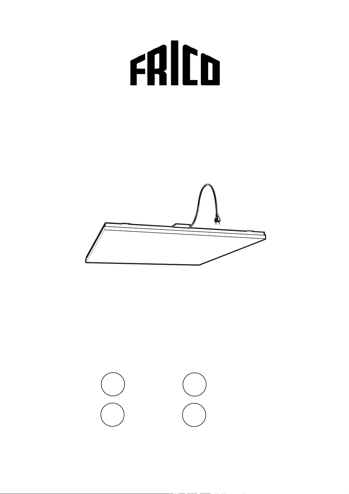
Thermocassette
HP
SE
NO
... 4
... 6
GB
DE
... 8
... 10
Page 2
Thermocassette HP
2
Page 3
Thermocassette HP
3
Page 4
Thermocassette HP
Assembly and operating instructions Thermocassette HP-300/304/305/600/604/605
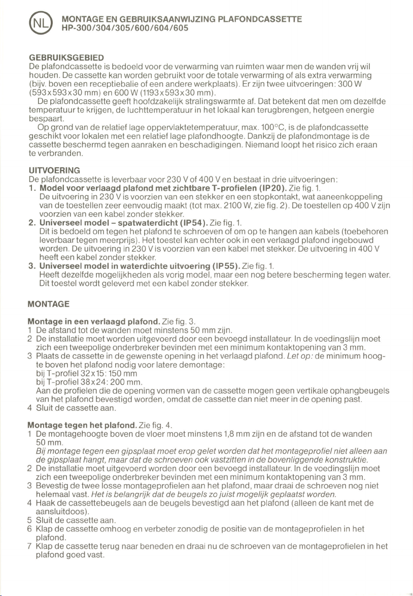
Area of use
The heating panel is intended for the heating of
rooms requiring free walls. The panel can be used
for complete heating, or as an additional heater
(e.g. over a reception desk or other work place.)
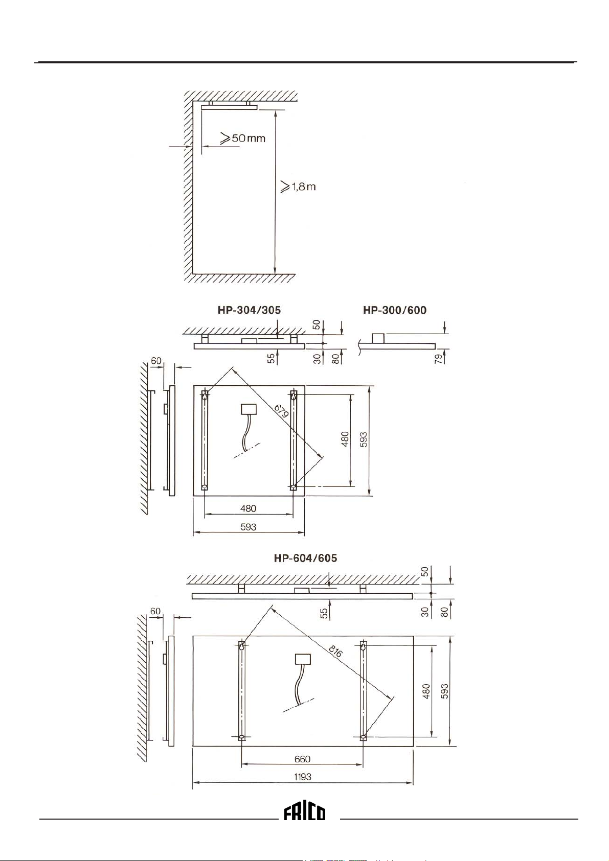
There are two ratings: 300 W(593x593x30 mm)
and 600 W(1193x593x30 mm).
The heating panel provides mainly radiation
heating. This implies that to obtain the same
experienced temperature it is possible to reduce
the air temperature in the room, which saves
energy.
Because of the low surface temperature, max
100°C, the heating panel is suitable for rooms with
relatively low ceiling height. Thanks to the
location, the panel is protected from any physical
contact or damage. There is no risk of being
burned.
Design
The heating panels are available for 230 and 400
V, which are approved by SEMKO in three
versions:
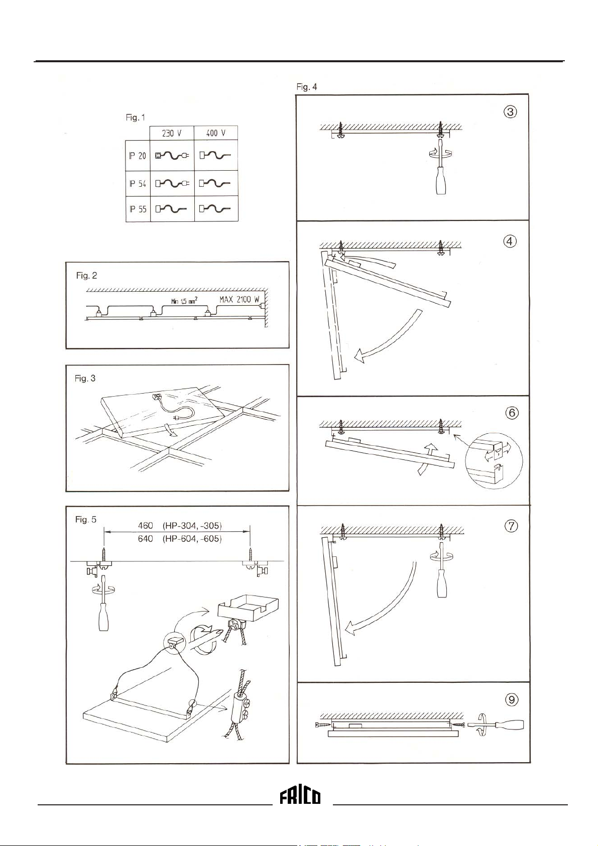
1 . Ceiling model in standard version (IP20).
See fig. 1.
Intended as lay-in panel fpr exposed grid. The
230 V version have cord and socket, which
ensures simple extended connection (max
2100 W from one wall socket. See fig. 2). The
400 V versions are delivered with a cable
without plug.
2 . Universal model in splash-proof design
(IP54). See fig. 1.
Intended for other methods of mounting (can
also be put in exposed grid). Approved for fire
hazard rooms. The 230 V versions have a cord
(without socket). The 400 V versions are
delivered with a cable without plug.
a. Screwed to ceiling with accompanying
mounting brackets.
b. Hanging in wire (with accessory
”Wire mounting kit” 74 701 90).
3 . Universal model in flush-proof design (IP55).
See fig. 1.
Identical with 2, but with better protection
against water. Delivered with cable without
plug.
Mounting
Integrated in ceiling (put in exposed grid).
See fig. 3.
1 . Lateral distance to wall shall be at least
50 mm.
2 . Installation, which is to be preceded by an all-
pole switch, must be carried out by an
authorized electrician (not applicable to
versions with a cord).
3 . Place the cassette in the required ceiling
square. Minimum design height ”H” for
dismounting, T-profile 32x15: 150 mm,
T-profile 38x24: 200 mm.
NOTE! Avoid fixing vertical bars in the T-profile
where a heating panel is to be installed.
The panel fills out the whole square.
4. Connect the panel.
Bracket mounting. See fig. 4.
1. Mounting height above floor shall be at least
1.8 m, and lateral distance to wall at least 50
mm. When mounting in gypsum board, make
sure that the mounting brackets are anchored in
the beam behind. During long-term high
temperatures the strength of the board is
reduced.
2 . Installation, which is to be preceded by an all-
pole switch, must be carried out by an
authorized electrician (not applicable to
versions with a cord).
3 . Measure, drill and screw the two loose brackets
to the ceiling. Do not tighten the screws yet. It is
important that the holes come at right angles,
cross measure.
4 . Hook the panel brackets to the ones on the
ceiling (only the side nearest to the connection
box). Allow panel to hang vertical.
5. Connect the panel.
6 . Swing up the panel, and adjust the lateral
position of the ceiling mounted brackets.
7 . Swing down the panel and tighten the screws in
the ceiling.
8 . Swing up the panel again and hook the panel
bracket ends in the ceiling brackets. NOTE!
Make sure that the brackets do not become
unhooked at the other end.
9 . Secure the panel with a screw (enclosed on
delivery) at each hanging point.
8
Page 5

Thermocassette HP
Wire hung. See fig.5.
1. Mounting height above floor shall be 1.8 m,
and lateral distance to wall at least 50 mm.
2 . Installation, which is to be preceded by an all-
pole switch, must be carried out by an
authorized electrician (not applicable to version
with a cord).
3 . Measure, drill and screw in the wire
attachments envloesed in
”Wire mounting kit” 74 701 90 to the ceiling
4 . Insert one wire end in each screw hole in the
bracket ends on the panel, and fix with a screw
terminal
5 . Hang up the panel bt hanging one wire on the
screw in each wire attachment in the ceiling.
Tighten the screws.
6. Connect the panel.
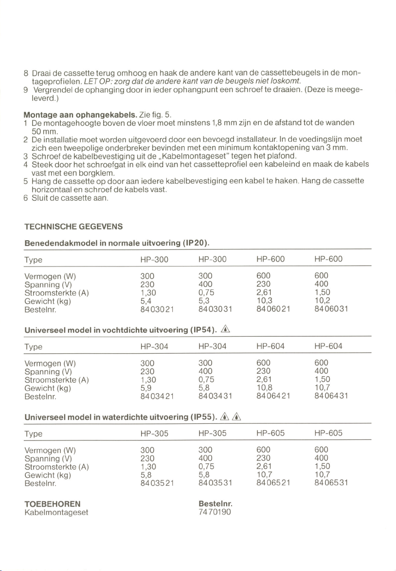
Technical Data
Ceiling model - standard version IP20
Typ HP-300 HP-300 HP-600 HP-600
Power (W) 300 300 600 600
Voltage (V) 23 0 400 230 40 0
Current (A) 1,30 0,75 2,61 1,50
Weight (kg) 5,4 5,3 10,3 10,2
Order nr. 84 030 21 84 030 31 84 060 21 84 060 31
Universal model - waterproof version IP54
Typ HP-304 HP-304 HP-604 HP-604
Power (W) 300 300 600 600
Voltage (V) 23 0 400 230 40 0
Current (A) 1,30 0,75 2,61 1,50
Weight (kg) 5,9 5,8 10,8 10,7
Order nr. 84 034 21 84 034 31 84 064 21 84 064 31
Universal model - waterproof version IP55
Typ HP-305 HP-305 HP-605 HP605
Power (W) 300 300 600 600
Volatage (V) 2 30 400 230 400
Current (A) 1,30 0,75 2,61 1,50
Weight (kg) 5,8 5,8 10,7 10,7
Order nr. 84 035 21 84 035 31 84 065 21 84 065 31
Accessories E- nr. Order nr.
Wire mounting kit 85 744 90 74 701 90
9
Page 6

Page 7

Page 8

Page 9

Page 10
Page 11
Page 12

Thermocassette HP
Tillverkardeklaration/
EU-försäkran om överensstämmelse
Vi
Frico AB
Box 102
S-433 22 Partille
Intygar härmed att följande produkter:
Rumsvärmare: Thermocassette
Typ: HP 300, HP 304, HP 344 och HP 305.
HP 600, HP 604, HP 644 och HP 605.
Uppfyller kraven enligt följande direktiv:
EC Electromagnetic Compatibility (EMC)
Directive 89/336 /EEC & 92/31 EEC
EC Lågspänningsdirektivet(LVD) 73/23/EEC
Och tillverkad enligt följande standarder:
Declaration of Conformity
We
Frico AB
Box 102
S-433 22 Partille
under own responsibility hereby declare that the
following product(s)
Room heaters: Ceiling-cassettes
Type: HP 300, HP 304, HP 344 and HP 305.
HP 600, HP 604, HP 644 and HP 605.
which is(are) covered by this declaration of
conformity comply with the
EC Electromagnetic Compatibility (EMC)
Directive 89/336 /EEC & 92/31 EEC
EC Low Voltage Directive (LVD) 73/23/EEC
EMC: EN 55014: 1993
EN 60555-2/3: 1991
EN 55 104
LVD: CCA HD 251 S3:1982 incl. Am. 1-3
CCA HD 251 S1:1987 incl. Am. 1-4
Partille , 15 December 1995
Mats Careborg
Teknisk Chef
and is(are) manufactured in accordance with the
following stated harmonised standard(s) or other
normative document(s).
EMC: EN 55014: 1993
EN 60555-2/3: 1991
EN 55 104
LVD: CCA HD 251 S3:1982 incl. Am. 1-3
CCA HD 251 S1:1987 incl. Am. 1-4
Partille , 15 December 1995
Mats Careborg
Technical Manager
12
Page 13

Main office
FRICO AB Tel: +46 (0)31 336 86 00
Box 102 Fax: +46 (0)31 26 28 25
S-433 22 Partille e-mail: mailbox@frico.se
SWEDEN http://www.frico.se
France
FRICO FRANCE Tel: +33 (0)4 72 42 99 42
7, rue de la libération Fax: +33 (0)4 72 42 99 49
F-69 270 Fontaines sur Saone e-mail: info@frico.fr
FRANCE
Norway
FRICO AS Tel: +47 (0)23 37 19 00
Postboks 82, Alnabru Fax: +47 (0)23 37 1910
N-0614 Oslo e-mail: mailbox@frico.no
NORWAY http://www.frico.no
For latetest updated information, see: www.frico.se
Russia
FRICO representative office in Russia
1 st Golutvinsky per., 3 Tel: +7 095 238 63 20
Moscow 109180 Fax: +7 095 238 64 20
RUSSIA e-mail: frico@orc.ru
 Loading...