

Page 1
GB
Instruction for products with software version 1.2.
Read this instruction before installation and wiring
i
of the product. This product is BTL listed from
software version 1.2-1-00 (BACnet stack 3.0.4).
Consult documentation in all cases where this symbol
is used, in order to nd out the nature of the potential
hazards and any actions to be taken
INSTRUCTION
FCR-230
FCR230
Room controller for controlling fan-coil units
FCR-230 is a room controller intended for controlling fan-coil heaters/
coolers and thermal actuators or 3-point actuators. Installation is
directly on the wall or on an electrical connection box. The fan can be
set to one of three speeds.
FCR-230 has change-over function and can be used for 2-pipe or
4-pipe systems.
For integration into a system, FCR-230 has communication via
RS485 (Modbus, BACnet or EXOline). The device can be congured
using the application Regio tool (version 1.3-1-05 or later), which can
be downloaded from the Regin web site (www.regin.se).
Technical data
Supply voltage 230 V AC ±10 %, 50/60 Hz
Power consumption < 3 W
Ambient temperature 0...50°C
Ambient humidity Max 90 % RH
Storage temperature -20...+70°C
Built-in temperature sensor NTC type, range 0...50°C
Inputs Refer to connection illustrations and
table below
Outputs Relays for fan control, 230 V AC, 3 A
DO4, DO5 for actuators, Triac, 230 V AC,
max. 300 mA
Communication RS485: Modbus, EXOline (using
automatic detection/switching) or BACnet
Modbus 8 bits, 1 or 2 stop bits. Odd, even
(FI) or no parity
Communication speed 9600, 19200, 38400 bps (EXOline, Modbus
and BACnet) or 76800 bps (BACnet only)
Terminal blocks Lift type for a maximum cable area 2.1 mm
Protection class IP20
Pollution degree 2
Overvoltage category 3
Material casing Polycarbonate, PC
Dimensions 102 x 120 x 29 mm
2
Installation
Place the controller in a location that has a temperature representative for
the room. A suitable location is approx. 1.6 m above oor level in a place
with unobstructed air circulation.
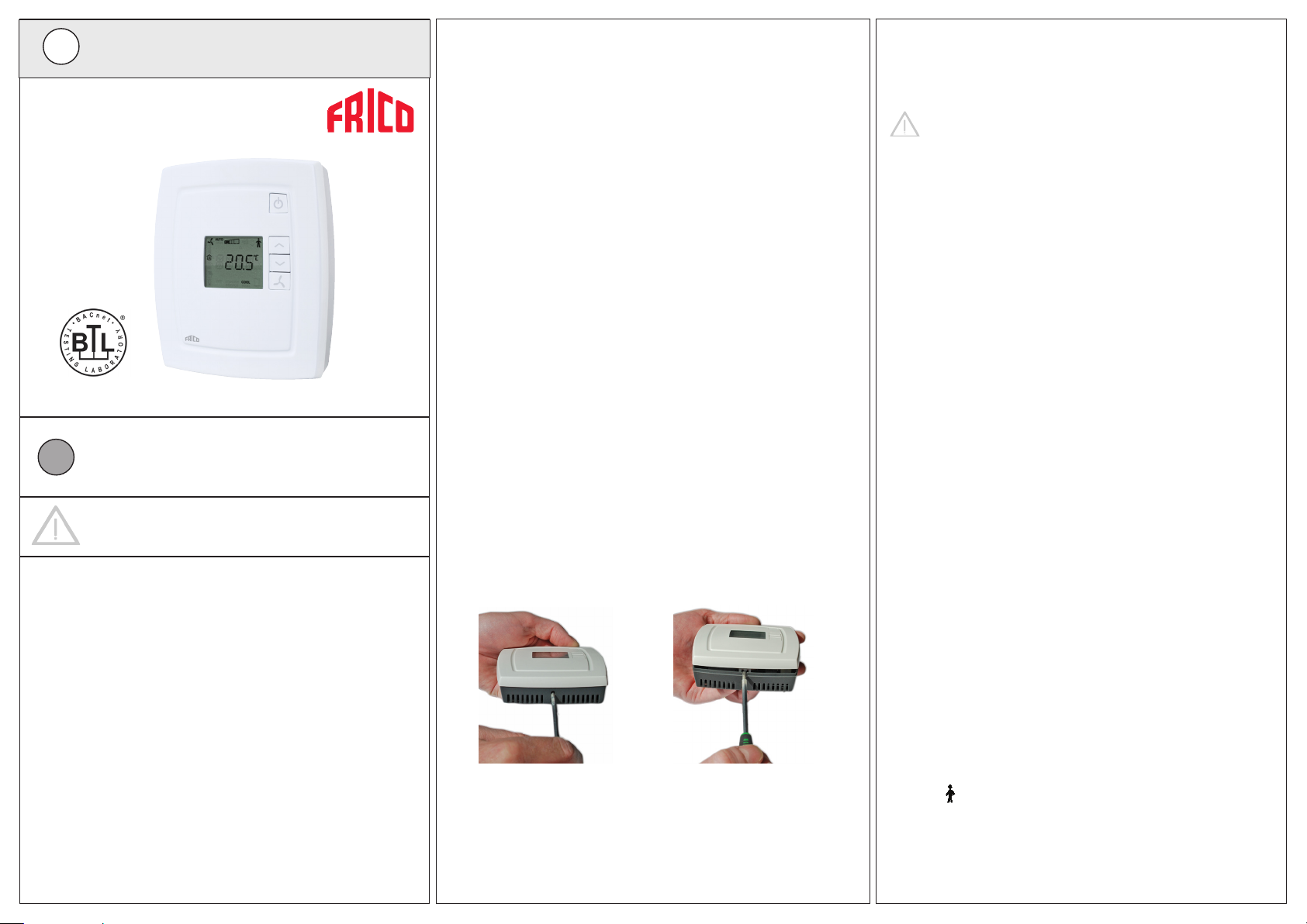
Depress the locking tab in the upper edge of the controller with a
screwdriver. Carefully turn the screwdriver until the bottom plate and the
electronics unit are slightly separated (see gure 1). Then use the cutout
that becomes visible in the edge of the bottom plate to open the upper
edge completely (see gure 2). Do the same thing in the lower edge of the
controller.
Figure 1 Figure 2
Lift the electronics unit up from the bottom plate. The bottom plate with
terminals has a number of hole combinations. Select suitable holes and
fasten the bottom plate on the wall or connection box, so that the arrows
on the bottom plate point upwards. Do not tighten the screws too hard!
FCR-230
Note: FCR-230 does not indicate fan breakdown or overheating of the
heating coil. Therefore, all connections must be made externally. An
overheating protection or similar can be used to disconnect the supply
voltage.
Disconnection
FCR-230 should be connected to a switch or circuit breaker in the
building installation. This switch should be in close proximity to the
controller and within easy reach of the operator, and should be
marked as the disconnecting device for the equipment.
Always use the circuit breaker to disconnect the controller from the
mains supply during maintenance of the fan-coil and actuators.
Settings
Control modes
FCR-230 can control heating and cooling in sequence or be set to
seasonal switching between heating and cooling (change-over, see
below).
Change-over function
FCR-230 has an input for change-over that automatically resets the
output DO4 to operate with heating or cooling function. When the controller is used together with a 3-position actuator, output DO5 is also
aected by the change-over function in accordance with the above. A
sensor of type PT1000 can be connected to the input and be mounted
so that it senses the temperature on the supply pipe to the coil.
When the temperature exceeds 28°C, the output function is set to
heating and when the temperature drops below 16°C, the output is
set to cooling. As an alternative, a potential-free contact can be used.
The input function can be set to NO/NC.
To ensure satisfactory functioning when using a sensor, the system
must have continuous primary circuit circulation. When the changeover function is not used, the input must be left disconnected.
When using an electric heater and the change-over function is set to
heating, the sequence of operation for FCR-230 will be heating/heat-
ing and DO5 will be activated rst.
If a change-over sensor is not connected, the sequence will be heating/heating. If cooling is to be used in the sequence, parameter 2
(change-over mode) must be changed manually.
Operating mode
There are four dierent operating modes. Switching between these
modes is performed locally.
Comfort: is shown in the display. Heating and cooling have a
smaller neutral zone NZC. An occupancy detector can be connected
to the DI in order to select between Comfort and Economy. Switching
between Comfort/Economy and O can also be done via the On/O
button. Comfort/Economy is selected via the parameter list.
1
Page 2
Economy (Standby): “Standby” is shown in the display. The heating and cooling setpoints are freely adjustable. Factory settings:
heating=15°C, cooling=30°C.
O: The controller does not heat or cool and the fan stops (unless
mould protection has been selected or the cool-down function for the
electric heater is running, in which case the fan will still run).
Window: is shown in the display, the controller is o and the fan
stops (unless mould protection has been selected or the cool-down
function for the electric heater is running, in which case the fan will
still run). The window contact is connected to the DI and must be
congured.
Occupancy detection
Parameter 3 determines if the DI is window contact input or
occupancy detection input. An occupancy detector can be connected
to the DI in order to switch between Comfort and Economy mode.
Setpoint
The setpoint is set using the INCREASE and DECREASE buttons.
Parameter 24 determines what is shown in the display. Refer to the
parameter list for details.
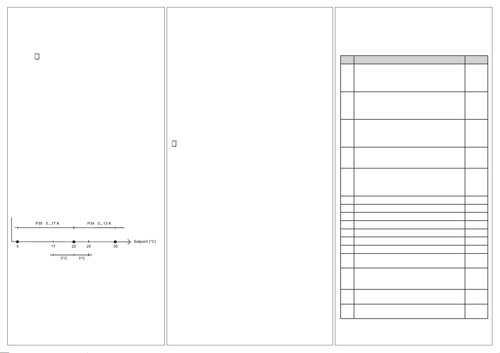
Setpoint limitation
In parameters 34 and 35, it is possible to set the maximum allowed
setpoint increase and decrease respectively.
Example: If P35=5 and P34=3, the setpoint can be changed between
17°C and 25°C (see the picture below).
The basic setpoint can be changed in parameter 64 (factory
setting=22°C).
Figure 3: Example of setpoint limitation
Fan control
The fan can be controlled via FCR-230 with the following modes: Low
speed, Medium speed, High speed, Auto. The current fan speed in
the Auto mode depends on the heating or cooling demand and the
settings for each speed.
When using automatic control, ”AUTO” is shown in the display.
The number of fan speed steps can be selected via parameter 30.
If the parameter is set to 1, the rst fan speed step will be used for fan
control.
Via parameter 31, it is possible to set the fan to the lowest speed level
when Auto mode is selected. If this parameter is set to 1, the fan will run
in all operating modes except O and Window (unless mould protection is
active or the cool-down function for the electric heater is running, in which
case the fan will run in these modes as well).
Manual control of the fan speed
By pressing the fan button, you change the fan speed according to the
sequence IàIIàIIIàAUTO. When using manual control, ”MAN” is shown
in the display.
If the fan has been congured not to be aected by the heating or cooling
demand, ”AUTO” will not be shown when pressing the fan button.
Indications
The display has the following indications:
HEAT Heating control
COOL Cooling control
The open window symbol is shown if this function has
been congured and a window is open.
OFF The controller does not heat or cool
On/O button
By pressing the On/O button, FCR-230 will switch between O mode
and Comfort/Economy mode.
Parameter list
When the controller is in Comfort mode or Window mode, dierent parameter values can be set in a parameter list.
Hold the INCREASE and DECREASE buttons depressed simultaneously
for about 5 seconds until the Service symbol is displayed and then press
the INCREASE button twice.
First the display will show parameter 1. Use the INCREASE and DE-
CREASE buttons to scroll between the parameters and press the On/O
button to select the desired parameter. The parameter number will then
be replaced by the parameter value. The value can be changed using the
INCREASE and DECREASE buttons. If a button is held depressed the
value will start scrolling, rst slowly and then with increasing speed.
To exit the parameter list and go back to the basic display, press the INCREASE button until “EXIT” is shown (one step before parameter 1) and
press the On/O button. You can also exit the parameter list by pressing
down the INCREASE and DECREASE buttons simultaneously.
Parameters
The following parameters can be changed in the parameter list.
Nº = parameter number
FS = factory setting
NO = normally open
NC = normally closed
Nº Description FS
1 Control mode:
2=2-pipe system
3=4-pipe system
4=(Electric heater) N/A
2 Change-over mode:
0=Heating control, 1=Cooling control, 2=Automatic
change-over depending on analogue temperature
sensor or digital input
3 Operating mode when activating digital input 1,
terminal 40/41:
0=Economy mode (occupancy detector)
1=O mode (window contact)
4 Mould protection:
0=Not active
1=Active (fan never stops)
5 Neutral zone at Comfort mode (NZC). If the neu-
tral zone is 2 K, the heating setpoint is equal to the
setpoint minus 1 and the cooling setpoint is equal
to the setpoint plus 1.
6 Heating setpoint when unoccupied 15°C
7 Cooling setpoint when unoccupied 30°C
8 P-band for the room controller 10 K
9 I-time for the room controller 300 s
10 Not used for this model
11 Switch o timer for Comfort mode 0 min
12 Switch on delay for Comfort mode 0 min
13 Sensor connected to AI1, terminal 42/43:
0=Internal sensor, 1=External room sensor
14 Sensor connected to UI1, terminal 43/44:
0=None, 1=Change-over digital, 2=Change-over
analogue
15 Type of digital actuator:
0=Thermal, 1=3-point
16-17Not used for this model
3
0
0
0
0 K
0
0
0
FCR-230
2
Page 3

Nº Description FS
18 Period time for heating actuator with
60 s
thermal actuator
19 Period time for cooling actuator with
60 s
thermal actuator
20 Runtime for heating actuator with increase/de-
120 s
crease actuator
21 Runtime for cooling actuator with increase/de-
120 s
crease actuator
22 Time in hours between exercise of heating actua-
23
tor
23 Time in hours between exercise of cooling actua-
23
tor
24 Setpoint or actual value shown in the display:
0
0=Actual, setpoint when changing the setpoint,
1=Actual, setpoint adjustment when changing the
setpoint, 2=Setpoint, 3=Only the setpoint adjustment
25 Conguration of fan control:
3
0=No control, 1=The fan is controlled by heating
requirement, 2=The fan is controlled by cooling
requirement, 3=The fan is controlled by heating
and cooling requirement
When using an electric heater, this parameter
should only be set to 1 or 3, or the heater may be
overheated.
26 Start signal in % of the controller output, heating
or cooling, for fan speed 1
20 (5
when
using an
electric
heater)
27 Start signal in % of the controller output, heating
60
or cooling, for fan speed 2
28 Start signal in % of the controller output, heating
100
or cooling, for fan speed 3
29 Hysteresis for start/stop of fans in % of the control-
5
ler output. (N/A)
30 Number of fan speeds (N/A) 3
31 Fan speed in the Auto mode:
0
0=The fan speed follows the cooling/heating
output, 1=The fan speed is minimum limited to
the lowest speed
32 Temperature compensation on AI1 0 K
Nº Description FS
33 Temperature compensation for the internal room
0 K
sensor
34 Highest permitted setpoint oset upwards. Set-
13 K
table value=0...13 K. Starting point=22°C.
35 Highest permitted setpoint oset downwards. Set-
17 K
table value=0...17 K. Starting point=22°C.
36 NO/NC digital input 1:
0
0=NO, 1=NC
37 NO/NC universal input 1:
0
0=NO, 1=NC
38 NO/NC digital output 4:
1
0=NO, 1=NC
39 NO/NC digital output 5:
1
0=NO, 1=NC
40 Manual/Auto heating output signal:
2
0=O, 1=Manual, 2=Auto
41 Manual/Auto cooling output signal:
2
0=O, 1=Manual, 2=Auto
42 Heating output signal in manual mode 0
43 Cooling output signal in manual mode 0
44 Model 45 Version Major 46 Version Minor 47 Released or beta version 48 Revision 49 Display backlight low 0
50 Display backlight high 30
51 EXOline PLA address 52 EXOline ELA address 53 Modbus address 254
54 Modbus communication parity bit:
2
0=No parity, 1=Odd parity, 2=Even parity
55 Modbus timeout for character (t1.5) in ms. Should
2 ms
be 1.5 times a character, i.e. at least 2 ms.
56 Modbus answer delay (t3.5) in ms. Should be 3.5
5 ms
times a character, i.e. at least 5 ms.
57 Communication protocol:
0
0=EXOline/Modbus, 1=BACnet MS/TP
58 BACnet MS/TP MAC address
-
0-127=master address, 128-254=slave address
Nº Description FS
59 The 4 low numbers in the BACnet device ID,
-
0-9999
60 The 3 high numbers in the BACnet device ID 61 BACnet MS/TP Max. master 127
62 Communication protocol speed:
0
0=9600 bps, 1=19200 bps, 2=38400 bps,
3=76800 bps (alternative 3 only applies to BACnet)
63 Resets communication parameters (not address-
0
es) to their factory settings:
1=Factory settings (EXOline/Modbus@9600)
64 Basic setpoint. Settable value=5...50°C. 22°C
Recommended settings for Frico convectors:
Nº TKW heat TKW cool TKW change over
2 0 (FS) 1 2
14 0 (FS) 0 (FS) 2
31 0 (FS) 0 (FS) 0 (FS)
Nº SL/SLS R
heat
SL/SLS R
cool
SL/SLS R
change over
2 0 (FS) 1 2
14 0 (FS) 0 (FS) 2
31 1 1 1
Wiring
20
10
POWER
LOGIC
40
Figure 4: Bottom plate connections
30
50
FCR-230
3
Page 4

BLU-BLUE
BIANCO-WHITE
GRIGIO-GREY
VIOLA-VIOLET
V
G
FACTORY WIRING
SAFETY MICRO FLOAT
FAN MOTOR INTERNAL UNIT
DRAIN PUMP
ADDITIONAL WIRING
EELECTRIC VALVE
FS
PS
IFM
VPTK
SUPPLY TERMINAL BLOCK
TB
COLORE CAVI WIRE COLOURS
B
MARRONEBROWN
NEROBLACK
ROSSORED
ORANGE
CWR
O
YELLOW/GREEN
Y/G
A
FCR230
HEATING INPUT SIGNAL ( 230V a.c.)
230V - 1~ - 50Hz
N
L
D04
COOLING INPUT SIGNAL ( 230V a.c.)
33 D05
44 AGnd
41 Al
2 ÷ 10Vd.c.
50 A01
50 AGnd
+
-
AO1
Figure 8: External placement
B
Modbus
EXOline
M
BACnet
Connection of dierent actuators
FILTER
L N PE
AB Y/G
(cool) (heat)
VPTK VPTK
0 V Y
EC fan
When connecting thermal actuators, DO4 is used for heating actuators and DO5 for cooling actuators. If the installation is a 2-pipe
installation and the change-over function is used, the actuator should
be connected to DO4.
When connecting 3-point actuators, DO4 is used for increase signal
and DO5 for decrease signal, even when the change-over function is
used.
TKW
Figure 5: Connection diagram
~ ~ YX Y1 Y2 Y3 Y4 L L N N PE
1TB
Y/G
B
A
O
4 3 2 1
4 3 2 1
G
1CF
1CM
Y/G
B
W
1IFM
W
CR
B
1PS
11
A
G
O
FS
35 35
2LIV 1LIV
C
N L PE
X3
P15V
A+
AP+
P-
W V U TP TP
X2
M1 M2
INVERTER
BLAC
RS232
1PCB
B
C
ECGT1
A
Figure 6: Connection diagram with water heater
M
Modbus
EXOline
BACnet
10 L 230 V AC Line Power supply
11 - Not connected
12 N 230 V AC Neutral Power supply (internally con-
nected to terminal 13)
13 N Fan-coil common /
230 V AC Neutral
Common fan-coil connector (internally connected to
terminal 12)
20 DO1 Fan-coil output 1
Relay, 230 V AC*, 3 A
for fan control
21 DO2 Fan-coil output 2
Relay, 230 V AC*, 3 A
for fan control
22 DO3 Fan-coil output 3
Relay, 230 V AC*, 3 A
for fan control
ECGT1
30 - Not connected
31 DO4 Digital output 4 for
heating/cooling
or opening with
Digital output. 230 V AC, max
300 mA. Max 2 A during 20
ms.
3-point actuator
32 CDO45 Common DO4 & 5 Common connection for
Figure 7: internal placement
FCR-230
digital outputs 4 and 5
4
Page 5

33 DO5 Digital output 5 for
cooling or closing
with 3-point actuator.
40 DI Digital input Potential-free window contact
41 Agnd Analogue ground
42 AI Analogue input External PT1000 instead of
43 UI Universal input Change-over input. Potential-
44 Agnd Analogue ground
50 Agnd Analogue ground
51 - Analogue out A0I EC fan
52 - Not connected
53 A RS485 communication A
54 B RS485 communication B
*The sum of the current through DO1-DO3 is protected by a fuse
Digital output. 230 V AC, max
300 mA. Max 2 A during
20 ms.
or occupancy contact. Con-
gurable for NO/NC.
the internal NTC
free switch (congurable for
NO/NC) or PT1000.
Low Voltage Directive (LVD) standards / EMC emissions &
immunity standards
This product conforms to the EMC and LVD requirements in the
European harmonised standards EN 60730-1:2000 and EN 60730-29:2002 and carries the CE mark.
RoHS
This product conforms to the Directive 2011/65/EU of the European
Parliament and of the Council.
Contact
Frico AB, Industrivägen 41, 433 61 Sävedalen, Sweden
Tel: +46 31 336 86 00, Fax: +46 31 26 28 60
www.frico.net, mailbox@frico.se
SE
i
Instruktion för produkter med mjukvaruversion 1.2.
Läs denna instruktion innan produkten monteras
och ansluts. Produkten är BTL-godkänd fr.o.m.
mjukvaruversion 1.2-1-00 (BACnet-stack 3.0.4).
Följ alltid de anvisade säkerhetsföreskrifterna i
dokumentationen för att förebygga risken för brand,
elstöt och personskador
INSTRUKTION
FCR-230
Rumsregulator för styrning av fan-coil-enheter
FCR-230 är en rumsregulator avsedd att styra fan-coil-värmare/kylare och
termiska ställdon eller 3-punktsställdon. Montage sker direkt på vägg eller
eldosa. Fläkthastigheten kan regleras i tre steg.
FCR-230 har change-over-funktion och kan användas för 2-rörs- eller
4-rörssystem.
FCR-230 har kommunikation via RS485 (Modbus, BACnet eller EXOline)
för inbyggnad i system. Apparaten kan kongureras via verktyget Regio
tool (version 1.3-1-05 eller senare), som kan laddas ner kostnadsfritt från
Regins hemsida (www.regin.se).
Tekniska data
Matningsspänning 230 V AC ±10 %, 50/60 Hz
Egenförbrukning < 3 W
Omgivningstemperatur 0...50°C
Omgivande fuktighet Max. 90 % RH
Lagringstemperatur -20...+70°C
Inbyggd temperaturgivare Typ NTC, mätområde 0...50°C
Ingångar Se inkopplingsbilder och tabell nedan
Utgångar Reläer för äktstyrning, 230 V AC, 3 A
DO4, DO5 för ställdon, Triac, 230 V AC,
max. 300 mA
Kommunikation RS485: Modbus, EXOline (automatisk
detektering/omkoppling) eller BACnet
Modbus 8 bitar, 1 eller 2 stoppbitar. Udda, jämn
(FI) eller ingen paritet
Kommunikationshastighet 9600, 19200, 38400 bps (EXOline, Modbus
och BACnet) eller 76800 bps (endast
BACnet)
Skruvplint Av hisstyp för kabelarea max 2,1 mm
Skyddsklass IP20
Nedsmutsningsgrad 2
Överspänningskategori 3
Material hölje Polycarbonat, PC
Mått 102 x 120 x 29 mm
2
Installation
Montera regulatorn på en plats med för rummet representativ temperatur. Lämplig placering är ca 1,6 m över golvet, utan omgivande
hinder för luftcirkulation.
Tryck in låshaken i överkanten av regulatorn med en skruvmejsel.
Vrid försiktigt på mejseln tills bottenplattan och elektronikenheten
delar något på sig (se gur 1). Använd sedan det hack som blir synligt
i kanten av bottenplattan för att öppna överkanten helt (se gur 2).
Gör samma sak i underkanten av regulatorn.
Figur 1 Figur 2
Lyft ur elektronikenheten ur bottenplattan. Bottenplattan med
anslutningskontakter har ett antal hålbilder. Välj passande hålbild
och skruva fast bottenplattan på vägg eller eldosa, så att pilarna i bottenplattan pekar upp. Dra inte skruvarna för hårt!
OBS: FCR-230 har ingen indikering som visar om äkten går sönder
eller om värmebatteriet är överhettat. Därför måste alla kopplingar
FCR-230
5
 Loading...