

Page 1
Original instructions
Control system FC
Standalone level - FC111, FC113
SE
.... 6
NO
.... 13
GB
.... 20
Page 2
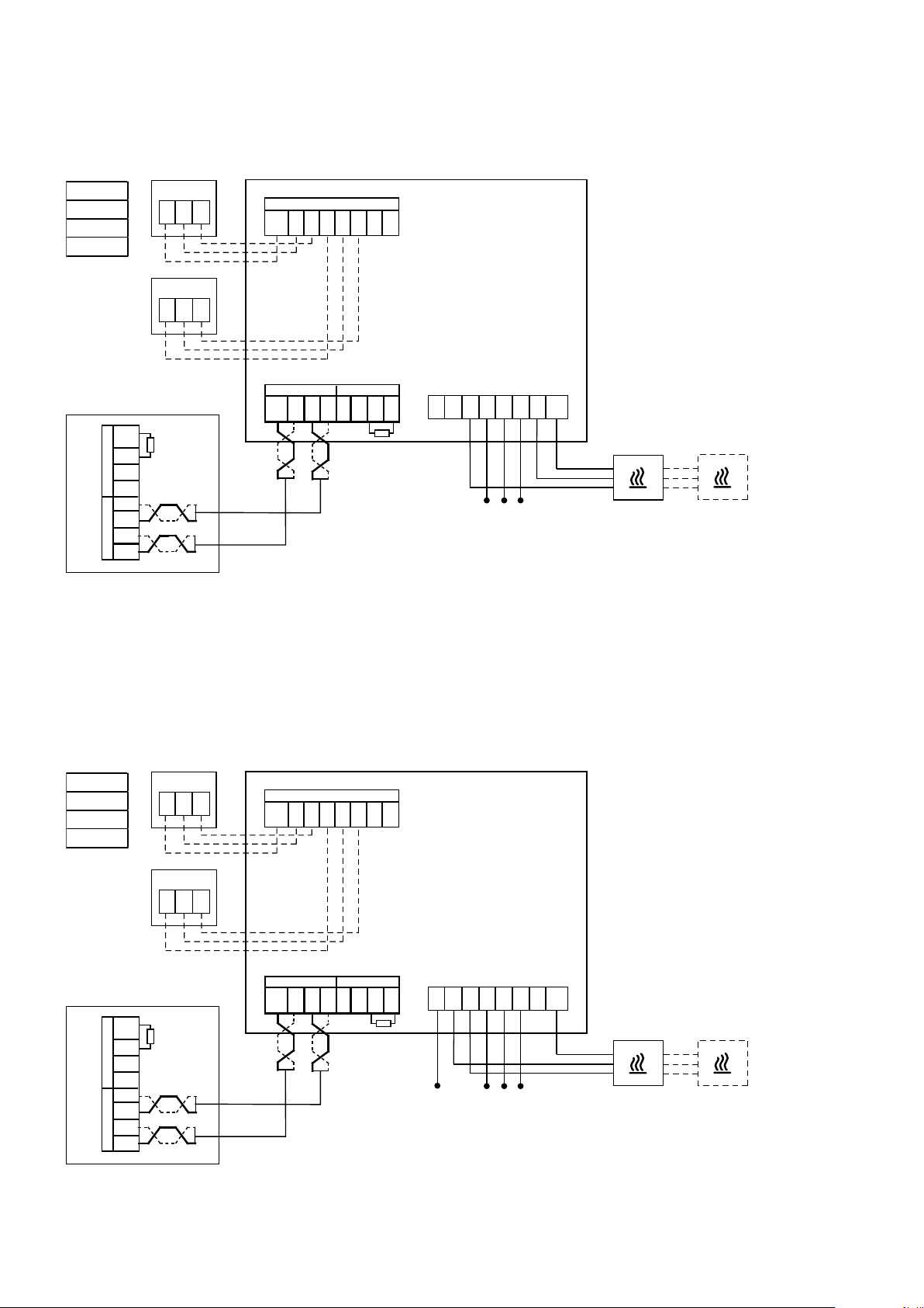
FC111
Sensor
FCOTX
Sensor
FCOTX
230V~
FC111/113
FCBB
FCRTX
BUS 2
BUS 1
LO
HI
+12V
GND
LO
HI
+12V
GND
Sensor
G12
Sensor
G12
FCCH
A1 A2 B1 B2
GND
GND
GND
BUS 1 BUS 2
HI
LO
+12V
FCPOBH
OUT
GND
0-10V
LO
L2 L2 PE PE L
HI
GND
+12V
230V~
IN
NN
L
OUT
Max 16A
400V2~
FCBB
FCRTX
+12V
BUS 2
GND
+12V
BUS 1
GND
Sensor
G12
A1 A2 B1 B2
GND
GND
GND
OUT
0-10V
FCPOBH
Sensor
G12
BUS 1 BUS 2
HI
GND
LO
HI
LO
HI
FCCH
+12V
HI
LO
GND
+12V
LO
L2 L2 PE PE L
400V2N~
IN
NN
L
OUT
Max 16A
2
Page 3
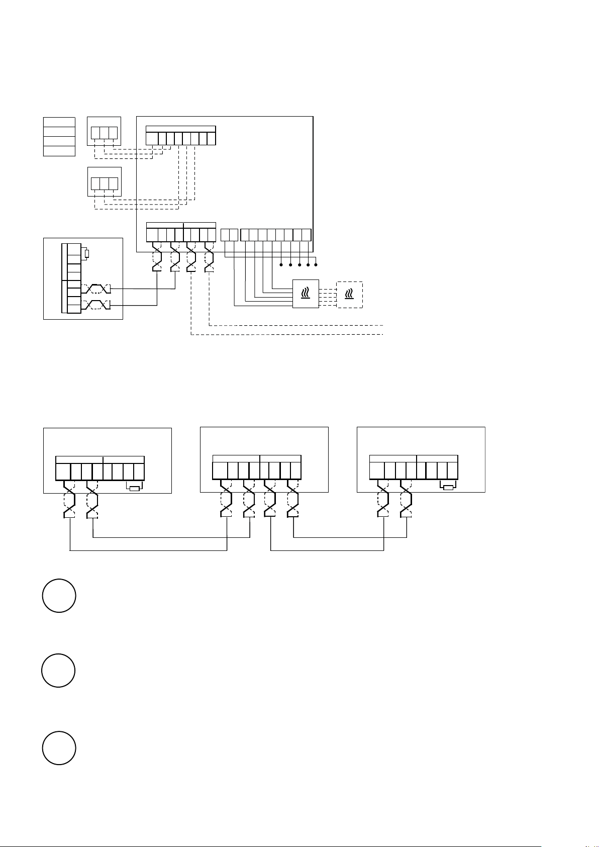
FC113
Sensor
FCOTX
400V3~
FC111/113
Sensor
FCBB
FCRTX
BUS 2
BUS 1
LO
HI
+12V
GND
LO
HI
+12V
GND
G12
Sensor
G12
FCCH
A1 A2 B1 B2
GND
GND
BUS 1 BUS 2
HI
LO
GND
+12V
OUT
GND
0-10V
HI
LO
PE
GND
+12V
PE
FC111/113 - FCPOBH/FCPOB3H
NNUVWL1L3 L2
Max 3x13A
FCPOB3H
400V 3N~
FCPOBH/FCPOB3H
BUS 1 BUS 2
GND
SE
NO
GB
+12V
BUS 1 BUS 2
HI
HI
LO
GND
+12V
LO
HI
+12V
LO
GND
HI
+12V
LO
GND
BUS 1BUS 2
HI
+12V
LO
GND
GND
+12V
HI
LO
För att minska risken för störningar ska kommunikationsbussen vara terminerad (avslutad) i
vardera änden dvs. i de enheter som sitter i början respektive i slutet av bussen. Vid leverans
är alla bussar förterminerade med ett 120 Ohms motstånd mellan HI and LO på BUS2. Vid
vidarekoppling tas motståndet bort.
Som alternativ till resistans kan termineringsswitchen på kortet sättas i läge ”ON”.
For å redusere faren for forstyrrelser skal kommunikasjonsbussen være terminert (avsluttet) i
hver ende, dvs. i de enhetene som er plassert i begynnelsen henholdsvis i slutten av bussen. Ved
levering er alle busser på forhånd terminert med en motstand på 120 Ohm mellom HI og LO på
BUS2. Ved viderekobling fjernes motstanden.
Som alternativ til resistans kan termineringssvitsjen på kortet settes i stillingen ”ON”.
To reduce the risk of interference, the communication BUS should be terminated at each end, i.e. in
the units that are located at the start and at the end of the BUS respectively. On delivery, all buses
are pre-connected with a 120 Ohm resistor between terminals HI and LO on BUS2. When making
further connections, remove the resistor.
As an alternative to resistance, the termination switch on the board can be set to the "ON" position.
3
Page 4
FC111/113
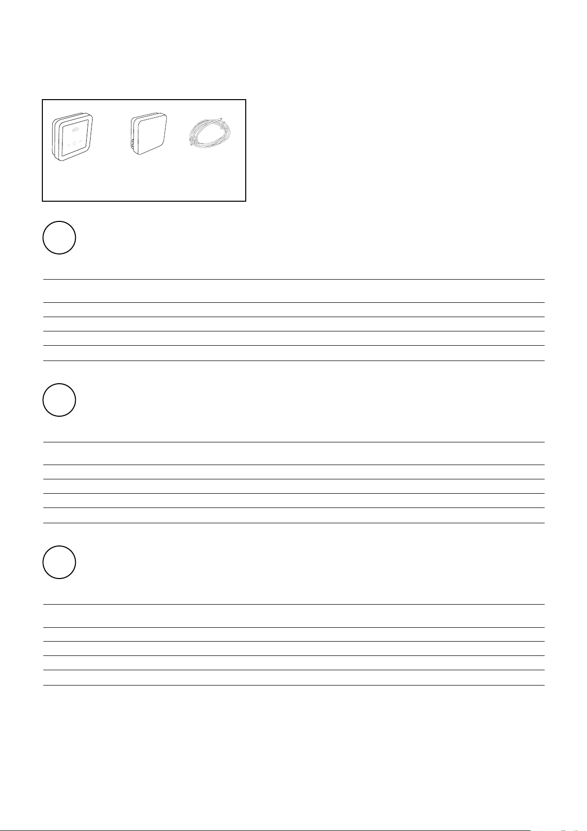
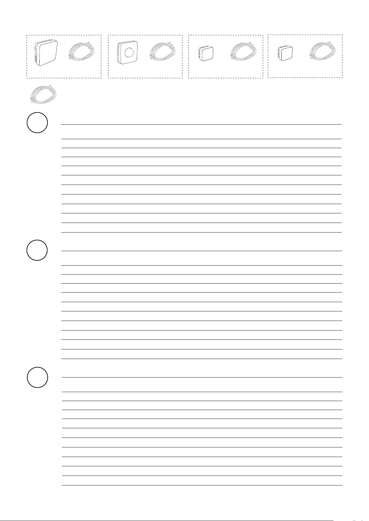
FC111, FC113
FCB05
FCCH FCPOBH
FCPOB3H
FC111 / FC113
SE
Ingående komponenter
Ty p Ingår i Beskrivning HxBxD
[mm]
FCCH FC111/FC113 Kontrollpanel, IP44 89x89x26
FCPOBH F C 111 Styrenhet, 16A, 230V~/400V2~, IP44 105x105x38
FCPOB3H FC113 Styrenhet, 3x13A, 400V3~, IP44 149x149x43
FCBC05 FC111/FC113 Kommunikationskabel, 5 m L: 5 m
NO
Inngående komponenter
Type Inngår i Beskrivelse HxBxD
[mm]
FCCH FC111/FC113 Kontrollpanel, IP44 89x89x26
FCPOBH F C 111 Styreenhet, 16A, 230V~/400V2~, IP44 105x105x38
FCPOB3H FC113 Styreenhet, 3x13A, 400V3~, IP44 149x149x43
FCBC05 FC111/FC113 Kommunikasjonskabel, 5 m L: 5 m
GB
Components included
Type Included in Description HxWxD
[mm]
FCCH FC111/FC113 Control panel, IP44 89x89x26
FCPOBH F C 111 Control box, 16A, 230V~/400V2~, IP44 105x105x38
FCPOB3H FC113 Control box, 3x13A, 400V3~, IP44 149x149x43
FCBC05 FC111/FC113 Communication cable, 5 m L: 5 m
4
Page 5
FC111/113
FCPOBH / FCPOB3H
FCBC05/10/25
FCSC10/25
Tillval
SE
Ty p Beskrivning HxBxD
FCPOBH Styrenhet för systemutbyggnad, 16A, 230V~/400V2~, FC111, IP44 105x105x38
FCPOB3H Styrenhet för systemutbyggnad, 3x13A, 400V3~, FC113, IP44 149x149x43
FCBB Svartkroppsgivare, IP44 89x89x43
FCRTX Extern rumstemperaturgivare, IP20 39x39x23
FCOTX Utetemperaturgivare, IP44 39x39x23
FCBC05 Extra kommunikationskabel, 5 m L: 5 m
FCBC10 Extra kommunikationskabel, 10 m L: 10 m
FCBC25 Extra kommunikationskabel, 25 m L: 25 m
FCSC10 Extra givarkabel, 10 m L: 10 m
FCSC25 Extra givarkabel, 25 m L: 25 m
FCBC10
FCSC10
FCBB FCRTX
FCSC10
FCSC10
FCOTX
[mm]
NO
GB
Ekstrautstyr
Type Beskrivelse HxBxD
[mm]
FCPOBH Styreenhet for systemutbygging, 16A, 230V~/400V2~, FC111, IP44 105x105x38
FCPOB3H Styreenhet for systemutbygging, 3x13A, 400V3~, FC113, IP44 149x149x43
FCBB Black bulb sensor, IP44 89x89x43
FCRTX Ekstern romtemperaturføler, IP20 39x39x23
FCOTX Utetemperaturføler, IP44 39x39x23
FCBC05 Ekstra kommunikasjonskabel, 5 m L: 5 m
FCBC10 Ekstra kommunikasjonskabel, 10 m L: 10 m
FCBC25 Ekstra kommunikasjonskabel, 25 m L: 25 m
FCSC10 Ekstra giverkabel, 10 m L: 10 m
FCSC25 Ekstra giverkabel, 25 m L: 25 m
Options
Type Description HxWxD
[mm]
FCPOBH Control box for system extension, 16A, 230V~/400V2~, FC111, IP44 105x105x38
FCPOB3H Control box for system extension, 3x13A, 400V3~, FC113, IP44 149x149x43
FCBB Black bulb sensor, IP44 89x89x43
FCRTX External room temperature sensor, IP20 39x39x23
FCOTX Outdoor temperature sensor, IP44 39x39x23
FCBC05 Extra communication cable, 5 m L: 5 m
FCBC10 Extra communication cable, 10 m L: 10 m
FCBC25 Extra communication cable, 25 m L: 25 m
FCSC10 Extra sensor cable, 10 m L: 10 m
FCSC25 Extra sensor cable, 25 m L: 25 m
5
Page 6

GB
FC111/113
Start up
1. Check that all components and accessories are
enclosed.
2. Assemble and connect system, consult wiring
diagrams.
3. Power-up the system.
4. The system automatically identifies all components,
even when they are added at a later stage.
System solution
A system consists of a control panel, FCCH, as well as an
optional number of control units, FCPOBH/FCPOB3H (1-63
units), sensors and heaters. The set-point temperature for
the system is selected on the control panel.
In the system, groups are created that comprise one
FCPOBH/FCPOB3H, sensor and heater. At most, each group
can consist of one or more heaters with a total rated current
of 16A (FCPOBH) or 3 x 13A (FCPOB3H).
The control panel houses a built-in temperature sensor
which can be used, alternatively the groups which are fitted
with external room temperature sensors have better sensor
positioning for local temperature control per group.
A. System without external room sensors
The control panel's temperature sensor is
controlling.
B. System with one external room sensor
One external room temperature sensor in
the system controls all groups.
C. System with several groups of external
room sensors in each group
External room temperature sensors
control each group.
D. System with several groups, of which,
at least two groups have external room
sensors and at least one group does not
have an external room sensor
External room temperature sensors control
each group.
Group/groups without sensors are controlled
by the control panel's temperature sensor.
Black bulb sensor
With black bulb sensors, the operative temperature is
measured and the control adapted to suit radiant heaters.
When the black bulb sensors are connected (accessory
FCBB), the system will automatically detect this and the
room value will be recorded from the black bulb sensor.
Heating blocked dependent on outdoor temperature
With outdoor temperature sensors (accessory FCOTX),
heating is automatically blocked when the outdoor
temperature exceeds 15 °C. This function can be
deactivated, see Settings.
20
Page 7
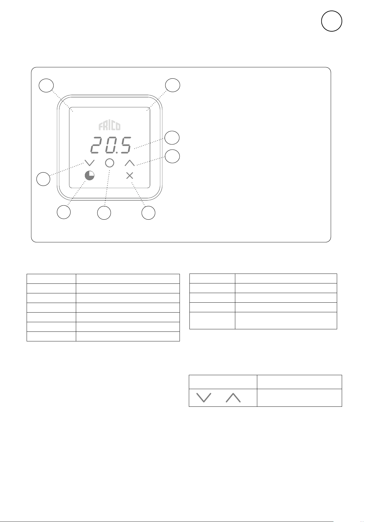
Control panel
Overview
FC111/113
GB
7
8
Keypad
1 Increase
2 Decrease
3 Menu / OK / Confirm
4 Timer
5 Cancel / Back
6
4 and 5 appear on the first press of menu
1
2
4
3
5
button.
Screen
6 Current room temperature (standby mode) /
Set point temperature (active mode)
Indicators
7 Operating mode
8 Status
Indicator Operating Mode (left-hand LED)
Colour (LED) Operating mode
OFF
White
White flashing
Green
Green flashing
Yellow
Normal mode
Comfort mode
Comfort mode - temporary
Reduced (night mode)
Reduced (night mode) - temporary
Timer
During start-up, the text Inlt appears on
screen, then the current room temperature is
displayed.
When the screen is in standby mode, the light
intensity is reduced. Pressing any button will
simply display the set point temperature.
The FC111/113 is delivered with preset values.
The preset set point temperature is 21 °C
and can be easily adjusted using the up/down
arrows. The FC111/113 can also be adjusted to
your own requirements, consult the following
pages.
Indicator Status (right-hand LED)
Colour (LED) Status
White
OFF
Red flashing
Purple
Display lock
Press and hold (2 sec) Quick command
+
Heat on
Heat off
Alarm
Heating blocking
Display lock on/off
21
Page 8

GB
FC111/113
Timer
The set point temperature can be changed for
a limited period using the timer (15 minutes
to 45 days).
Press to activate keypad.
Press to start timer at the preset values
(1 h, 24 °C) or the most recently used
values).
Or to adjust the time and temperature values:
Press and hold for 2 seconds.
Set the desired time.
User menu
Press and hold for 2 seconds.
Home screen
Browse between the menu options.
Confirm
See the table on the following page for the choices
which are possible.
15 minutes - 45 days (’ minute, h hour, d day)
Confirm
Set the desired room temperature (set
point temperature).
Confirm
While the timer is counting down, the
screen alternates between displaying
the time remaining and the set point
temperature. The current temperature is
not shown in the timer mode.
When time is up the unit returns to previous
settings.
22
Page 9

User menu
FC111/113
GB
Functions Menu
options
dAtE -
tHi 21 °C
tLo 18 °C
Prog
HEAt
For week program.
Set the following:
- year
- month
- day
- time (00:00)
For week program. Set the desired room
temperature (set point temperature) for
comfort mode.
For week program. Set the desired room
temperature (set point temperature) for
reduced mode.
Weekly program, see separate section.
Switch heating on/off.
Default
settings
(off)
(function
not activated)
On (on)
Description
Increase/decrease with up/down
arrow. Confirm each step with
OK.
Increase/decrease with up/down
arrow. Confirm with OK.
Increase/decrease with up/down
arrow. Confirm with OK.
Switch between (OFF) and P1-P9
with up/down arrow. Confirm
with OK.
Switch between (On) and (OFF)
with up/down arrow. Confirm
with OK.
AL A -
AL H -
OFF -
SEt -
Display active alarm.
Display alarm history.
Switch off the system. To switch off the system, select
Change settings, see separate section Settings.
Switch between alarms with up/
down arrow. To see the serial
number for an alarm, press OK.
If no alarm: no A.
Switch between alarms with up/
down arrow. To see the serial
number for an alarm, press OK.
If no alarm: no A.
(OFF) using OK. Wait 10 sec.
The system is then switched on
by pressing OK and selecting
(On) with up/down arrow and
confirming with OK.
CLr -
Factory reset. Resets values to factory settings.
Press OK. Select (YES), by keeping OK depressed for 2 seconds
(countdown).
23
Page 10

GB
FC111/113
Week program
The FC has nine preset weekly programs (P0/
P1-P9).
To activate weekly program, the following must be
set in the user menu:
- Date (dAtE)
- Temperature, comfort mode (tHi)
- Temperature, reduced mode (tLo)
The adaptive start function allows the control
to learn when it needs to start in order to
attain a given set point temperature at a given
time of the day in the environment in which
it is used. This function can be deactivated
(see Settings menu).
Preset programs
Setting week programs
Weekly program is selected and activated in User
Menu:
Press and hold for 2 seconds.
Browse to Prog.
Confirm
Selection of preset program P0/P1 - P9
Select P0/P1-P9.
Confirm to start the program.
Comfort mode
Description
P0, P1 05:30 - 08
P2 06:30 - 10
P3 06 - 09
P4 06 - 22
P5 17 - 23
P6 06 - 18
P7 09 - 21
P8 09 - 22
P9 09 - 18
*) Other times: Reduced (night mode)
Residence
Residence,
late
Residence,
short
Residence,
day only
Weekend
Office
Office, late
Shop, late
Shop
*
Mon-Fri:
Sat-Sun:
Mon-Fri:
Sat-Sun:
Mon-Fri:
Sat-Sun:
Mon-Sun:
Fri:
Sat-Sun:
Mon-Fri:
Mon-Fri:
Mon-Fri:
Sat-Sun:
Mon-Fri:
Sat-Sun:
17 - 22
07 - 23
19 - 23:30
07:30 - 23:30
16 - 23
07 - 23
07 - 23
09 - 20
09 - 14
Temporarily override the weekly program
It is easy to temporarily disregard the set point
temperature which is preset in the weekly program.
Set the desired temporary set point
temperature.
Confirm
The temporary set point temperature will apply until
the next program step.
Power failure
Note! A power loss longer than 7 days may
require an adjustment of time and date.
The week program is affected if the clock is
not correctly set.
24
Page 11

Settings
Settings are changed in User Menu:
Press and hold for 2 seconds.
Browse to SEt.
FC111/113
Enter the number for the setting that will be
changed using up/down arrows, confirm each digit
with OK. See table.
GB
Confirm
Enter password using up/down arrows, confirm
each digit with OK. Password: 1932.
Settings
#
547
360
359
Functions Default settings
Adaptive start
Airing mode*
Airing mode*, blocking time
1 (function activated)
1 (function activated) 0 (function not activated) / 1 (function activated)
900 sec 300 - 6000 sec
Select desired value according to table.
Confirm
Description
0 (function not activated) / 1 (function activated)
See weekly program.
374
376 150 (15.0 °C) -200 - +400 (-20.0 - +40.0 °C)
438
*Airing mode, which saves energy, e.g. when windows are open. With the preset values: Should there be
a sudden drop in temperature, e.g. when opening a window, the set point temperature is lowered to 10 °C
for 900 sec (15 min). If the temperature does not drop any further after this, the control will return to the
previous setting.
Heating blocking
Heating blocking,
Temperature
Daylight saving/summer time and winter
time.
1 (function activated) 0 (function not activated) / 1 (function activated)
Heating blocking, which requires outdoor sensor (accessory FCOTX).
Heating blocking, which requires outdoor sensor (accessory FCOTX).
1 (function activated) 0 (function not activated) / 1 (function activated)
Automatic time change-over.
Ensure that the product still satisfies Ecodesign Regulation's requirements when functions are
deactivated.
25
Page 12
GB
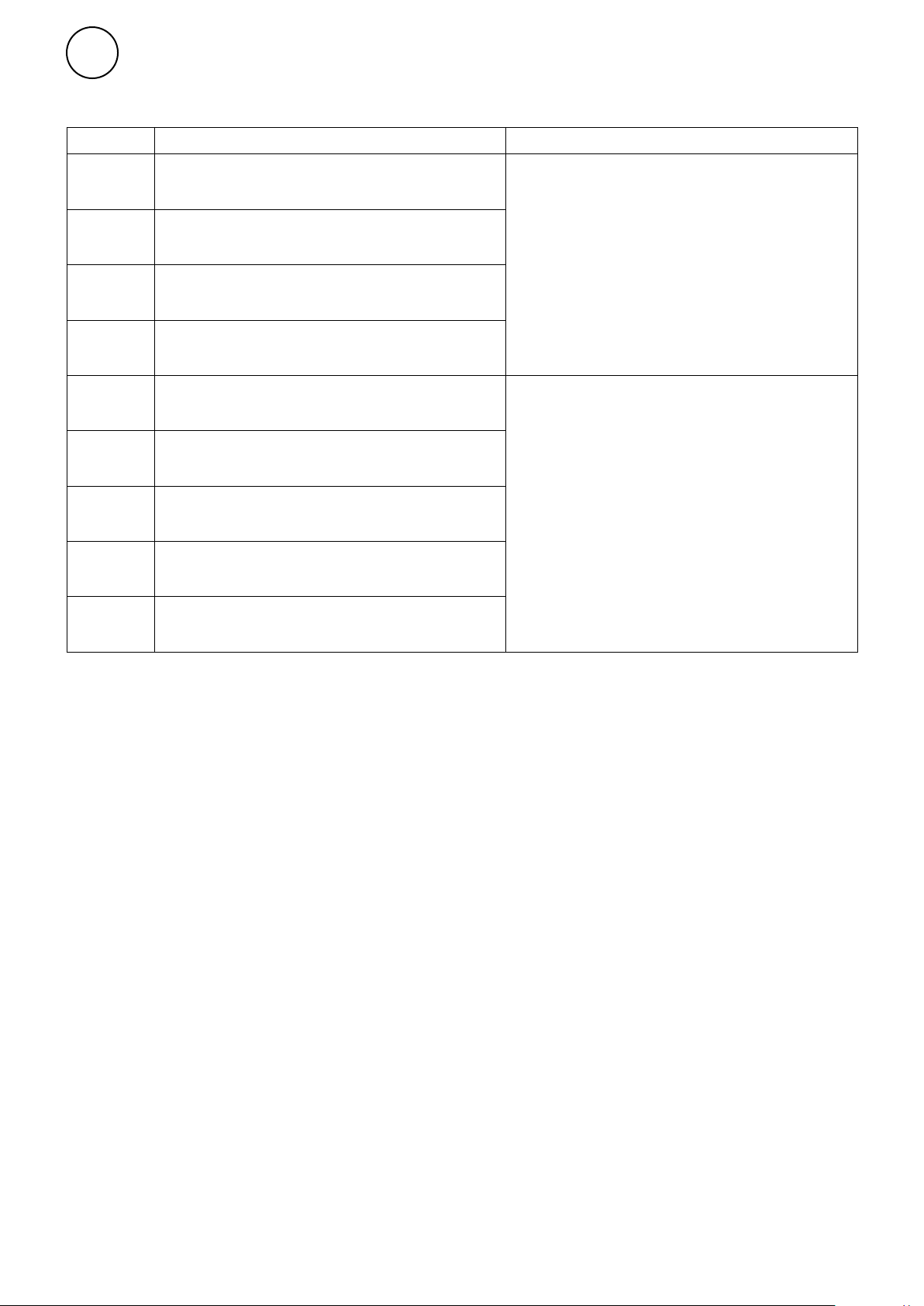
Trouble shooting
Error code ActionCause
A 5
A 8
A 12
A 14
Contact lost with control panel or
control unit
Contact lost with external room temperature
sensor
Contact lost with outdoor temperature sensor
Contact lost with black bulb sensor
FC111/113
• If the component is removed
intentionally, the alarm must be reset
manually. See below.
• Check the connections.
• The alarm resets automatically, if the
component is detected again.
• If the alarm persists after resetting,
contact Frico.
A 7
A 9
A 10
A 11
A 13
External room temperature sensor fault
Fault on the control panel's temperature
sensor
Incorrect sensor connection
Outdoor temperature sensor fault
Black bulb sensor fault
• Check the connections.
• If the alarm persists after resetting,
contact Frico.
When error codes are displayed, the system continues to
operate with the components that are functioning. If all
room temperature sensors, including the temperature sensor
in the control panel, have lost contact, the system will run at
25% heat output.
If the problems continue, please contact Frico for support.
Reset alarm
To reset manually, press X for 2 seconds where the serial
number for an alarm is displayed (see User Menu). The
majority of the alarms reset automatically, once the problem
is corrected.
26
Page 13

Page 14

Main offi ce
Frico AB Tel: +46 31 336 86 00
Industrivägen 41
SE-433 61 Sävedalen mailbox@frico.se
Sweden www.frico.net
For latest updated information and information
about your local contact: www.frico.net.
Art.no 157809, 20210224, HH/CH
 Loading...