

ERP
INSTRUKTION INSTRUKTION
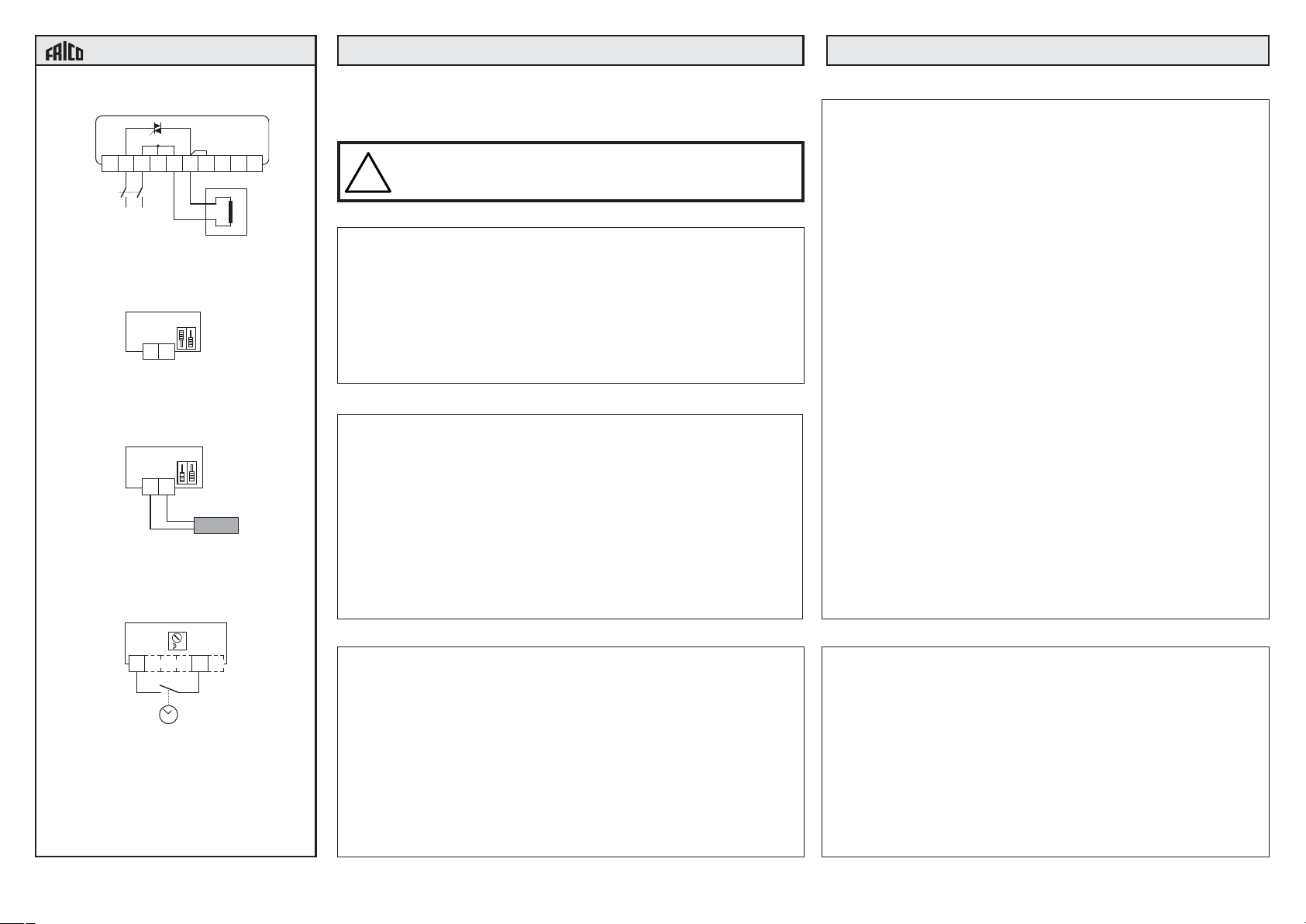
K
1
2 U
3 4
U
K G G
Fig 1: Inkoppling av matnings-
spänning och belastning.
G
G
Fig 2: Omkopplarinställning vid
intern givare.
G
G
ERPGG
ERPRG
Fig 3: Omkopplare och anslutning
vid extern givare.
Triac-regulator för steglös styrning
av elvärme
Läs noga igenom denna instruktion innan produkten installeras och
!
tas i bruk. Spara den sedan på säker plats för senare användning.
ERP är en komplett steglös effektregulator för elvärmestyrning med
automatisk spänningsanpassning. Omkopplingsbar för drift med
inbyggd eller extern temperatursensor. Regulatorn arbetar steglöst
genom tidsproportionell styrning - Förhållandet mellan tilltid och fråntid
avpassas efter det rådande effektbehovet.
ERP är endast avsedd för elvärmestyrning. Reglerprincipen gör att
den inte kan användas till motor- eller belysningsstyrning.
OBS: ERP kan inte användas för styrning av 3-fas värmare, eftersom
endast en fas regleras.
Reglerprincip
ERP pulsar hela den tillkopplade effekten Till-Från. PULSER
anpassar medeleffekten till det rådande effektbehovet genom att
steglöst anpassa förhållandet mellan Till-tid och Från-tid.
Pulsperioden (= summan av Till-tid och Från-tid) är fast 60 sek.
ERP är nollgenomgångsstyrd för att eliminera radiostörningar.
ERP anpassar automatiskt reglermetod efter reglerobjektets
dynamik.
Vid snabba förlopp, t. ex. tilluftreglering kommer ERP att arbeta
som PI-regulator med ett fast
P-band på 20K och en fast I-tid på 6 minuter.
Vid långsamma förlopp t. ex. rumsreglering kommer ERP att arbeta
som P-regulator med ett fast P-band på 1.5K
Elinstallation
Installationen, som skall föregås av en allpolig brytare med ett
brytavstånd om minst 3 mm, skall utföras av behörig installatör .
Matningsspänning (fig 1)
Plint 1 och 2. Polaritetsoberoende.
Matningsspänning: 200 - 415V AC, 50 - 60 Hz med automatisk
spänningsanpassning.
Max ström: 16A.
Belastning (fig 1)
Plint 3 och 4.
Resistiv en- eller två-fas värmare.
Max belastning: 3680W vid 230V (16A)
6400W vid 400V (16A)
Min belastning: 230W vid 230V (1A)
400W vid 400V (1A)
OBS: Kylflänsen är spänningsförande.
Extern givare (fig 2 - 3)
Plint G och G. Polaritetsoberoende.
OBS: Vid drift med extern givare måste motsvarande funktion
kopplas bort i ERP . Dett a görs genom att ställa skjutomkopplarna till höger om plintraden i enlighet med figur 3.
OBS: ERP-givarna har hög potential mot noll och jord (>200V).
Anslutning av extern givare skall alltså följa gällande föreskrifter för nätspänningsinstallationer .
Nattsänkning (fig 4)
Plint K och K
Potentialfri slutning ger nattsänkning 0 - 10K ställbart med
potentiometer i ERP.
° C
K K
Fig 4: Inkoppling av nattsänknings-
funktion.
Frico AB
Box 102
433 22 Partille
Tel: 031-336 86 00
Fax: 031-26 28 25
mailbox@frico.se
www.frico.se
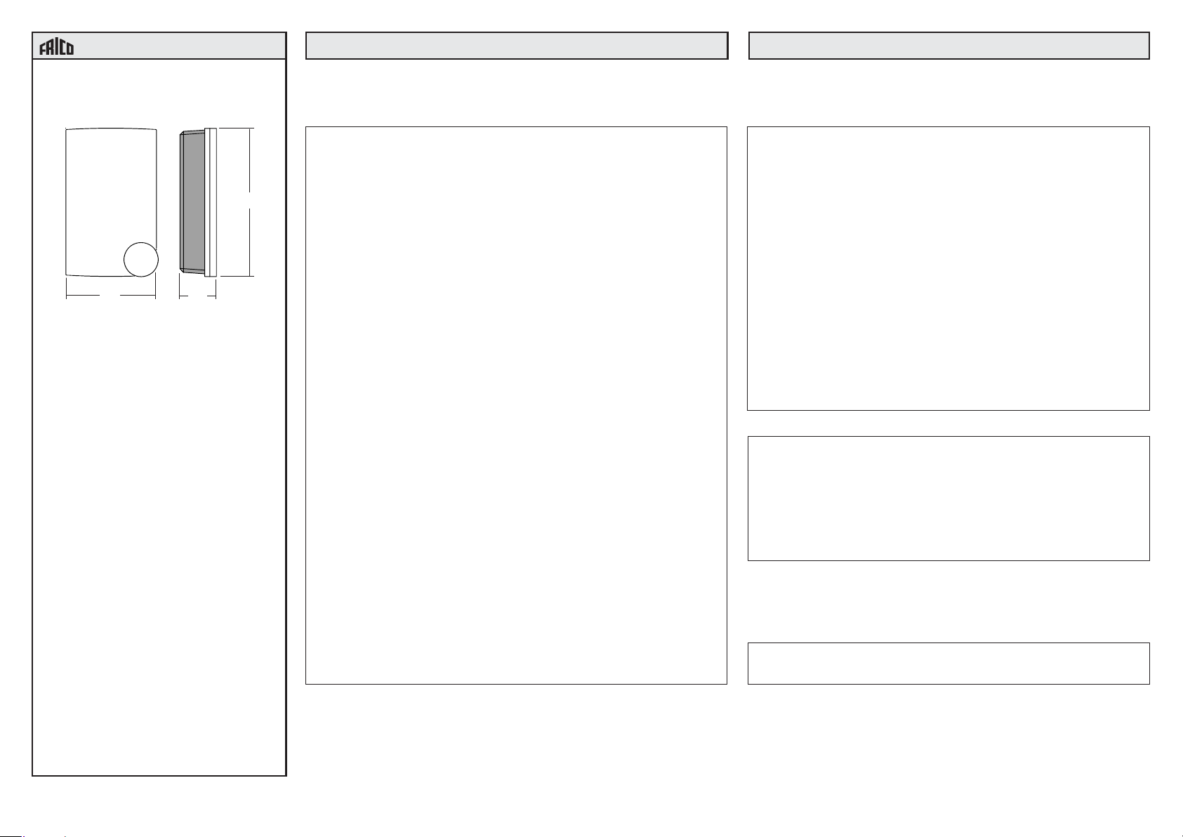
Montering
T ag av locket. Låsskruven finns bakom ratten. Montera ERP lodrätt med
kylflänsen uppåt.
Använd skruv med skalldiameter max 5.5mm.
Fästhålen har c:c 60mm för att ERP skall passa på eldosa.
Skall ERP användas med den inbyggda givaren monteras ERP
c:a 1.5m över golvet på plats med representativ temperatur. Luften
skall kunna cirkulera fritt kring apparaten utan att hindras av dörrar
eller möbler.
OBS: ERP avger c:a 20W förlustvärme som måste kunna kylas bort.
OBS: Max omgivningstemp vid max installerad effekt: +30°C.
Omgivningstemperatur: 0 - 30°C. Icke kondenserande.
Kapslingsklass: IP20.
NOV 98
Börvärdesbegränsning
Börvärdesinställningen kan mekaniskt begränsas med hjälp av
begränsningsskivorna bakom ratten.
Ställ börvärdesratten på ett värde inom det önskade intervallet.
Drag av ratten.
Lossa låsskruven som låser skivorna. Vrid den blå skivan så att
tappen hamnar strax nedanför den undre begränsningstemperaturen. Måtta med hjälp av markeringarna i botten på
lockets ratturtag. Markeringarna har 5° delning.
Ställ på motsvarande sätt den röda skivans tapp strax över den
övre begränsningstemperaturen.
Drag fast skruven utan att rubba skivornas läge.
Sätt på ratten igen och prova. Finjustera om nödvändigt.
ERP INSTRUKTION INSTRUKTION
153
93
Tillbehör
Beteckning E-nr
Kopplingsur ERPU 19 160 96
Ram, kopplingsur ERPR 85 815 39
Slavstyrd
elvärmeregulator ERPS 85 820 10
Golv/kanalgivare ERPGG 85 820 1 1
Rumsgivare ERPRG 85 820 12
40
Uppstart och felsökning
OBS: Var försiktig vid arbete i ERP. Samtliga komponenter inklusive
kylflänsen är spänningsförande. Lämna aldrig enheten
spänningssatt utan att locket är fastsatt.
1. Kontrollera att alla anslutningar är riktigt utförda och att givaromkopplarna står i rätt läge.
2. Mät resistansen mellan plintar 3 och 4: Vid 230V:
14.4Ω<R<230Ω. Vid 400V: 25Ω<R<400Ω.
3. Slå på matningsspänningen och vrid börvärdesratten till
maxläge. Lysdioden i sidan på ERP skall tändas alternativt
blinka med längre och längre tilltid för att till slut vara tänd kontinuerligt. Vrid ratten till minläget. L ysdioden skall släckas alternativt
blinka med kortare och kortare tilltid för att till slut vara kontinuerligt
släkt. I ett mellanläge (då ärvärdet = börvärdet) kommer lysdioden
att blinka i takt med att ERP pulsar fram ström. Pulscykeltiden är
c:a 60 sek.
Kontrollera med tångamperemeter att ström går ut till värmaren
då lysdioden är tänd.
Om något inte stämmer
4. Koppla loss kablar till eventuell yttre givare. Givarens resistans
varierar 15kΩ - 10kΩ mellan min- och max temperaturen i
arbetsområdet.
Resistansen ändrar sig 167Ω/°C.
5. Ställ givaromkopplarna bredvid plinten i läge för yttre givare (båda
skjutknapparna nedåt) men lämna givaranslutningarna G-G öppna.
Slå på matningsspänningen.
ERP skall ge full obruten effekt och lysdioden i sidan skall lysa.
Kontrollera med tångamperemeter att ström går ut till värmaren.
Om lysdioden är släckt och ingen ström går ut: Kontrollera att det
finns spänning fram till plintarna 1 och 2 och kontrollera
givaromkopplarnas läge igen. Om OK är det troligtvis fel i ERP .
Om lysdioden är tänd men ingen ström går ut: Kontrollmät
elbatteriets resistans enligt ovan. Om OK är det troligtvis fel i ERP.
6. Slå av matningsspänningen och kortslut mellan givaringångarna G-G men lämna givaromkopplarna i samma läge som
tidigare. Slå på matningsspänningen igen.
ERP skall inte ge någon uteffekt alls. Lysdioden skall vara
släckt. Kontrollera med tångamperemeter att ingen ström går
ut till värmaren.
Om lysdioden är släckt men ström går ut till värmaren:
Troligtvis fel i ERP.
Om lysdioden lyser: Kontrollera byglingen över G-G och att
givaromkopplarna är i sitt nedre läge. Om OK är det troligtvis
fel i ERP .
7. Om allt är rätt hit fram är ERP och givare OK.
Slå av matningsspänningen, tag bort kortslutningsbygeln från
G-G och koppla in eventuell yttre givare och/eller börvärdespotentiometer. S täll givaromkopplarna i rätt läge för det aktuella
driftsfallet enligt inkopplingsbilder na. Sätt på lock och ratt och
slå på matningsspänningen.
EMC emission och immunitet standard:
Produkten uppfyller kraven för gällande Europeiska EMC
standard CENELEC EN50081-1 och EN50082-1 och är
CE-märkt.
LVD, lågspänningsdirektivet:
Produkten uppfyller kraven för gällande Europeiska LVD
standard IEC 669-1 och IEC 669-2-1.
Teknisk hjälp
Hjälp och råd på telefon: 031-336 86 00
Frico AB
Box 102
433 22 Partille
Tel: 031-336 86 00
Fax: 031-26 28 25
mailbox@frico.se
www.frico.se
NOV 98

K
1
2 U
3 4
U
K G G
Fig 1: Wiring of supply voltage and
heater.
G
G
Fig 2: Switch setting for internal
sensor.
G
G
ERPGG
ERPRG
Fig 3: Switch setting and wiring for
and external sensor.
° C
K K
Fig 4: Wiring of night set-back
function.
Frico AB
Box 102
SE-433 22 Partille
Sweden
Tel: +46 31-336 86 00
Fax: +46 31-26 28 60
mailbox@frico.se
www.frico.se
INSTRUCTION INSTRUCTIONERP
T riac controller for proportional control
of electric heating
IMPORT ANT : Read these instructions before installation and wiring of
the product. Save this instruction in a safe place for future use.
!
ERP is a complete proportional controller for electric heating. It has
automatic voltage adjustment and can be used with either built-in
sensor or external sensor. ERP pulses the whole load On - Of f. The
ratio between On-time and Off-time is varied 0 - 100% to suit the
prevailing heat demand. The current is always switched at zero phase
angle to prevent RFI.
ERP is only intended for electric heating control. The control principle
makes it unsuitable for motor- or lighting control.
N.B. ERP cannot control 3-phase loads, as one phase is regulated.
Control principle
ERP pulses the full load On - Off. ERP adjusts the mean power
output to the prevailing power demand by proportionally adjusting
the ratio between On-time and Off-time. The pulse period (=the sum
of On-time and Off-time) is fixed 60 seconds.
ERP has zero phase-angle firing to eliminate RFI.
ERP automatically adjusts its control mode to suit the control object
dynamics.
For rapid temperature changes i. e. supply air control ERP will act
as a PI controller with a proportional band of 20K and a reset time
of 6 minutes.
For slow temperature changes i. e. room control ERP will act as a P
controller with a proportional band of 1.5K.
Assembly
Remove the front. The locking screw is be-hind the set-point knob.
Mount ERP vertically with the cooling flange at the top. Use screws
with a maximum head diameter of 5.5mm.
If ERP is to be used with the internal sensor, mount it approx. 5ft
above floor level at a location with a representative temperature.
The air must be able to circulate freely around the ERP without
disturbances from doors, furniture etc.
If ERP is to be used with external sensor it may be placed in any
location.
N.B. ERP emits approx. 20W of heat which must be dissipated.
N.B. Maximum ambient temperature at full load is 30°C.
Protection class: IP20.
NOV 98
Electrical installation
The installation, which should be proceeded by a fully isolating
switch with a contact gap of at least 3 mm, should be carried out
by a qualified technician and in accordance with applicable
directives.
Supply voltage (fig 1)
T erminals 1 and 2. Not polarity sensitive.
Supply voltage: 200 - 415V AC, 50 - 60 Hz with automatic voltage
adjustment.
Maximum current 16A.
Load (fig 1)
T erminals 3 and 4.
Resistive single- or two-phase heater
Maximum load: 3680W at 230V (16A)
6400W at 400V (16A)
Minimum load: 230W at 230V (1A)
400W at 400V (1A)
N.B. The cooling flange is live.
External sensor (figs 2 - 3)
T erminals G and G . Not polarity sensitive.
N.B. When using external sensor the equivalent function in the
ERP must be disabled. This is done by setting the DIPswitches to the right of the terminal strip according to the
figure 3.
N.B. The ERP sensors have high potential compared to neutral
and earth (>200V). Thus, wiring and installation of the
sensors must comply with local codes for line voltage
installations.
Night set-back (fig 4)
T erminal K and K.
Potential-free closure will give a night set-back of 0 - 10K. Settable
with a potentiometer in the ERP .
Setpoint range limiting
The setpoint range can be mechanically limited using the limiting
rings behind the setpoint knob.
Set the knob to a temperature within the desired limiting range.
Pull off the knob.
Loosen the screw locking the two rings. Rotate the blue ring so
that the protruding part is slightly lower than the lower temperature
limit. Use the markers on the bottom of the covers knob-cutout as
an aid. The markers are 5° apart.
In the same way set the red ring to a value slightly higher than the
upper limit temperature. Retighten the locking screw without
disturbing the position of the rings.
Replace the knob and check the result. Make fine adjustments if
necessary.
153
93
40
Accessoires
Code
Connection timer ERPU
Frame for connection timer ERPR
Slave controlled
electric heating regulator ERPS
Floor/duct sensor ERPGG
Room sensor ERPRG
INSTRUCTION INSTRUCTIONERP
Start-up and fault finding
N.B. Be careful when working in the ERP. All internal components
including the cooling flange are at line voltage potential.
Never leave the unit under power without the front cover on.
1. Check that all wiring is correct and that the sensor selector
switches are in the correct position.
2. Measure the resistance between terminals 3 and 4:
At 230V: 14.4Ω<R<230Ω. At 400V: 25Ω<R<400Ω.
3. Connect supply voltage and turn the setpoint knob to the
maximum value. The LED in the side of the ERP should be
continuously on or pulse on/off with longer and longer ontime
and eventually be continuously on.Turn the setpoint to the
minimum value. The LED in the side of the ERPshould be
continuously off or pulse on/off with longer and longer offtime
and eventually be continuously off. At a certain position (within
the proportional band) the LED will pulse On-Off as the ERP
pulses current to the heater The pulse cycle period is approx. 60
seconds. Check with a clamp-on ammeter that current is flowing
to the heater.
Something wrong?
4. Remove wiring to external sensor. The sensor resistance varies
between 10kΩ and 15kΩ between the upper and lower ends of the
sensor temperature range. The resistance changes by 167Ω/°C.
5. Set both the sensor selector switches in the downwards position
but leave the sensor inputs G-G open. Switch the voltage on.
ERP should give full uninterrupted power and the LED should be
lit. Check with a clamp-on ammeter that current is flowing to the
heater.
If the LED is not lit and no current is flowing: Check that you have
power on terminals 1 and 2 and recheck the positions of the
sensor selector switches. If OK the ERP is probably faulty .
If the LED lights up but no current is flowing: Recheck the heater
resistance as above. If OK the ERP is probably faulty .
6. Shut off power and short-circuit the sensor input G-G but leave
the switches in the downwards position. Switch on power
again.
ERP should not give out any power at all and the LED should
be extinguished. Check with a clamp-on ammeter that no
current is flowing to the heater.
If the LED is extinguished but current is flowing to the heater
the ERP is faulty .
If the LED is lit, recheck the shorting of terminals G-G. If OK
the ERP is faulty .
7. If everything OK this far the ERP and the sensor/setpoint are
OK.
Shut off power, remove the wire strap from G-G and reconnect
external sensor/setpoint if any. Set the sensor selector
switches in their correct positions according to the appropriate
wiring diagram for the installation at hand. Replace front cover
and setpoint knob. Connect power.
EMC emissions & immunity standards:
This product conforms with the requirements of
European EMC standards CENELEC EN 50081-1 and EN 500821 and carries the CE mark.
LVD
This product conforms with the requirements of
European LVD st andards IEC 669-1 and IEC 669-2-1.
Frico AB
Box 102
SE-433 22 Partille
Sweden
Tel: +46 31-336 86 00
Fax: +46 31-26 28 60
mailbox@frico.se
www.frico.se
NOV 98
 Loading...