

Page 1
Elektra V
.... 8 .... 10GB .... 12NO
SE
DE .... 21PL
.... 18
IT .... 28ES .... 25NL
.... 31
FR
FI .... 16RU
.... 14
.... 23
Page 2
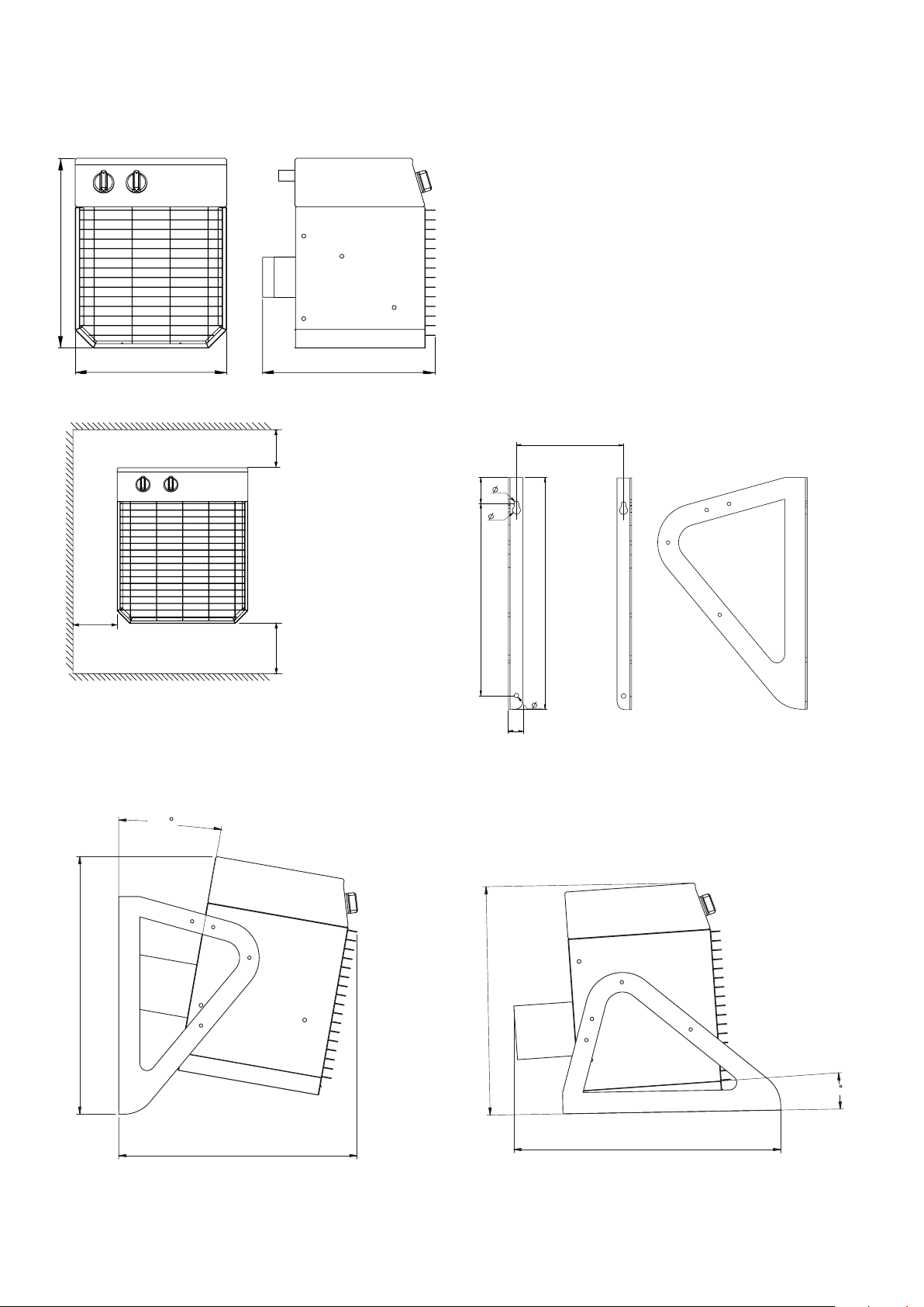
min 500 mm
min 300 mm
min
300 mm
ELV3333, ELV3344, ELV5333, ELV6344
380
300
375
10
419
412
415
415
3
9
16
24
333
375
9
28
c-c 277
Elektra V
Fig. 1
Fig. 2
Fig. 3
Fig. 4
2
Page 3
Elektra V
Fig. 5
Fig. 7
Fig. 6
Fig. 8
Technical specifications
Type Output
ELV331 3 0/2/3 230V~ 9.0/13.3 400 48 21 13
ELV3333 3 0/1.5/3 400V3~ 4.0/4.6 400 48 21 13
ELV3344 3,6 0/1.8/3.6 440V3~ 4.4/5.1 400 48 21 13
ELV5323 5 0/2.5/5 230V3~ 11.1/12,8 700 53 17 13
ELV5333 5 0/2.5/5 400V3~ 6.5/7.5 700 53 17 13
ELV6344 6 0/3/6 440V3~ 7.1/8.2 700 53 17 13
1
) Distance to fan: 5 metres.
2
) ∆t = Temperature rise of passing air at maximum heat output.
[kW]
Output
steps
[kW]
Voltage
[V]
Amperage
[A]
Airflow
[m3/h]
Sound
level*1
[dB(A)]
∆t
[°C]
*2
Weight
[kg]
3
Page 4
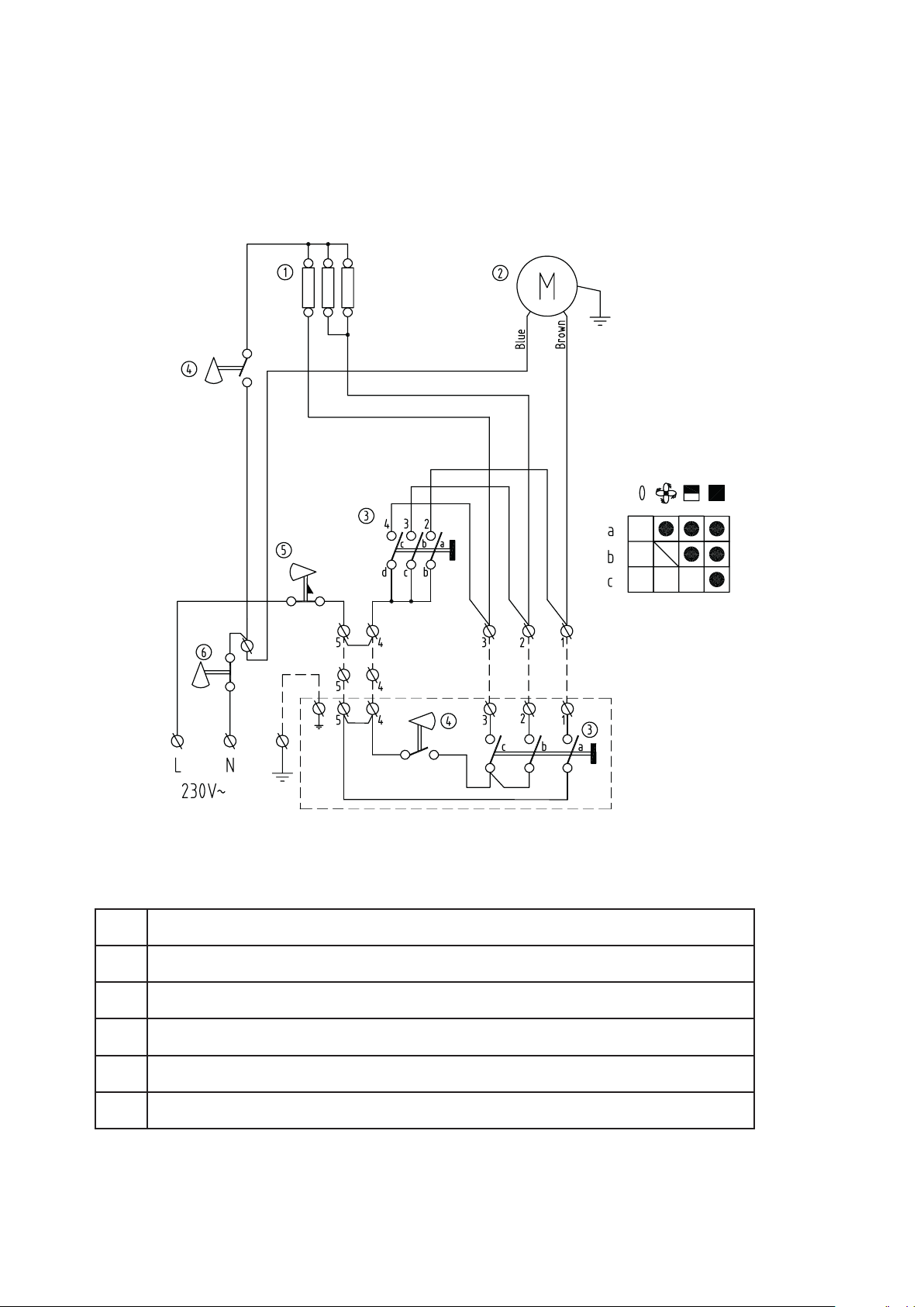
Elektra V 230V~
ELV331
ELV331
Elektra V
ELSRT
Element/Værmeelement/Element/Elementii/Element/Heizelement/
1
Verwarmingselement
Fläktmotor/Ventilator/Viftemotor/Puhallinmoottori/ Fan motor/
2
Gebläse motor/Moteur de ventilateur/Ventilatornotor
Brytare/Afbryder/Bryter/Katkaisin/Switch/Schalter/Interrupteur/
3
Schakelaar
Termostat/Termostat/Termostat/Termostaatti/Thermostat/Thermost/Thermostat/
4
Thermostaat
Överhettningsskydd/Overophedningsbeskytter/Overhetingsvern/Ylikuumenemissuoja/
5
Overheating cut-out/Überhitzungschutz/Protection contre la surchauffe/ Oververhittningsthermostaat
Överhettningsskydd/Overophedningsbeskytter/Overhetingsvern/Ylikuumenemissuoja/
6
Overheating cut-out/Überhitzungschutz/Protection contre la surchauffe/ Oververhittningsthermostaat
4
Page 5
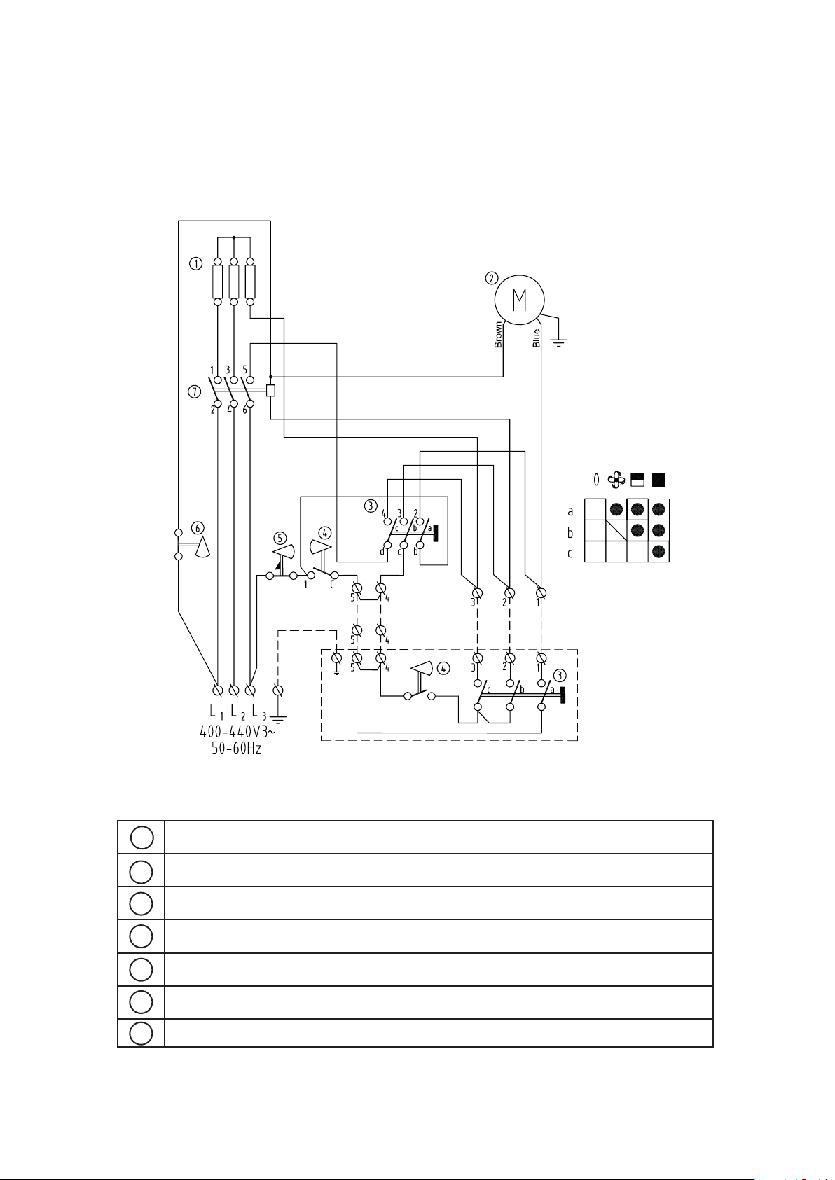
Elektra V 400/440V3~
ELV3333, ELV5333, ELV3344, ELV6344
ELV3333, ELV3344, ELV5333, ELV6344
Elektra V
ELSRT
Element/Værmeelement/Element/Elementii/Element/Heizelement/
1
Verwarmingselement
Fläktmotor/Ventilator/Viftemotor/Puhallinmoottori/ Fan motor/
2
Gebläse motor/Moteur de ventilateur/Ventilatornotor
Brytare/Afbryder/Bryter/Katkaisin/Switch/Schalter/Interrupteur/
3
Schakelaar
Termostat/Termostat/Termostat/Termostaatti/Thermostat/Thermost/Thermostat/
4
Thermostaat
Överhettningsskydd/Overophedningsbeskytter/Overhetingsvern/Ylikuumenemissuoja/
5
Overheating cut-out/Überhitzungschutz/Protection contre la surchauffe/ Oververhittningsthermostaat
Överhettningsskydd/Overophedningsbeskytter/Overhetingsvern/Ylikuumenemissuoja/
6
Overheating cut-out/Überhitzungschutz/Protection contre la surchauffe/ Oververhittningsthermostaat
Kontaktor/Kontaktor/Kontaktor/Kontaktori/Contactor/Schutz/Contacteur/Relais
7
5
Page 6
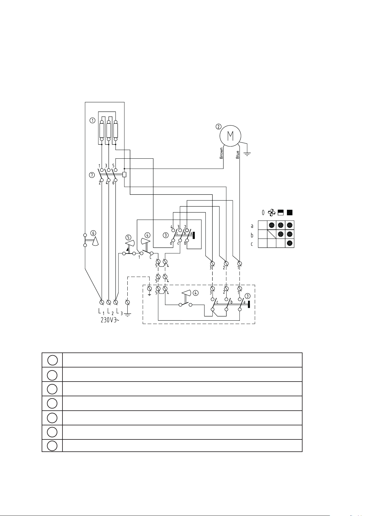
Elektra V 230V3~
ELV5323
ELV5323
Elektra V
ELSRT
Element/Værmeelement/Element/Elementii/Element/Heizelement/
1
Verwarmingselement
Fläktmotor/Ventilator/Viftemotor/Puhallinmoottori/ Fan motor/
2
Gebläse motor/Moteur de ventilateur/Ventilatornotor
Brytare/Afbryder/Bryter/Katkaisin/Switch/Schalter/Interrupteur/
3
Schakelaar
Termostat/Termostat/Termostat/Termostaatti/Thermostat/Thermost/Thermostat/
4
Thermostaat
Överhettningsskydd/Overophedningsbeskytter/Overhetingsvern/Ylikuumenemissuoja/
5
Overheating cut-out/Überhitzungschutz/Protection contre la surchauffe/ Oververhittningsthermostaat
Överhettningsskydd/Overophedningsbeskytter/Overhetingsvern/Ylikuumenemissuoja/
6
Overheating cut-out/Überhitzungschutz/Protection contre la surchauffe/ Oververhittningsthermostaat
Kontaktor/Kontaktor/Kontaktor/Kontaktori/Contactor/Schutz/Contacteur/Relais
7
6
Page 7
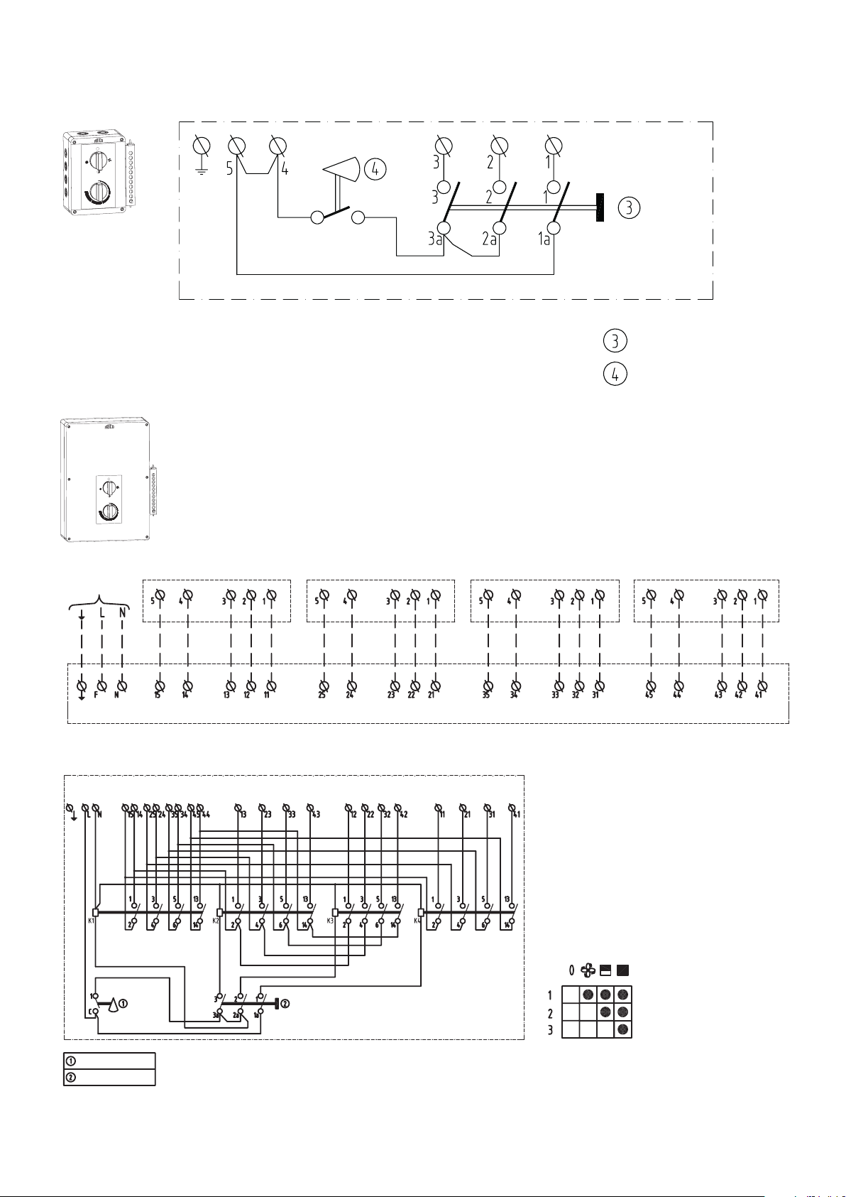
ELSRT
Switch
Thermostat
ELC/V 3-9 kW ELC/V 3-9 kW
ELC/V 3-9 kW
ELC/V 3-9 kW
ELSRT4
Elektra V
ELSRT
Switch
Thermostat
230V~
ELSRT4
ELSRT4
Thermostat
Switch
7
Page 8
GB
Elektra V
Mounting and assembly instruction
Application area
The fan heater is approved for use on ships and
off-shore applications. Elektra V has reinforced
electrical insulation, motor and heating elements
have a construction that absorbs vibrations. For
both fixed installation and portable use. Elektra
V is available in 230V~, 400V3~ and 50 Hz and
440V3~ and 60Hz.
The fan heater should be installed for easy
maintenance and inspection. For portable use,
mount a suitable terminal with appropriate
protection class. The fan heater is tested and
approved according to the EMC- and SEMKO
regulations and is CE compliant. Protection class:
IP44. Approved by DNV, Det norske Veritas. The
heater is also approved for 440V3~ and 60Hz.
Casing and heating rods are made of stainless
steel SS2320.
Operation
The fan is running constantly unless the output
selector is set in 0 position. The heat output is
controlled by the built in thermostat (0- +35°C) or
with an external thermostat (KRT1900).
The on/off mode, and half or full heat output
can be controlled with the output selector on the
unit or with an external control panel (ELSRT/
ELSRT4) mounted on the wall for easy access.
External control box or thermostat are ordered
separately.
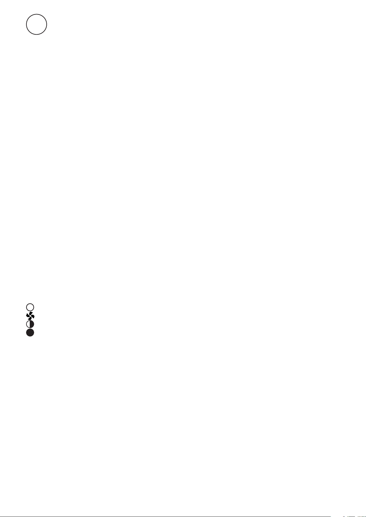
Off
Only fan
Fan + half output
Fan + full output
Mounting
Elektra V can be mounted permanently on the
wall or be used as a portable fan heater.
Wall mounting
The fan heater must not be placed immediately
below or in front of a wall socket.
Remove the plastic feet on the brackets.
1.Drill four holes in the wall with a c-c distance
according to fig. 2 on page 2.
2.Fit the screws in the upper two holes.
3.Hang the heater by using the keyholes in the
bracket and lock with the two lower screws.
Note! The minimum distances according to fig. 1
on page 2.
Portable use
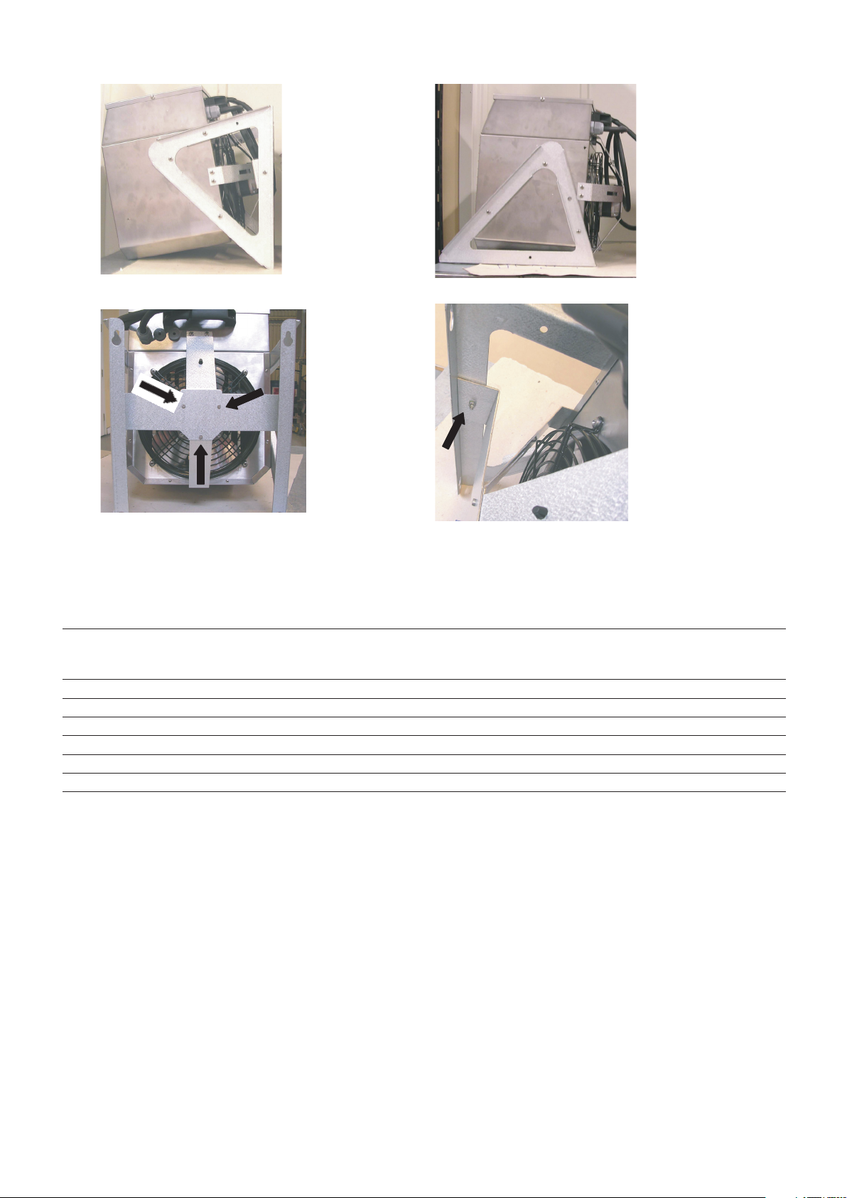
1.Loosen the three screws with washers from the
motor, see Fig. 7 page 3.
2.Loosen the screws on the bracket (the bracket
is fitted on the casing).
3.Then loosen the two screws connecting the
bracket and the support, see Fig. 8 page 3.
4.The support between motor and bracket is
removed, it is not needed for portable use.
5.Fasten the three screws to the motor, see Fig. 7
page 3. Note! Don’t forget the washers.
6.Mount the brackets on the fan according to
Fig. 6 page 3.
Electrical installation
The electrical installation should be carried out
by a qualified electrician in conformity with
prevailing regulations. The appliance should be
preceded by an all-pole switch with at least 3 mm
breaking gap.
Use the knock-outs on the back of the appliance
for installation of the external devices. Cableglands used must guarantee the protection class
requirements.
Overheating
Note! Opening the heater cover should only be
done by a qualified installer.
The heater is equipped with two overheat
protections, one with manual reset and one with
automatic reset. If the manual overheat protection
is released due to overheating, reset as follows:
• Disconnect the power with the fully isolated
switch.
• Investigate the matter and repair the fault.
• Reset cut-out by opening the lid and pressing
the red button until a click is heard.
• Put on the lid and make sure that the screws are
tightened to ensure full protection. If the fault
continues or cannot be fixed, please contact a
qualified technician.
Maintenance
Note! Opening the heater cover should only be
done by a qualified installer.
Always disconnect the power supply before
opening the cover or doing any maintenance
work.
The appliance should be cleaned regularly both
inside and outside, to prevent overheating and
10
Page 9
Elektra V
GB
risk of fire but also to guarantee long life of the
heater.
Note! To keep the protection class it is very
important to tighten the screws properly when
the lid is put back again after installation or
maintenance.
Packaging
Packaging materials are chosen with consideration
to environment and are therefore recyclable.
Handling of product at end of working life
Tthis product may contain substances necessary
for functionality of product but potentially
dangerous for the environment. The product
should not be disposed mixed with general
household waste but delivered to a designated
collection point for environmental recycling.
Please contact local authority for further details of
your nearest designated collection point.
Safety instructions
Incorrect installation and/or incorrect usage of the
fan heater can be hazardous.
aged from 8 years and above and persons
with reduced physical, sensory or mental
capabilities or lack of experience and
knowledge if they have been given supervision
or instruction concerning use of the appliance
in a safe way and understand the hazards
involved. Children shall not play with the
appliance. Cleaning and user maintenance
shall not be made by children without
supervision.
• Children of less than 3 years should be kept
away unless continuously supervised.
• Children aged from 3 years and less than 8
years shall only switch on/off the appliance
provided that it has been placed or installed
in its intended normal operating position
and they have been given supervision or
instruction concerning use of the appliance
in a safe way and understand the hazards
involved.
• Children aged from 3 years and less than 8
years shall not plug in, regulate and clean the
appliance or perform user maintenance.
Warning!
• Always disconnect the fan heater berfore
opening the cover or doing any electrical
work.
• Incorrect installation can lead to personal
injury.
• Opening the heater cover etc should only be
done by a qualified installer
• This fan heater must not be used next to a
shower, bath or swimming pool.
• Place the fan heater away from flammable
materials
• Ensure that the area around the intake and
exhaust grille is kept free from material
which could obstruct the air flow through
the unit!
• The unit must not be covered fully or
partially with clothes, or similar materials,
as overheating can result in a fire risk!
• The fan heater is fitted with a cable that, in
the event of damage, must be changed by a
qualified installer.
• This appliance can be used by children
CAUTION — Some parts of this product can
become very hot and cause burns. Particular
attention has to be given where children and
vulnerable people are present.
Important!
When using the heater as a portable, the brackets
must be turned in order to use them as a floor
stand (see fig 4 on page 3).
The guarantee is only valid if the units are used in
the manner intended by the manufacturer and in
accordance with the installation and maintenance
instructions.
Accessories
For fixed installation the heater can be controlled
by an external control panel with a built in
thermostat 0 – +35°C. It is also possible to use
only an external thermostat to control the heat
output. The ELSRT can only control one unit. For
parallel connection of up to 4 units the ELSRT4
can be used. When ELSRT is being used, the builtin thermostat must be set to max and the output
selector on the unit to Off
See table below.
.
Type Description HxWxD
[mm]
ELSRT Control panel and thermostat, controls one fan heater, IP65 175x150x100
ELSRT4 Control panel and thermostat (not ELC1533), controls 4 fan heaters, IP65 255x360x110
11
Page 10
Main offi ce
Frico AB Tel: +46 31 336 86 00
Industrivägen 41
SE-433 61 Sävedalen [email protected]
Sweden www.frico.net
For latest updated information and information
about your local contact: www.frico.net.
2020-02-13 HH/CH
 Loading...