

Page 1
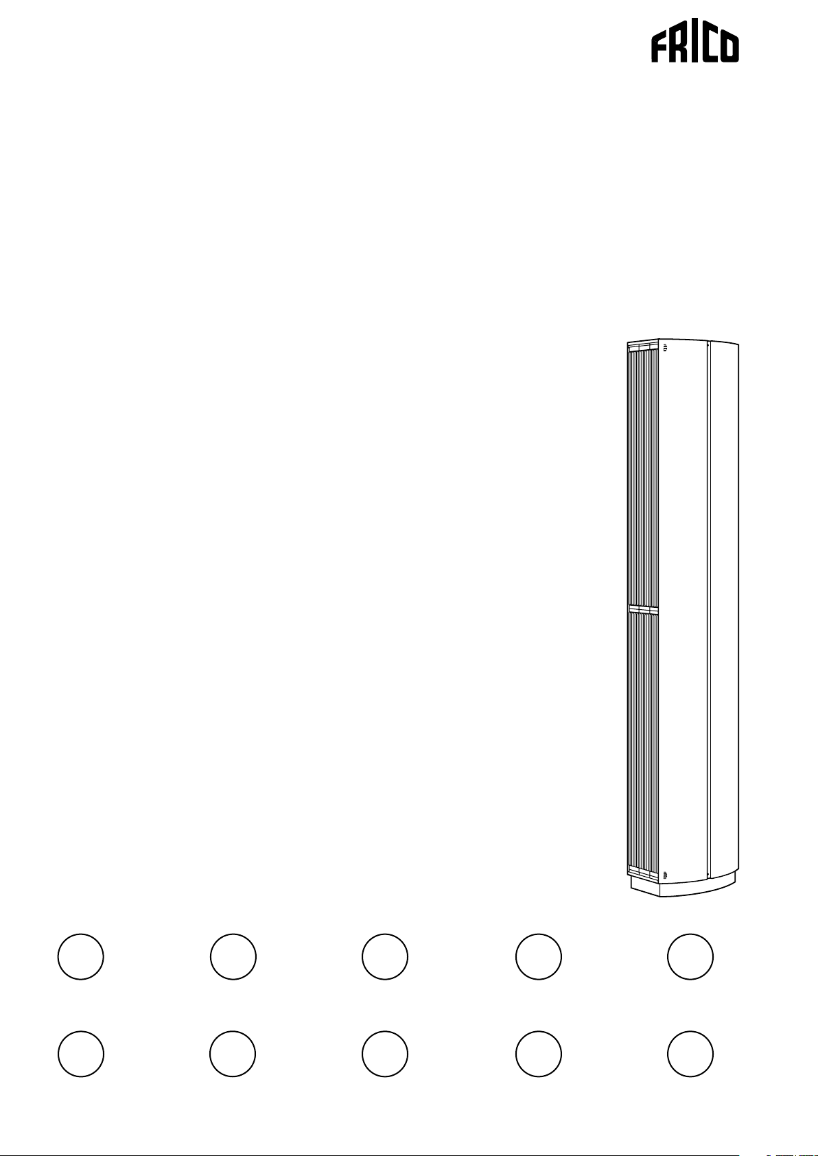
Thermozone AC Corinte
SE
FI
.... 16
.... 36
GB
NL
.... 19
.... 40
DE
NO
.... 24
.... 44
FR
PL
.... 28
.... 48
ES
RU
.... 32
.... 52
Page 2
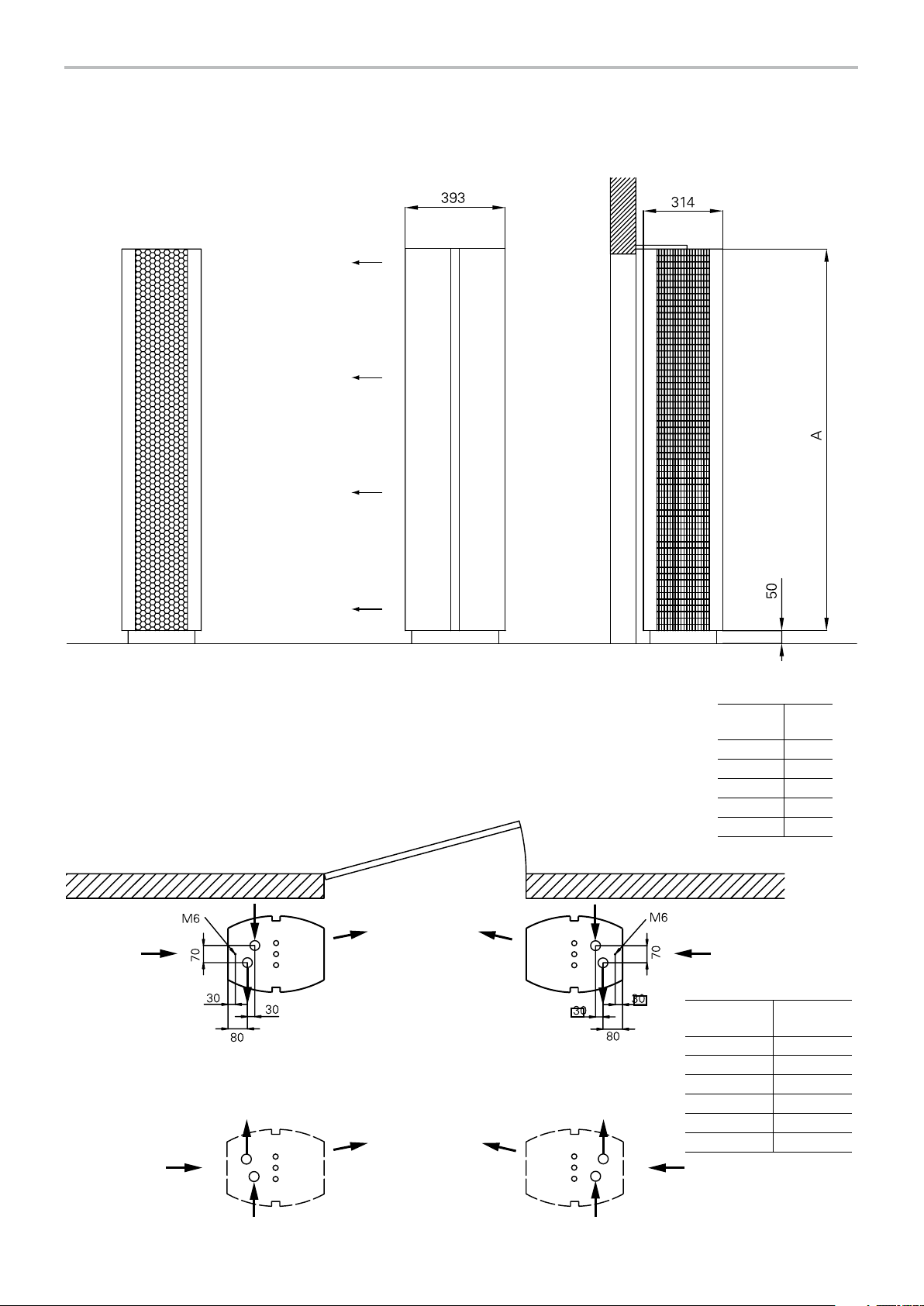
Dimensions and connections
Vertical ACC E/W
AC Corinte
Details of ACC W
Intake
Doorway
Outlet
Upper part
of the unit
seen from
above.
Bottom part
of the unit
seen from
above.
A
[mm]
ACC10 1000
ACC15 1500
ACC20 2000
ACC25 2500
ACC30 3000
Connection dimensions,
inside thread
3/4”
Ø
ACC WL X
ACC10WH X
ACC15WH X
ACC20WH X
ACC25WH X
ACC30WH X
DN20
1”
DN25
2
Page 3

AC Corinte
Dimensions and connections
Details of ACC W
120
50
Horizontal ACC E/W
3
Page 4
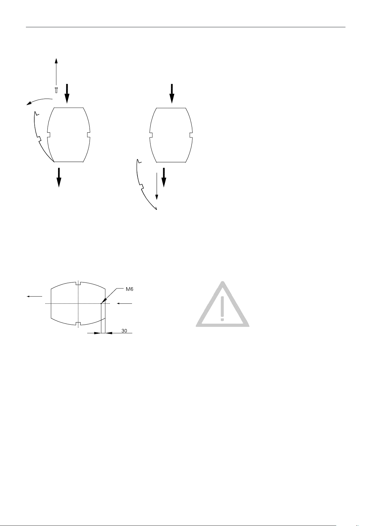
To open
AC Corinte
Fig. 1: To open
Mounting
Fig. 2: Securing in the wall or ceiling.
Note! The air curtain
must be secured in
the wall or ceiling.
4
Page 5
AC Corinte
35
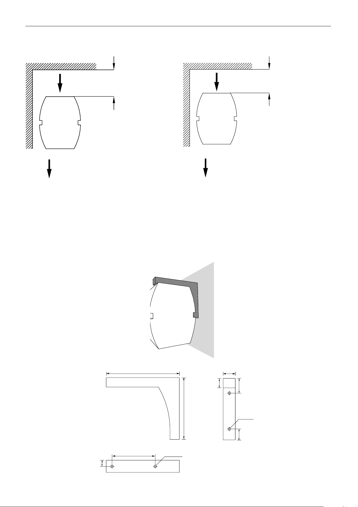
Minimum distance
200
Fig. 3 Minimum distance, ACC E. Fig. 4 Minimum distance, ACC W.
ACC Wallbracket
180
31
185
26
Ø8 M8 (2x)
264
2
40
50 39
Ø12 (2x)
5
Page 6

Accessories - AC Corinte E/W
Type Description
CK01E Control kit Electric level 1 (CB32N, RTI2)
CK02E Control kit Electric level 2 (CB32N, RTI2,
MDC)
CK03GD Control kit level 3 (ADEA, ADEAIS, ADEAEB,
ADEAGD1)
CK01W Control kit Water level 1 (CB30N, T10)
CK02W Control kit Water level 2 (CB30N, RTI2, MDC)
CB30N Control box (A/W)
CB32N Control box (E)
ADEA Air curtain control
ADEAEB External control board, IP55
ADEAIS External room sensor, IP30
ADEAGD1 Additional control board to acheive ADEA
and BMS functionality
RTI2 2-step room thermostat, IP44
RTI2V 2-step room thermostat, knob, IP44
T10 Room thermostat, IP30
KRT1900 Room thermostat, IP55
MDC Magnetic door contact with time relay, IP44
AGB304 Door contact, IP44
KUR Digital time switch, IP55
CBT Electronic timer, IP44
VR20 Valve set, DN 20 mm
VR25 Valve set, DN 25 mm
TVV20 2-way control valve, DN 20 mm
TVV25 2-way control valve, DN 25 mm
SD20 Actuator
ACCWBP Wall bracket polished bright annealed*
ACCWBB Wall bracket brushed stainless steel*
ACCWBMP Wall bracket mirror polished stainless steel*
AXP300 Collision protection
*) For ACC 1-1,5 m: order 2 pcs, for ACC 2-3 m: order 3 pcs.
More information about accessories on pages 29-31 and 60-62.
AC Corinte
6
Page 7
AC Corinte
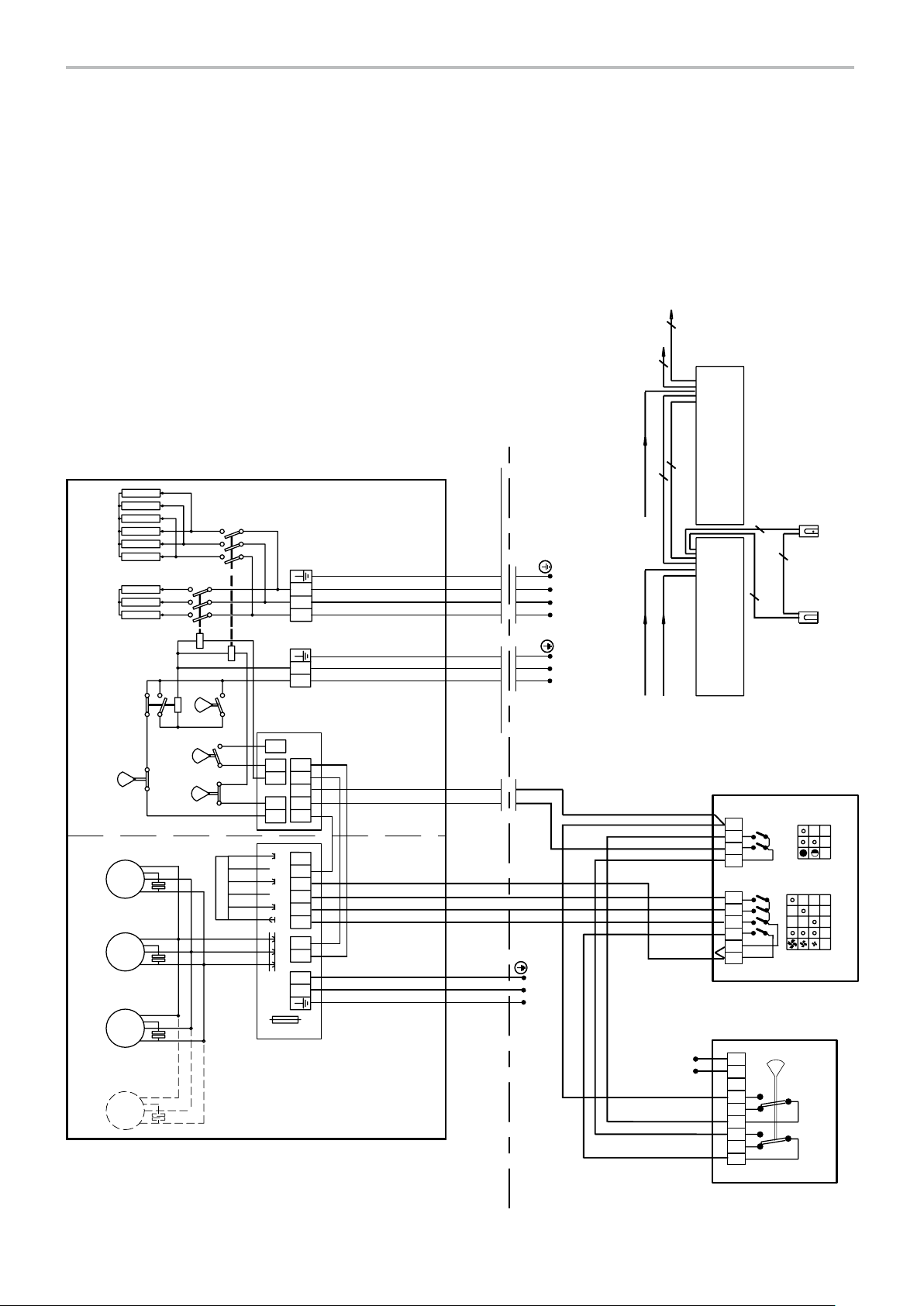
Wiring diagrams AC Corinte
Electric regulations options
Level 1
2+PE
I + II = III
III
K2
K1
C
C
F3
50º
C
~
M
1
~
11
~
MM
C
K3
F2
F4
F5
Trafo
6x0,5mm² 4x0,5mm²
2×(2+PE)
AC Corinte E
6x0,5mm²
CB32N
LLL
123
2+PE
4x0,5mm²
RTI2
LN
80º
78
6
5
3
N123456
L
C3
C2
C7
C6
C1
50º
40º
230V
200V
170V
140V
120V
LNPE L1 L2L3 PEC6 C7
control
Supply heat
230V~ 400V3~
400V3~ Heat 400V3~ Heat
2×230V~ Motor and control
AC Corinte E
10
789
234561
0 0
CB32N
230V~
Fuse
~
M
1
Thermozone AC Corinte E
Supply fan Supply heater
230V~
C°
234567LN1
Hi Lo
RTI2
7
Page 8
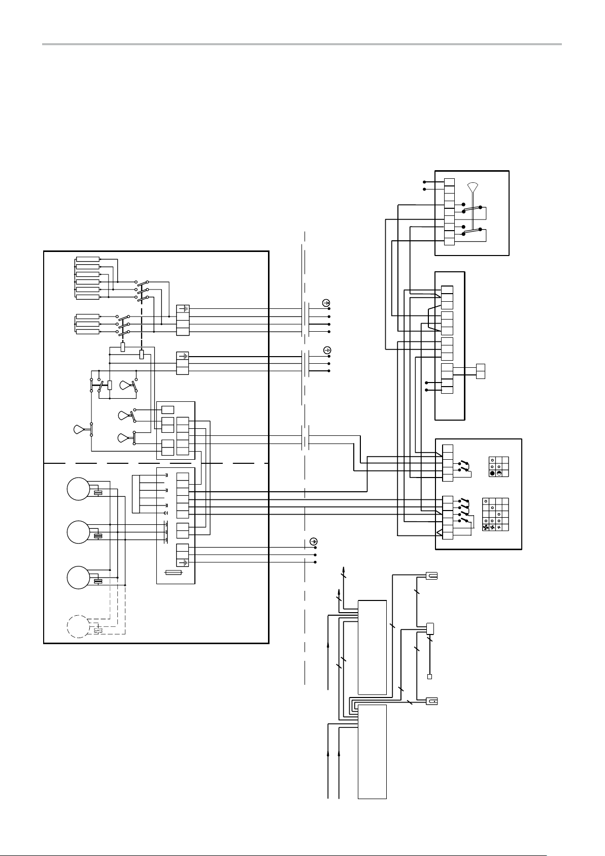
Wiring diagrams AC Corinte
Electric regulations options
Level 2
AC Corinte
I + II = III
III
M
230V~
C°
234567LN1
Hi Lo
RTI2
Supply heater
LLL
123
K2
K3
LN
K1
F2
80º
C
LNPE L1 L2L3 PEC6 C7
230V~ 400V3~
32
31 34
22
21 24
12
11 14
DC DC
NL
Door
contact
control
230V~
53 6 78
C3
C2
C7
C6
C1
Supply heat
F4
50º
C
F3
50º
C
~
1
F5
40º
C
230V
200V
170V
140V
Trafo
120V
MDC
10 11
789
~
11
~
MM
~
M
1
Thermozone AC Corinte E
Fuse
N 123456
L
234561
0 0
CB32N
230V~
RTI2
Supply fan
2+PE
2+PE
MDC
2x0,5mm²
Door
contact
6x0,5mm² 6x0,5mm²
2×(2+PE)
AC Corinte E
5x0,5mm² 4x0,5mm²
2+PE
CB32N
6x0,5mm²
400V3~ Heat 400V3~ Heat
AC Corinte E
230V~ Motor and control
8
Page 9

ADEAEB +
ADEAGD1
ADEAR
MDCDC
2x0,5mm²
AC Corinte
Wiring diagrams AC Corinte
Electric regulations options
Level 3
2+PE
I + II = III
III
K1
F3
50º
˚C
~
M
1
~
11
~
MM
~
M
1
Thermozone AC Corinte E
Supply heaterSupply fan
10x0,5mm² 10x0,5mm²
AC Corinte E
2×(2+PE)
LLL
123
1
2
ADEAOS
ADEAIS
2+PE
K2
K3
Supply heat
C
C
C
C
C
Control
!
LNPE L1 L2 L3 PE
control
3
2
7
6
1
heat
230V~
230V~
230V~ 400V3~
51 8180 8382 84 8685 87 G2G1 G4G3 G5 C2C1 C3 C6 C7
50
41
31
30 40
21
20
11
89
6
5
LN4
ADEAGD1
400V3~ Heat 400V3~ Heat
2×230V~ Motor and control
11
10
9
8
7
6
5
4
AC Corinte E
ADEAR
LN
F2
80º
˚C
F4
50º
˚C
F5
40º
˚C
230V
200V
170V
140V
Trafo
120V
78
6
5
3
Fuse
78
6
5
3
C3
C2
C7
C6
C1
N 123456
L
C3
C2
C7
C6
C1
8x0,5mm²
10x0,5mm²
2x0,5mm²
2x0,5mm²
ADEAIS
4
MDCDC
ADEAOS
Fuse
ADEAEB
N 123456
L
9
Page 10

Wiring diagrams AC Corinte
Water regulations options
Level 1
2+PE
2+PE
4x0,5mm² 4x0,5mm²
AC Corinte W
AC Corinte
4x0,5mm²
CB30N
2+PE
Thermozone AC Corinte W
M
M
M
T10
2+PE
SD20
AC Corinte W
230V~ Motor and control
7N
B3
B2
6
Fuse
LN 1 2345
Control
1234
LNPE
Supply fan
230V~
230V~
2345671
0
CB30N
230V
1~
1~
1~
200V
170V
140V
Trafo
120V
10
SD20
TVV20/25
A/B
2
2
7
6
4
4
>t°C
T10
Page 11

AC Corinte
Wiring diagrams AC Corinte
Water regulations options
Level 2
2+PE
2+PE
4x0,5mm² 4x0,5mm²
AC Corinte W
4x0,5mm²
CB30N
Thermozone AC Corinte W
M
M
M
1~
1~
1~
2+PE2+PE
3x0,5mm²
MDC
AC Corinte W
230V~ Motor and control
2x0,5mm²
2x0,5mm²2+PE
Door
contact
RTI2SD20
7N
230V
200V
170V
B3
140V
Trafo
120V
Fuse
B2
LN123456
Control
1234
LNPE
Supply fan
230V~
22
21 24
12
11 14
2345671
0
CB30N
230V~
DC DC
LN
MDC
Door
contact
SD20
234567NL1
TVV20/25
C°
Hi Lo
RTI2
11
Page 12

Wiring diagrams AC Corinte
4
MDCDC
Water regulations options
Level 3
7N
AC Corinte
Thermozone AC Corinte W
M
M
M
1~
1~
1~
Trafo
2+PE
230V
200V
170V
140V
120V
6
B3
B2
LN 1 2345
Fuse
SD20
51234
LNPE
Supply fan
ADEAR
230V~
G4
G3 G5
G2G1
83
82 84 8685 87
51 8180
50
41
40
31
30
21
20
11
89
6
5
ADEAGD1
11
10
9
8
7
6
5
4
ADEAR
1
2
12
2+PE
5x0,5mm² 5x0,5mm²
AC Corinte W
5x0,5mm²
2+PE
230V~ Motor and control
AC Corinte W
8x0,5mm²
2+PE
2x0,5mm²
2x0,5mm²
ADEAIS
ADEAOS
230V~
ADEAGD1
ADEAEB +
2x0,5mm²
MDCDC
LN4
ADEAEB
SD20
ADEAOS
ADEAIS
TVV20/25
Page 13

AC Corinte
Output charts water
AC Corinte WL
Incoming water: 80°C Incoming / outgoing water temperature 80/60°C
Incoming air temp. +18°C Incoming air temp. = +15°C Incoming air temp. = +20°C
Outgoing air temp. +33 °C
Type Fan
position
ACC10WL max 190 0 9,6 0,05 31 19,7 46 0,24 1 7, 8 48 0,22
min 950 4,9 0,03 33 12,1 53 0,15 10,9 54 0,13
ACC15WL max 2600 13,1 0,06 27 29,6 49 0,36 26,7 51 0,33
min 1350 6,8 0,03 26 18,5 56 0,23 16,7 57 0,21
ACC20WL max 3800 19,1 0,09 27 42,7 48 0,52 38,9 50 0,47
min 1980 10,2 0,05 27 26,8 55 0,33 24,3 56 0,30
ACC25WL max 4500 22,7 0,10 27 51,9 49 0,63 47,1 51 0,58
min 2340 11,7 0,06 28 32,3 56 0,39 29,3 57 0,36
ACC30WL max 510 0 25,8 0.12 27 60,2 50 0,74 54,5 52 0,67
min 2660 10,6 0,05 29 37,4 57 0,46 33,9 58 0,41
Airflow
3
[m
/h]
Output
[kW]
Water
flow
[l/s]
Return
water
[°C]
Output
[kW]
Outgoing
air temp.
[°C]
Water
flow
[l/s]
Output
[kW]
Outgoing
air temp.
[°C]
Water
flow
[l/s]
Incoming water: 60°C Incoming / outgoing water temperature 60/50°C
Incoming air temp. +18°C Incoming air temp. = +15°C Incoming air temp. = +20°C
Outgoing air temp. +33 °C
Type Fan
position
ACC10WL max 190 0 9,6 0,10 37 14,5 38 0,35 12,7 40 0,31
min 950 4,8 0,04 32 8,9 43 0,22 7, 7 44 0,19
ACC15WL max 2600 13,1 0,11 32 21,7 40 0,53 18,9 42 0,46
min 1350 6,8 0,05 28 13,5 45 0,33 11,8 46 0,29
ACC20WL max 3800 19,2 0,17 33 31,3 40 0,76 27,3 41 0,66
min 1980 10,0 0,08 28 19,6 44 0,48 1 7, 1 46 0,41
ACC25WL max 4500 22,7 0,20 32 38,0 40 0,92 33,2 42 0,81
min 2340 11,8 0,09 29 23,6 45 0,58 20,7 46 0,50
ACC30WL max 510 0 25,7 0,22 32 44,1 41 1,07 38,5 42 0,93
min 2660 13,6 0,11 29 27,4 46 0,66 23,9 47 0,58
Type Fan
position
ACC10WL max 1900 9,6 0,10 37 11,8 33 0,14 9,9 35 0,12
min 950 4,8 0,04 32 7, 3 38 0,09 6,2 39 0,08
ACC15WL max 2600 13,1 0,11 32 18,1 36 0,22 15,3 38 0,19
min 1350 6,8 0,05 28 11,3 39 0,14 9,6 41 0,12
ACC20WL max 3800 19,2 0,17 33 26,1 35 0,32 22,0 37 0,27
min 1980 10,0 0,08 28 16,4 40 0,20 13,9 41 0,17
ACC25WL max 4500 22,7 0,20 32 31,8 36 0,39 26,7 38 0,32
min 2340 11,8 0,09 29 19,8 40 0,24 16,7 41 0,20
ACC30WL max 510 0 25,7 0,22 32 36,8 37 0,45 31,0 38 0,38
min 2660 13,6 0,11 29 22,9 41 0,28 19,4 42 0,23
Airflow
3
[m
/h]
Airflow
3
[m
/h]
Output
[kW]
Incoming water: 60°C Incoming / outgoing water temperature 60/40°C
Incoming air temp. +18°C Incoming air temp. = +15°C Incoming air temp. = +20°C
Outgoing air temp. +33 °C
Output
[kW]
Water
flow
[l/s]
Water
flow
[l/s]
Return
water
[°C]
Return
water
[°C]
Output
[kW]
Output
[kW]
Outgoing
air temp.
[°C]
Outgoing
air temp.
[°C]
Water
flow
[l/s]
Water
flow
[l/s]
Output
[kW]
Output
[kW]
Outgoing
air temp.
[°C]
Outgoing
air temp.
[°C]
Water
flow
[l/s]
Water
flow
[l/s]
13
Page 14

AC Corinte
Incoming water: 60°C Incoming / outgoing water temperature 60/30°C
Incoming air temp. +18°C Incoming air temp. = +15°C Incoming air temp. = +20°C
Outgoing air temp. +33 °C
Type Fan
position
ACC10WL max 1900 9,6 36,6 0,10 8,7 29 0,07 6,4 30 0,05
min 950 4,8 32,3 0,04 4,9 30 0,04 2,8 29 0,02
ACC15WL max 2600 13,1 32,4 0,11 13,8 31 0,11 10,7 32 0,09
min 1350 6,8 27,8 0,05 8,9 35 0,07 6,9 35 0,06
ACC20WL max 3800 19,2 33,0 0,17 19,9 31 0,16 15,3 32 0,12
min 1980 10,0 28,3 0,08 12,8 34 0,10 9,8 35 0,08
ACC25WL max 4500 22,65 32,1 0,20 24,1 31 0,19 18,6 32 0,15
min 2340 11,8 28,6 0,09 15,4 35 0,13 11,3 34 0,08
ACC30WL max 5100 25,7 32,5 0,22 28,0 31 0,23 21,7 33 0,18
min 2660 13,6 29,0 0,11 1 7, 8 35 0,14 12,2 34 0,10
Output charts water
AC Corinte WH
Type Fan
position
ACC10WH max 190 0 9,6 0,03 46 15,4 39 0,06 14,3 42 0,06
min 950 4,8 0,10 50 10,4 47 0,04 9,7 50 0,04
ACC15WH max 2600 13,1 0,03 35 24,8 43 0,10 23,2 47 0,09
min 1350 6,8 0,02 37 16,7 52 0,07 15,6 54 0,06
ACC20WH max 3800 19,2 0,05 36 35,6 43 0,15 33,1 46 0,14
min 1980 11,1 0,03 38 24,1 51 0,10 22,5 54 0,09
ACC25WH max 4500 22,8 0,06 37 43,6 44 0,18 40,6 47 0,17
min 2340 14,5 0,04 41 23,9 52 0,12 27,3 55 0,11
ACC30WH max 510 0 25,8 0,07 37 50,9 45 0,21 47,5 48 0,20
min 2660 1 7, 8 0,05 42 34,3 53 0,14 32,0 56 0,13
Airflow
3
[m
/h]
Airflow
3
[m
/h]
Output
[kW]
Incoming water: 130°C Incoming / outgoing water temperature 130/70°C
Incoming air temp. +18°C Incoming air temp. = +15°C Incoming air temp. = +20°C
Outgoing air temp. +33 °C
Output
[kW]
Water
flow
[l/s]
Water
flow
[l/s]
Return
water
[°C]
Return
water
[°C]
Output
[kW]
Output
[kW]
Outgoing
air temp.
[°C]
Outgoing
air temp.
[°C]
Water
flow
[l/s]
Water
flow
[l/s]
Output
[kW]
Output
[kW]
Outgoing
air temp.
[°C]
Outgoing
air temp.
[°C]
Water
flow
[l/s]
Water
flow
[l/s]
Incoming water: 110°C Incoming / outgoing water temperature 110/80°C
Incoming air temp. +18°C Incoming air temp. = +15°C Incoming air temp. = +20°C
Outgoing air temp. +33 °C
Type Fan
position
ACC10WH max 190 0 9,6 0,04 48 16,1 40 0,13 15,1 44 0,13
min 950 4,8 0,02 49 10,8 49 0,09 10,0 51 0,08
ACC15WH max 2600 13,1 0,04 39 25,3 44 0,21 23,6 47 0,19
min 1350 6,8 0,02 37 16,9 52 0,14 15,8 55 0,13
ACC20WH max 3800 19,1 0,07 40 36,3 43 0,30 39,9 47 0,28
min 1980 10,0 0,03 38 24,5 52 0,20 22,8 54 0,19
ACC25WH max 4500 22,7 0,08 39 44,5 44 0,37 41,6 47 0,34
min 2340 12,7 0,04 40 29,8 53 0,24 27,8 55 0,23
ACC30WH max 5 100 25,7 0,09 38 52,0 45 0,43 48,6 48 0,40
min 2660 10,7 0,04 41 34,7 54 0,29 32,4 56 0,27
Airflow
3
[m
/h]
Output
[kW]
Water
flow
[l/s]
Return
water
[°C]
Output
[kW]
Outgoing
air temp.
[°C]
Water
flow
[l/s]
Output
[kW]
Outgoing
air temp.
[°C]
14
Water
flow
[l/s]
Page 15

AC Corinte
Incoming water: 90°C Incoming / outgoing water temperature 90/70°C
Incoming air temp. +18°C Incoming air temp. = +15°C Incoming air temp. = +20°C
Outgoing air temp. +33 °C
Type Fan
position
ACC10WH max 190 0 9,6 0,06 53 13,3 36 0,16 12,2 39 0,15
min 950 4,8 0,03 47 8,8 43 0,11 8,1 45 0,10
ACC15WH max 2600 13,2 0,07 45 20,7 39 0,25 19,0 42 0,23
min 1350 6,8 0,03 38 13,8 45 0,17 12,7 48 0,16
ACC20WH max 3800 19,2 0,11 46 29,7 38 0,36 27,4 41 0,34
min 1980 10,0 0,05 39 20,0 45 0,24 18,4 48 0,23
ACC25WH max 4500 22,8 0,12 44 36,4 39 0,45 33,5 42 0,41
min 2340 11,8 0,06 40 24,3 46 0,30 22,4 48 0,28
ACC30WH max 5100 25,7 0,13 43 42,6 40 0,52 39,2 43 0,48
min 2660 13,6 0,07 41 28,3 47 0,35 26,1 49 0,32
Type Fan
position
ACC10WH max 190 0 4,8 0,03 46 11,0 32 0,13 9,9 36 0,12
min 950 9,6 0,10 56 7, 3 38 0,09 6,6 41 0,08
ACC15WH max 2600 13,2 0,10 48 1 7, 2 38 0,21 15,6 38 0,19
min 1350 6,8 0,04 38 11,5 40 0,14 10,5 43 0,13
ACC20WH max 3800 19,2 0,15 49 24,7 34 0,30 22,4 38 0,27
min 1980 10,0 0,06 39 16,7 40 0,20 15,0 43 0,18
ACC25WH max 4500 22,8 0,17 47 30,3 35 0,37 27,4 38 0,34
min 2340 11,8 0,07 39 20,3 41 0,25 18,3 43 0,23
ACC30WH max 5100 25,7 0,18 46 35,4 36 0,43 32,0 39 0,39
min 2660 13,5 0,08 40 23,6 41 0,29 21,4 44 0,26
Airflow
3
[m
/h]
Airflow
3
[m
/h]
Output
[kW]
Incoming water: 80°C Incoming / outgoing water temperature 80/60°C
Incoming air temp. +18°C Incoming air temp. +15°C Incoming air temp. +20°C
Outgoing air temp. +33 °C
Output
[kW]
Water
flow
[l/s]
Water
flow
[l/s]
Return
water
[°C]
Return
water
[°C]
Output
[kW]
Output
[kW]
Outgoing
air temp.
[°C]
Outgoing
air temp.
[°C]
Water
flow
[l/s]
Water
flow
[l/s]
Output
[kW]
Output
[kW]
Outgoing
air temp.
[°C]
Outgoing
air temp.
[°C]
Water
flow
[l/s]
Water
flow
[l/s]
15
Page 16

Pressure drop water
101,00,1
AC Corinte
Water pressure drop over ACC water coil
Pressure drop [kPa]
2
456
Water flow [m³/h]
1
3
7
9
Pressure drop [bar]
1 ACC15WL
2 ACC10WL
3 ACC15WH
4 ACC10WH
4 ACC20WL
5 ACC25WL
6 ACC20WH
7 ACC30WL
8 ACC25WH
9 ACC30WH
8
Water flow [l/s]
Water pressure drop over controls and valves
70
Pressure drop [kPa]
10
V
1
0,01
0,1
Water flow [m³/h]
0,7
Pressure drop [bar]
0,1
V
0,01
1,0
Water flow [l/s]
The pressure drop is calculated for an average temperature of 70°C (PVV 80/60).
For other water temperatures, the pressure drop is multiplied by the factor K.
Average temp. water °C 40 50 60 70 80 90
K 1,10 1,06 1,03 1,00 0,97 0,93
16
Page 17

AC Corinte
Technical specifications | Thermozone AC Corinte E with electrical heat 3
*2
*2,3
Sound
*3
level
[dB(A)]
Water
volume
[l]
Voltage
motor
[V]
Sound level
[dB(A)]
Voltage
heat
[V]
*4
Voltage
motor
[V]
Amperage
motor
[A]
Amperage
heat
[A]
Amperage
[A]
Height/
Length
[mm]
Height/
Length
[mm]
Weight
[kg]
Weight
[kg]
Type Output
steps
[kW]
ACC10E
ACC15E
*1
0/6/9 950/1900 29/14 44/61 230V~ 400V3~ 2,2 8,7/13,0 1000 47
*1
0/8/12 1350/2600 27/14 45/62 230V~ 400V3~ 2,9 11,5/17,3 1500 63
Airflow
3
[m
/h]
∆t
[°C]
ACC20E 0/12/18 1980/3800 28/14 47/64 230V~ 400V3~ 4,3 17,3/26,0 2000 95
ACC25E 0/12/18 2340/4500 23/12 48/65 230V~ 400V3~ 5,1 17,3/26,0 2500 11 0
ACC30E 0/16/24 2660/5100 27/14 48/65 230V~ 400V3~ 5,8 23,1/34,6 3000 126
1
) ACC1000E and ACC1500E is available only for horizontal mounting.
*
*2) ∆t = temperature rise of passing air at maximum heat output and lowest/highest airflow.
*3) Conditions: Distance to the unit: 5 metres. Directional factor: 2. Equivalent absorption area: 200 m2.
Technical specifications | Thermozone AC Corinte WL with water heat, coil for low tempered water <80/60 °C 2
Type Output*2
[kW]
ACC10WL
ACC15WL
*1
19 950/1900 42/35 2,0 44/61 230V~ 2,1 1000 47
*1
29 1350/2600 41/34 3,2 45/62 230V~ 2,9 150 0 63
ACC20WL 42 1980/3800 40/33 4,3 47/64 230V~ 4,3 2000 95
ACC25WL 52 2340/4500 41/34 5,4 48/65 230V~ 5,0 2500 110
ACC30WL 60 2660/5100 38/31 6,6 48/65 230V~ 5,7 3000 126
Airflow
3
[m
/h]
∆t
[°C]
Technical specifications | Thermozone AC Corinte WH with water heat, coil for high tempered water >80/60 °C 2
*2,3
Type Output*2
[kW]
ACC10WH
ACC15WH
*1
11 950/1900 26/20 1,1 44/61 230V~ 2,1 1000 47
*1
17 1350/2600 26/20 1,9 45/62 230V~ 2,9 1500 63
Airflow
3
[m
/h]
∆t
[°C]
Water
volume
[l]
ACC20WH 24 1980/3800 25/19 2,5 47/64 230V~ 4,3 2000 95
ACC25WH 30 2340/4500 25/23 3,3 48/65 230V~ 5,0 2500 110
ACC30WH 35 2660/5100 23/17 3,9 48/65 230V~ 5,7 3000 126
1
) ACC1000W and ACC1500W is available only for horizontal mounting.
*
*2) Applicable at water temperature 80/60 °C, air temperature in +15 °C.
3
*
) ∆t = temperature rise of passing air at maximum heat output and lowest/highest airflow.
*4) Conditions: Distance to the unit: 5 metres. Directional factor: 2. Equivalent absorption area: 200 m2.
Protection class AC Corinte E/W (IP20).
CE compliant.
Sound
*4
level
[dB(A)]
Voltage
motor
[V]
Amperage
[A]
Height/
Length
[mm]
Weight
[kg]
17
Page 18

AC Corinte
SE
Montage- och bruksanvisning
Allmänna anvisningar
Läs noga igenom denna bruksanvisning före
installation och användning. Spara sedan
manualen för framtida bruk.
Garantin gäller endast om Frico montageoch bruksanvisning har följts och produkten
använts såsom däri är beskrivet.
Användningsområde
Luftridåaggregatet Thermozone AC Corinte
levereras med elvärme- eller vattenbatteri
och är avsett att monteras fast ovanför eller
vid sidan om entrédörrar och mindre portar
upp till 3 meters höjd.
Kapslingklass: IP20
Funktion
Luften sugs in från apparatens ovansida/
baksida och blåses ut nedåt/framåt, så att den
skärmar av portöppningen och minimerar
värmeläckage. För bästa ridåverkan ska
aggregatet täcka hela öppningens höjd/bredd.
Gallret som riktar luften är justerbart och
vrids normalt något utåt så att luftstrålen
hindrar den inkommande kalla luften.
Luftridåns effektivitet beror på hur stor
belastningen är på den aktuella porten.
Observera att undertryck i lokalen
försämrar luftridåns effektivitet väsentligt.
Ventilationen bör därför vara balanserad.
Montering
Vid montering av AC Corinte i utförande med
rostfritt stål ska skyddsplasten sitta kvar.
Iaktta varsamhet så att ytorna inte skadas.
vinkelstag eller liknande för att förhindra att
det välter. I ridåns topp finns en M6 invändig
gänga som kan användas vid fastsättning av
staget.
Se till att frontplåten/serviceluckan är
åtkomlig och kan öppnas helt.
Se skisser s. 2-4.
Horisontellt montage
AC Corinte för horisontellt montage
monteras med utblåsöppningen nedåt och så
nära öppningen som möjligt, helst alldeles
intill väggen och omedelbart ovan öppningen.
Vid breda öppningar kan flera aggregat
monteras direkt intill varandra.
För montage på vägg används två respektive
tre konsoler (tillbehör).
Alternativt kan aggregatet pendlas från
tak. För infästning finns fyra respektive sex
stycken M8 invändiga gängor (ACC1000 och
ACC1500 har fyra stycken och ACC2000,
ACC2500 och ACC3000 har sex stycken).
Se till att frontplåten/serviceluckan är
åtkomlig och kan öppnas helt.
Se skisser s. 2-4.
Elinstallation
Installationen, som ska föregås av en allpolig
brytare med ett brytavstånd om minst 3
mm, ska utföras av behörig installatör och
i enlighet med denna bruksanvisning samt
gällande föreskrifter.
1. Demontera insugsgallret.
2. Lossa täckplåten på kopplingsrummet.
3. Anslut aggregatet via genomföringar.
Vertikalt montage
Före montering, ta hänsyn till eventuell eloch vattenanslutning underifrån.
AC Corinte för vertikalt montage monteras
golvstående på justerbara fötter som gör
det möjligt att kompensera för eventuella
ojämnheter i underlaget. Fötterna bultas fast
i golvet och täcks av en täckram.
Aggregatet monteras så nära porten som
möjligt, helst alldeles intill väggen eller
omedelbart bredvid öppningen.
Aggregatet ska stagas i toppen med
Flera olika alternativ för reglering av
motorernas varvtal och värmeeffekt finns
tillgängliga. Se kopplingsscheman på s. 5-10.
Frontplåten/serviceluckan behöver inte
öppnas vid elinstallation.
Uppstart
OBS! Vid första användningstillfället eller
vid uppstart efter ett längre uppehåll, kan
en mindre rök- och luktutveckling tillfälligt
förekomma, vilket är helt normalt.
17
Page 19

SE
AC Corinte
Anslutning av vattenbatteri
Installationen ska utföras av behörig
installatör. Vattenbatteriet består av
kopparrör med flänsar av aluminium och
är avsett att användas i ett slutet system.
Batteriet får inte anslutas till färskt eller
syresatt vatten.
Observera att vid montering av rörkoppling
ska röranslutningarna hållas fast med ett
verktyg för att undvika skador och läckage.
Anslutningarna till batteriet ska förses med
avstängningsventiler och dräneringsventil för
att möjliggöra problemfri demontering.
Den högsta punkten på ledningarna som
förser aggregatet med vatten ska också
utrustas med en avluftningsventil.
Frontplåten/serviceluckan öppnas genom
att lossa skruvarna som sitter på utblåssidan.
Se s. 4.
Horisontellt aggregat
På aggregatets ovansida finns anslutningar
med invändig gänga. Se tabell med
dimensioner på s.2.
Vertikalt aggregat
Anslutningen kan ske genom öppningen
om man demonterar insugsgallret se s. 4,
frontplåten/serviceluckan behöver inte
öppnas.
Inuti aggregatet finns anslutningar med
invändig gänga, unionskoppling. Se tabell
med dimensioner på s. 2.
lnjustering av luftridån och luftström
Luftstrålens riktning och hastighet ska
justeras med hänsyn till belastningen på
porten. Tryckkrafter påverkar luftströmmen
så att den böjer av inåt i lokalen (vid
uppvärmd lokal och kall uteluft).
Luftströmmen bör därför riktas utåt för att
stå emot belastningen. Generellt kan sägas
att ju större belastning desto större vinkel
krävs.
Grundinställning varvtal
Fläkthastigheten då porten är öppen ställs in
med hjälp av varvtalsregleringen. Observera
att utblåsriktning och varvtal kan behöva
finjusteras beroende på portens belastning.
Service, reparation och skötsel
Vid all service, reparation och underhåll gör
först enligt följande:
1. Bryt strömmen. OBS! Aggregat med
elvärmepaket kan matas från mer än en
gruppledning.
2. Frontplåten/serviceluckan öppnas
genom att lossa skruvarna som sitter på
utblåssidan. Se s. 4
Skötsel
Eftersom fläktarnas motorer och övriga
komponenter är underhållsfria krävs inget
annat underhåll än regelbunden rengöring,
hur ofta beror på de lokala omständigheterna
dock minst två gånger per år. Insugs- och
utblåsgaller, fläkthjul och element kan
dammsugas eller torkas av med torr trasa.
Vid dammsugning använd borste för att inte
skada ömtåliga delar. Undvik starkt basiska
eller syrahaltiga rengöringsmedel.
Överhettning
Medeltemperaturen på utgående luft är
begränsad till +40 °C på elaggregat.
Luftridåaggregat med elvärme är försett med
överhettningsskydd. Om det har löst ut pga
överhettning, återställs det på följande sätt:
1. Bryt strömmen med den allpoliga brytaren.
2. Låt elbatteriet svalna.
3. Fastställ orsaken och åtgärda felet som
orsakade överhettningen.
Motorerna, i alla luftridåaggregaten, har
en inbyggd termokontakt till skydd mot
överhettning. Återställningen av denna sker
automatiskt då motorn har svalnat.
Fläktbyte
1. Undersök vilken fläkt som inte fungerar.
2. Lossa kablarna till fläkten.
3. Lossa fläktens fästskruvar och lyft ut
fläkten.
4. Montera den nya fläkten enligt ovanstående
i omvänd ordning.
18
Page 20

AC Corinte
SE
Byte av elelement/batteri
1. Märk och lossa kablarna till elelementet/
batteriet.
2. Lossa fästskruvarna som låser elelementet/
batteriet i aggregatet och lyft ut elelementet/
batteriet.
3. Montera det nya elelementet/batteriet
enligt ovanstående i omvänd ordning.
Felsökning
Om fläktarna inte går eller inte blåser
tillräckligt, kontrollera följande:
• Att manöverspänning finns fram till
aggregatet; kontrollera säkringar,
arbetsbrytare, eventuellt kopplingsur/
termostat som startar/stoppar
aggregatet.
• Att eventuell varvtalsreglering är rätt
inställd.
• Att eventuell gränslägesbrytare
fungerar.
• Att motorernas termokontakt inte har
löst ut.
• Att insugsgallret/filtret inte är smutsigt.
Om det inte blåser varmt, kontrollera
följande:
• Kontrollera att inställningar av
termostat, brytare etc är ställda så att
apparaten kan förväntas ge värme.
För aggregat med elvärme kontrollera även
följande:
• Att spänning finns fram till
elvärmebatteriet; kontrollera säkringar
och eventuell arbetsbrytare.
• Att överhettningsskyddet inte har löst
ut.
Jordfelsbrytare
(Gäller aggregat med elvärme)
När installationen är skyddad av
jordfelsbrytare och denna löser ut vid
inkopplingen kan detta bero på fukt i
värmeelementen. När ett aggregat som
innehåller värmeelement inte använts under
en längre tid eller lagrats i fuktig miljö kan
fukt tränga in. Detta är inte att betrakta
som ett fel utan åtgärdas enklast genom
att aggregatet kopplas in via ett uttag utan
jordfelsbrytare varvid elementen torkar.
Torktiden kan variera från någon timma
till ett par dygn. l förebyggande syfte är det
lämpligt att anläggningen tas i drift kortare
stunder under längre användningsuppehåll.
Säkerhet
• Vid alla installationer av elvärmda
produkter bör jordfelsbrytare 300 mA för
brandskydd användas.
• Säkerställattområdetkringapparatens
insugs- och utblåsgaller hålls fritt från
material som kan hindra luftströmmen
genom apparaten!
• Apparatenkanviddrifthahetaytor!
• Apparatenfårejövertäckashelteller
delvis med kläder eller dylikt material, då
överhettning av apparaten kan medföra
brandfara!
• Dennaproduktärinteavseddatt
användas av barn eller personer med
nedsatt fysisk eller mental förmåga eller
brist på erfarenhet och kunskap, om
inte anvisningar angående produktens
användning har getts av person med
ansvar för deras säkerhet eller att denna
person övervakar handhavandet. Barn
skall hållas under uppsikt så att de inte
kan leka med produkten.
För aggregat med vattenbatteri kontrollera
även följande:
• Att vattenbatteriet är avluftat.
• Att vattenflödet är tillräckligt.
• Att inkommande vatten är tillräckligt
varmt.
Om felet inte kan avhjälpas, tag kontakt med
behörig servicetekniker.
Tekniska data finns på s. 15.
19
Page 21

GB
AC Corinte
Assembly and operating instructions
General Instructions
Read these instructions carefully before
installation and use. Keep this manual for
future reference.
The guarantee is only valid if the units
are used in the manner intended by the
manufacturer and in accordance with the
Frico mounting and operating instructions.
Application area
The Thermozone AC Corinte air curtain is
supplied with electrical heating or water coil
and is intended for permanent installation
above or beside entrance doors and other
openings up to 3 metres in height.
Protection class: IP20
Operation
Air is drawn in at the top/rear of the unit and
blown out downwards/outwards so that it
shields the door opening and minimizes heat
loss. To achieve the optimum curtain effect
the unit must extend the full height/width of
the door opening.
The grille for directing exhaust air is
adjustable and is normally angled outwards to
achieve the best protection against incoming
cold air.
The efficiency of the air curtain depends
on the air temperature, pressure differences
across the doorway and any wind pressure.
NOTE! Negative pressure in the building
considerably reduces the efficiency of the air
curtain. The ventilation should therefore be
balanced.
Installation
Leave the protective plastic in place when
installing the stainless steel version of
AC Corinte. Take care not to damage the
surfaces.
Vertical mounting
Before installation, decide whether any
electrical connections or water connections
are to be made from below.
For vertical installation of AC Corinte,
install standing on the floor on adjustable feet
to compensate for any surface undulations.
The feet are secured to the floor and covered
by a cover frame.
The unit is installed as close to the door
as possible, preferably against the wall or
immediately beside the doorway.
The unit must be secured at the top with
an angle bracket or similar to prevent it from
toppling over. There is a hole at the top of
the air curtain with an internal M6 thread for
securing the bracket.
Ensure that the front panel/service hatch is
accessible and can be fully opened.
See details on page 2-4.
Horizontal mounting
For horizontal installation of AC Corinte,
install with the supply air grille downwards
as close to the door as possible, preferably
against the wall and immediately above
the doorway. For the protection of wider
doorways, several units can be mounted next
to each other.
For wall mounting, use two or three
brackets (accessories).
Alternatively the unit can be suspended
from the ceiling. For mounting there are M8
internal threads (ACC1000 and ACC1500
have four and ACC2000, ACC2500 and
ACC3000 have six).
Ensure that the front panel/service hatch is
accessible and can be fully opened.
See details on page 2-4.
Electrical installation
The installation, which should be preceded
by an omnipolar switch with a contact
separation of at least 3 mm, should only
be wired by a competent electrician and in
accordance with the latest edition of IEE
wiring regulations.
1. Remove the supply air grille.
2. Remove the covering.
3. The unit is supplied through the cable
glands.
Different combinations for controlling fan
speed and heat output are available. See
20
Page 22

AC Corinte
GB
wiring diagram on page 5-10.
The front panel/service hatch does not need
to be opened for electrical installation.
Starting-up
Note! When using for the first time or when
starting up after a long period of disuse, a
small amount of smoke and a slight odour
may occur temporarily, which is completely
normal.
Water coil connection
The installation must be carried out by
an authorised installer. The water coil has
copper tubes with aluminium fins and is
suitable for connection to a closed water
heating system. The heating coil must not be
connected to a mains pressure water system
or an open water system.
Use a wrench or similar to hold the
connections on the air curtain side to prevent
straining the pipes and subsequent water
leakage during connection to water supply
pipe-work.
The connections to the coil must be
equipped with shut off valves and drain valve
to allow problem free removal.
The highest point of the pipes supplying
the unit with water must also be fitted with a
bleed valve.
The front panel/service hatch is opened by
slackening off the screws on the exhaust side.
See page 4.
Horizontal unit
Connections with internal threads are on the
upper side of the unit. See dimensions table
on page 2.
Vertical unit
Connection can be carried out through the
opening if the intake grille is removed, see
page 4, front panel/service hatch does not
need to be opened.
Connections with internal threads, union
connection, are on the inside of the unit. See
dimensions table on page 2.
be adjusted considering the wind/draught
load on the opening. Pressure forces affect
the air stream and make it bend inwards into
the premises (when the premises are heated
and the outdoor air is cold).
The air stream should therefore be directed
outwards to withstand the load. Generally
speaking, the higher the load, the greater the
angle that is needed.
Basic setting of fan speed
The fan speed when the door is open is set
using the speed control. Note that the air
flow direction and speed may need fine
adjustment depending on the loading of the
door.
Service, repairs and maintenance
For all service, repair and maintenance first
carry out the following:
1. Disconnect the power supply. Note! Units
with electrical heaters can be supplied
from more than one connection.
2. The front panel/service hatch is opened by
slackening off the screws on the exhaust
side. See fig. 4.
Maintenance
Since fan motors and other components are
maintenance free, no maintenance other
than regular cleaning is necessary. The
frequency of cleaning can vary depending
on local conditions, but undertake cleaning
at least twice a year. Inlet and exhaust
grilles, impeller and elements can be vacuum
cleaned or wiped using a dry cloth. Use a
brush when vacuuming to prevent damaging
sensitive parts. Avoid the use of strong
alkaline or acidic cleaning agents.
Overheating
The average temperature of the outlet air is
restricted to +40 °C on the electrical unit.
The air curtain unit with electric heater is
equipped with an overheat protector. If this is
deployed due to overheating, reset as follows:
Adjustment of the air curtain and air flow
The direction and speed of the air flow should
1. Disconnect the electricity using the
omnipolar switch.
2. Allow the electrical coil to cool.
21
Page 23

GB
AC Corinte
3. Determine the cause of overheating and
rectify the fault.
The motors in all the air curtain units
have a built-in thermal safety cut-out to
protect against overheating. This will reset
automatically once the motor has cooled.
Fan replacement
1. Determine which of the fans is not
functioning.
2. Disconnect the cables to the relevant fan.
3. Remove the screws securing the fan and lift
the fan out.
4. Install the new fan in reverse order to the
above.
Changing the electric coil/battery
1. Mark and disconnect the cables to the
electric coil/battery.
2. Remove the mounting screws securing the
electric coil/battery in the unit and lift the
electric coil/battery out.
3. Install the new electric coil/battery in
reverse order to the above.
Troubleshooting
If the fans are not working or not blowing
enough, check the following:
• Operating power supply to the unit;
check fuses, circuit-breaker, time
switch/thermostat (if any) that starts
and stops the unit.
• That the speed regulator is correctly
set.
• That any position limit switch is
working.
• That the thermal safety cut-out for the
motors has not been deployed.
• That the intake grille/filter is not dirty.
If there is no heat, check the following:
• Check that the settings for the
thermostat, switches etc. are set so that
the unit can produce heat.
For units with electrical heating, also check
the following:
• Power supply to electric heater coil;
check fuses and circuit-breaker (if
any).
• That the overheat protection has not
been deployed.
For units with water coil, also check the
following:
• That the water coil is bled.
• That there is a sufficient water flow.
22
• That the incoming water is sufficiently
hot.
If the error cannot be fixed, please contact a
qualified service technician.
Residual current circuit breaker
(applies to units with electric heater)
When the installation is protected by means
Page 24

AC Corinte
of a residual current circuit breaker, which
trips when the appliance is connected,
this may be due to moisture in the heating
element. When an appliance containing a
heater element has not been used for a long
period or stored in a damp environment,
moisture can enter the element.
This should not be seen as a fault, but is
simply rectified by connecting the appliance
to the mains supply via a socket without a
safety cut-out, so that the moisture can be
eliminated from the element. The drying
time can vary from a few hours to a few days.
As a preventive measure, the unit should
occasionally be run for a short time when
it is not being used for extended periods of
time.
GB
Safety
• For all installations of electrically heated
products should a residual current circuit
breaker 300 mA for fire protection be used.
• Keeptheareasaroundtheairintake
and exhaust grilles free from possible
obstructions!
• Duringoperationthesurfacesoftheunit
are hot!
• Theunitmustnotbefullyorpartially
covered with clothing, or similar
materials, as overheating can result in a
fire risk!
• Thisapplianceisnotintendedforuse
by persons (including children) with
reduced physical or mental capabilities,
or lack of experience and knowledge,
unless they have been given supervision
or instruction concerning use of the
appliance by a person responsible for their
23
Page 25

Main offi ce
Frico AB Tel: +46 31 336 86 00
Box 102 Fax: +46 31 26 28 25
SE-433 22 Partille mailbox@frico.se
Sweden www.frico.se
For latest updated information and information
about your local contact: www.frico.se
20110830 HH
 Loading...