


BEDIENUNGSANLEITUNG
OPERATING INSTRUCTIONS
VACUSET XL
www.friatools.de
2
Update/Stand: 11.2017
DE
1. Vorbemerkungen
1.1 Sicherheitshinweise
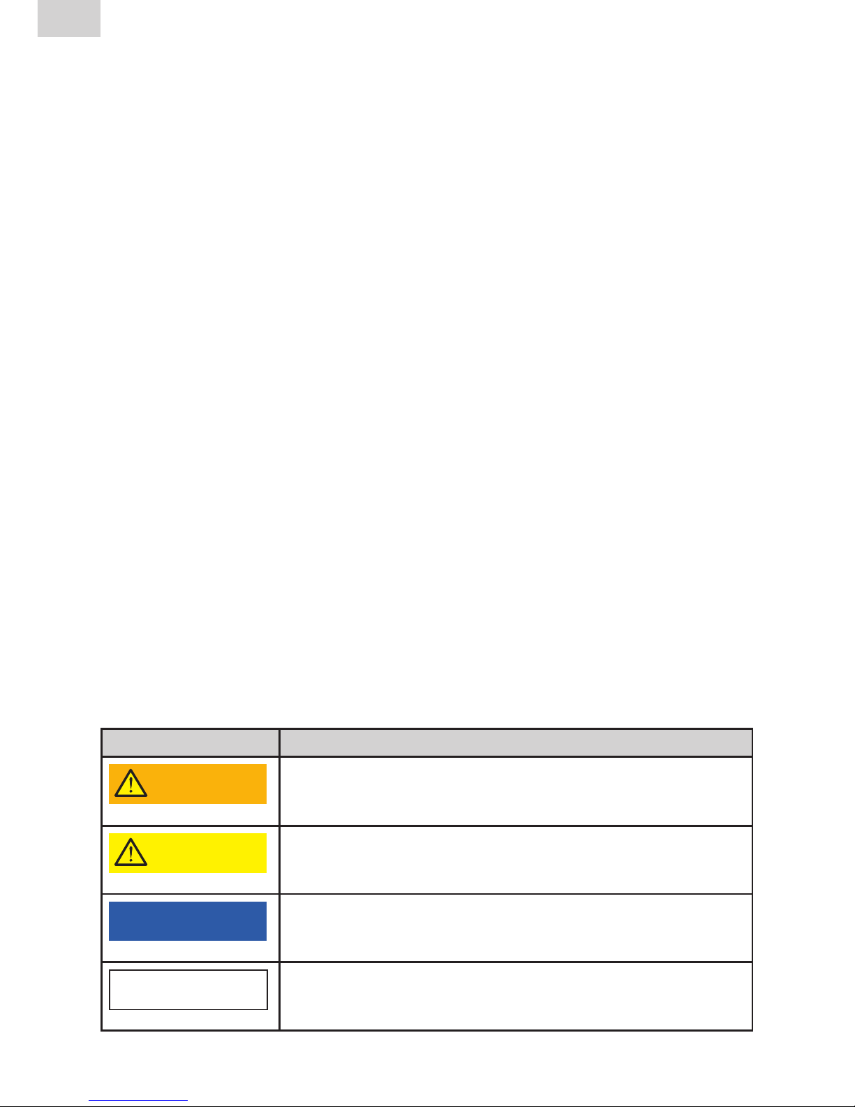
Diese Bedienungsanleitung verwendet folgende Symbole mit Warnhinweisen:
Symbol Bedeutung
WARNUNG!
Gefahr für Personen.
Nichtbeachtung kann zu Tod oder schweren
Verletzungen führen.
VORSICHT!
Gefahr für Personen.
Nichtbeachtung kann zu leichten oder mittleren
Verletzungen führen.
HINWEIS
Gefahr für Gegenstände.
Nichtbeachtung kann zu Sachschäden führen.
INFORMATION
Anwendungstipps und andere nützliche Informationen.
Nichtbeachtung kann nicht zu Personen- oder Sachschäden führen.
1. Vorbemerkungen 2
1.1 Sicherheitshinweise 2
1.2 Bestimmungsgemäße Verwendung 3
2. Sicherheit 3
2.1 Sicherheitshinweis 3
2.2 Verpflichtungen des Betreibers 4
2.3 Bauliche Veränderungen am Gerät 4
3. Lieferumfang 4
3.1 Einsatz einer Vakuumpumpe 6
4 Vorbereitung der Schweißung 6
5. Montage 7
5.1 Montage des Presskolbens (nur bei Stutzensattel) 7
5.2 Montage des Vakuum-Aufspanngeräts 8
6. Schweißung durchführen 11
7. Demontage 12
8.
Anbohrung und Inbetriebnahme (nur bei Stutzensattel) 12
9.
Pflege- und Servicehinweise 13
10. Gewährleistung 14
11. Aktualisierung dieser Bedienungsanleitung 14
Inhaltsverzeichnis
3
Update/Stand: 11.2017
DE
1.2 Bestimmungsgemäße Verwendung
Die FRIATOOLS-Aufspannvorrichtung VACUSET XL in Verbindung mit dem
Presskolben (nennweitenbezogen) dient zur Montage von FRIALEN XL Stutzensätteln SA-XL d 400 bis d 1200 mm mit Abgang d 160, d 225 , d 250, d 315,
d 355 und d 400 und FRIAFIT Stutzensätteln ASA-VL d 355 bis d 630 mit Abgang d 225.
Die FRIATOOLS-Aufspannvorrichtung VACUSET XL dient auch zur Montage
von FRIALEN XL Reparatursätteln RS-XL zur Reparatur von lokal begrenzten
Schäden an PE-Großrohren d 500 bis d 1200 mm.
Das VACUSET XL ist im Temperaturbereich von -10 bis +45°C und in Höhenlagen bis 1000 m einsetzbar. Bei abweichenden Einsatzbedingungen wenden
Sie sich bitte an unsere Anwendungstechnik.
Die FRIATOOLS-Aufspannvorrichtung VACUSET XL arbeitet mit Vakuum. Für
die Erzeugung des Unterdrucks ist ein Kompressor erforderlich. Bedienungsanleitung und Arbeitstemperaturbereich des Kompressors sind zu beachten.
Diese Bedienungsanleitung gilt ergänzend zu den Vorgaben der Montageanleitung FRIALEN XL-Großrohrtechnik und FRIAFIT-Abwassersystem sowie der
Bedienungsanleitung Anbohrset FWAB XL / FWAB ASA.
HINWEIS
Kesselkompressoren sind im Arbeitstemperaturbereich unter 5°C für die
Anwendung nicht zugelassen!
2. Sicherheit
2.1 Sicherheitshinweis
Zur Vermeidung von Personen- und Sachschäden müssen folgende grundsätzlichen Punkte beachtet werden:
• Prüfen Sie vor Inbetriebnahme den ordnungsgemäßen Zustand der Ausrüstung
• Achten Sie darauf, dass die Luftauslassöffnung der VACUBOX XL nicht
gegen den Anwender oder gegen Staub und Schmutz bläst. Die Luftauslassöffnung muss frei liegen.
• Tragen von Schutzausrüstung, insbesondere einer Schutzbrille.
• Der Presskolben des VACUSET XL ist ausschließlich für Vakuumanwendungen vorgesehen.

4
Update/Stand: 11.2017
DE
2.2 Verpflichtungen des Betreibers
Alle Personen, die mit der Inbetriebnahme, Bedienung, Wartung, Instandhaltung und bestimmungsgemäßen Verwendung der Aufspannvorrichtung
VACUSET XL sowie den zusätzlich erforderlichen Geräten (z.B. Stromerzeuger,
Kompressor) betraut sind, müssen:
• entsprechend qualifiziert sein und
• diese Bedienungsanleitung genau beachten.
Die Bedienungsanleitung ist stets am Einsatzort der Aufspannvorrichtung
VACUSET XL, am Besten im Transportkoffer, aufzubewahren. Sie muss
jederzeit für den Bediener einsehbar sein.
Beachten Sie bei der bestimmungsgemäßen Verwendung die gültigen Unfallverhütungsvorschriften, Umweltvorschriften und gesetzlichen Regeln, ebenso
die einschlägigen Sicherheitsbestimmungen sowie alle länderspezifischen
Normen, Gesetze und Richtlinien.
2.3 Bauliche Veränderungen am Gerät
Ohne die Genehmigung der FRIATEC AG dürfen keine Veränderungen, Anoder Umbauten an der Aufspannvorrichtung VACUSET XL durchgeführt
werden.
3. Lieferumfang
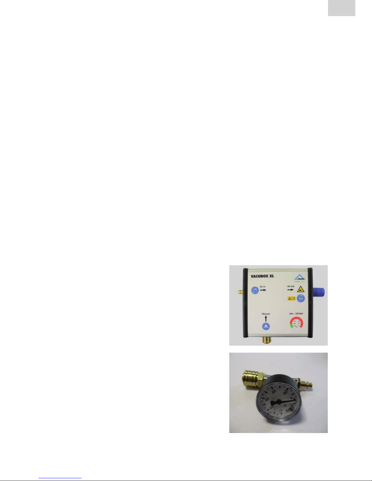
• VACUBOX XL mit integrierter Venturidüse und
Schalldämpfer (blau)
• Manometer (am T-Stück) mit Stecknippel und
Kupplung NW 7,2

5
Update/Stand: 11.2017
DE
• Spiralleitung (blau) ca. 5m mit Stecknippel
und Kupplung NW 7,2)
• Übergangsadapter von Stecknippel NW 7,2
auf Klauenkupplung (vormontiert an der
Kompressor-Anschlussleitung)
• Kompressor-Anschlussleitung (schwarz)
ca. 0,8m mit Stecknippel und Kupplung
NW 7,2
• Sattel-Anschlussleitung (blau) ca. 2,5m mit
Stecknippel und Kupplung NW 7,2
• Bedienungsanleitung
• Alu-Transportkiste
Für die Montage der Stutzensättel werden zusätzlich nennweitenbezogene
Presskolben mit Anschlagplatte und Stecknippel NW 7,2 benötigt. Diese sind
im Lieferumfang VACUSET XL nicht enthalten und müssen separat bestellt
werden.

6
Update/Stand: 11.2017
DE
Art.-Bez. Abgangsdimension
Stutzensattel
Best.-Nr.
Presskolben d 160 d 160 613821
Presskolben d 225 d 225 613822
Presskolben d 250 SA-XL: d 250
ASA-VL: d 225
613823
Presskolben d 280 d 280 613853
Presskolben d 315 d 315 613854
Presskolben d 355 d 355 613855
Presskolben d 400 d 400 613837
3.1 Einsatz einer Vakuumpumpe
Alternativ zur VACUBOX XL in Verbindung mit einem Kompressor kann eine
Vakuumpumpe eingesetzt werden. Anschluß, Montage und Demontage erfolgen sinngemäß zu der hier beschriebenen Bedienung.
WARNUNG!
Die Vakuumpumpe darf nur außerhalb des Baustellengrabens eingesetzt werden. Soll die Vakuumpumpe auch im Graben zur Anwendung kommen, muss
nach BGI 594 und BGI 534 zwingend eine geeignete Fehlerstromschutzeinrichtung (FI-Schalter) in die Geräteanschlussleitung zwischengeschaltet werden.
Der hierzu erforderliche FI-Schalter (< 30 mA) muss für tiefe Temperaturen ausgelegt sein (Symbol „Schneeflocke“). Bei Anwendung innerhalb des Grabens
muss eine tägliche Prüfung des FI-Schalters durchgeführt werden.
HINWEIS
Die Inbetriebnahme der Vakuumpumpe darf nur unter den dafür zulässigen Bedingungen (z.B. trockener Arbeitsraum, Umgebungstemperaturbereich)
erfolgen.
4 Vorbereitung der Schweißung
• Säubern Sie die zu schälende Rohrfläche von Verunreinigungen wie Sand
und Erde (z.B. mit einem sauberen, fettfreien Lappen).
• Schweißzone auf dem PE-Rohr abmessen, markieren und Oxidhaut mit
geeignetem Schälgerät oder Handschaber entfernen.

7
Update/Stand: 11.2017
DE
HINWEIS
Das Schälen vor der Schweißung ist in jedem Falle durchzuführen!
Bei nicht vollständiger Entfernung der Oxidhaut kann es zu einer undichten Schweißverbindung kommen.
• Reinigen Sie die zu schweißende Sattelfläche sowie Sattelinnenseite mit
einem geeigneten PE-Reinigungsmittel und ausschließlich mit saugfähigem,
nicht fasernden und nicht eingefärbten Papier.
• Stutzensattel oder Reparatursattel auf dem PE-Rohr aufsetzen.
5. Montage
5.1 Montage des Presskolbens (nur bei Stutzensattel)
HINWEIS
Nach längerer Lagerung des Presskolbens kann das Fett an den Gummiringen
eventuell hart werden. Für die Montage des Presskolbens entfernen Sie daher
in diesem Fall alte Fettrückstände von den Gummiringen und fetten Sie diese
mit handelsüblicher Vaseline DAB10 leicht neu ein. Beachten Sie die Pflegeund Servicehinweise unter Punkt 9!
WARNUNG!
Presskolben ausschließlich für Vakuumanwendungen einsetzen!
Eine Beaufschlagung mit Überdruck ist aufgrund der Unfallgefahr ausdrücklich nicht
zulässig! Bitte beachten Sie die länderspezifischen Unfallverhütungsvorschriften!
Stellen Sie den Stutzensattel mit der Sattelfläche auf einen sauberen
Untergrund, z.B. auf einen Karton und montieren Sie die Gerätschaften wie im
Folgenden beschrieben:
Abb. 1
• Den Presskolben in den Abgang des Stutzensattels
einschieben, bis die Anschlagplatte an der Stutzenstirnkante anliegt.
• Flügelmutter handfest - ohne Einsatz von Werkzeug
- anziehen, so dass sich die Gummiringe an der
Abgangsinnenwand verpressen (Abb. 1).

8
Update/Stand: 11.2017
DE
5.2 Montage des Vakuum-Aufspanngeräts
• Montieren Sie das Manometer
Abb. 2
• bei Verarbeitung eines Stutzensattels entweder an der VACUBOX XL (Abb. 2) oder
alternativ am Presskolben (in Abhängigkeit
der Verarbeitungssituation) oder
• bei Verarbeitung eines Reparatursattels an
der VACUBOX XL.
HINWEIS
Beachten Sie beim Anschließen der Leitungen die Markierungen/Piktogramme
auf der VACUBOX XL!
Vacuum:
Zum Anschluss des FRIALEN XL Stutzensattels SA-XL oder
FRIALEN XL Reparatursattels RS-XL.
Air in:
Zum Anschluss des Baustellenkompressors.
Air out:
Luftauslass.
HINWEIS
Kompressor ausblasen lassen!
Vor dem Anschluss der VACUBOX XL und sämtlicher Leitungen den Kompressor zur
Reinigung kurz ausblasen lassen, damit keine Verunreinigungen in die Venturidüse
gelangen!
HINWEIS
Verschmutzung der Venturidüse vermeiden!
Ein Verschmutzen der Venturidüse kann zu einem Druckverlust führen! Eventuell ist
dann der Schalldämpfer der VACUBOX XL zu reinigen bzw. zu tauschen.

9
Update/Stand: 11.2017
DE
• Die Sattel-Anschlussleitung und die Spiralleitung miteinander verbinden.
• Die Sattel-Anschlussleitung und Spiralleitung mit der VACUBOX XL und
wie in Abb. 3 und Abb. 5 mit dem Anschluss am Sattel verbinden.
• Für die Verarbeitung des Stutzensattels wird das Leitungsstück mit
Kupplung NW 7,2 mit dem Presskolben verbunden (Abb. 4 und Abb. 5).
• Für die Verarbeitung des Reparatursattels wird das Leitungsstück mit
Kupplung NW 7,2 nicht verbunden. Die Kupplung ist im ungesteckten
Zustand geschlossen.
Abb. 3
Abb. 4
Abb. 5
HINWEIS
Originalschlauch verwenden!
Die VACUBOX XL sollte ausschließlich mit dem Originalschlauch an die Druckluftquelle angeschlossen werden. Werden andere Komponenten eingesetzt, kann dies
ggf. zu erhöhtem Druckverlust und damit Minimier ung der Vakuumleistung führen.
• VACUBOX XL und Druckluftkompressor über die Kompressor-Anschlussleitung miteinander verbinden.
• Prüfen Sie den korrekten und dichten Sitz aller Verbindungsstellen im
System.
• Die VACUBOX XL auf einer trockenen und sauberen Unterlage mit der
Beschriftung nach oben ablegen.
WARNUNG!
Austretende Luft kann zu Verletzungen führen!
Stellen Sie sicher, dass der Luftauslass an der VACUBOX XL immer frei liegt und
nicht gegen den Anwender oder gegen Staub oder Schmutz bläst.
Nicht in den Luftauslass schauen, wenn die VACUBOX XL in Betrieb ist. Schutzausrüstung tra gen!

10
Update/Stand: 11.2017
DE
Mindestanforderungen an den Druckluftkompressor:
Luftfilter erforderlich
Ausgangsleistung min. 150 l/min (9 m³/h)
Betriebsdruck min. 4-6 bar; max. 10 bar
Für Kompressoren mit Kessel:
Kesselvolumen min. 50 l
Kesseldruck min. 5 bar
HINWEIS
VACUBOX XL nur mit gefilterter Luft betreiben!
Ein Verschmutzen der Venturidüse in der VACUBOX XL kann zu einer Minimierung
der Vakuumleistung führen! Eventuell ist dann der Schalldämpfer der VACUBOX XL
zu reinigen oder zu tauschen.
• Den Druckluftkompressor einschalten.
HINWEIS
Die Vakuumspanntechnik kann nicht in Höhenlagen über 1000 m eingesetzt
werden. Wenden Sie sich in diesem Fall an unsere Anwendungstechnik.
• Den Sattel aufnehmen und gegen das Rohr drücken, bis das Vakuum den
Sattel auf das Rohr aufspannt und das Manometer ein konstantes Vakuum
von mindestens -0,8 bar anzeigt.
INFORMATION
Bei großer Ovalität des Rohres kann ggf. kein Vakuum erzeugt werden. Dann
den Sattel mittels zwei Spanngurten auf das Rohr drücken. Die Spanngurte
dabei an den Sattelflanken positionieren und gerade ausrichten. Wenn ein
konstantes Vakuum von mindestens -0,8 bar angezeigt wird Spanngurte lösen
und entfernen.

11
Update/Stand: 11.2017
DE
6. Schweißung durchführen
HINWEIS
Über die gesamte Verarbeitungszeit bis Ende der Abkühlzeit ist das Vakuum
am Manometer zu kontrollieren und es sind mindestens -0,8 bar aufrecht zu
erhalten!
HINWEIS
Vor Start der Schweißung muss der Sattel mindestens 2 Minuten unter Vakuum
von mindestens -0,8 bar auf dem Rohr aufgespannt werden.
• Vorwärmung starten.
• Direkt im Anschluß Schweißung starten. Beachten Sie die Bedienungsanleitung des FRIAMAT-Schweißgeräts.
HINWEIS
Bei Betrieb des Schweißgerätes darf kein weiterer Stromabnehmer an den
Stromgenerator angeschlossen sein. Ggf. wird ein zweiter Stromgenerator
benötigt.
VORSICHT!
Halten Sie aus allgemeinen Sicherheitsgründen während der Schweißung
einen Abstand von einem Meter zur Schweißstelle.
HINWEIS
Nach Ablauf der Schweißung ist eine Haltezeit von mindestens 30 Minuten
unter Vakuum einzuhalten.

12
Update/Stand: 11.2017
DE
7. Demontage
• Nach Ablauf der Schweißzeit kann das Schweißgerät ausgeschaltet und das
Schweißkabel entfernt werden.
• Nach Ablauf der Haltezeit von mindestens 30 Minuten kann der Kompressor
ausgeschaltet werden.
• Die Schlauchanschlüsse, den Presskolben (nur beim Stutzensattel) und das
Manometer lösen und entfernen.
HINWEIS
Nach Demontage des Presskolbens sind eventuelle Rückstände von Vaseline
DAB10 am Stutzensattel sorgfältig zu entfernen; z.B. mit einem geeigneten PEReinigungsmittel. Ein Verschleppen des Schmierstoffes in Schweißbereiche ist
zu verhindern.
• Verstauen Sie das Equipment zu seinem Schutz wieder in der Transportbox.
8.
Anbohrung und Inbetriebnahme (nur bei Stutzensattel)
Die Anbohrung des Stutzensattels erfolgt mit dem FRIATOOLS Anbohrset
FWAB XL / FWAB ASA.
• Die folgenden Wartezeiten sind einzuhalten:
Abkühlzeit in Minuten für FRIALEN XL
Sattelformteile SA-XL und RS-XL
Von Schweißende bis zur Anbohrung
(unter Vakuumaufspannung)
Bis zur Druckbeaufschlagung über
den Abgang (CT)
30 Minuten 60 Minuten
Abkühlzeit in Minuten für FRIAFIT Sattelformteil ASA-VL
Von Schweißende bis zur Anbohrung
(unter Vakuumaufspannung)
Bis zur Aufbringung des Prüfdrucks
(0,5 bar) über den Abgang (CT)
10 Minuten 10 Minuten

13
Update/Stand: 11.2017
DE
9.
Pflege- und Servicehinweise
Alle Bauteile sind regelmäßig von Schmutz und Belag zu reinigen. Verwenden
Sie hierzu handelsüblichen Reiniger – keinen aggressiven Reiniger verwenden.
Die Aufspannvorrichtung VACUSET XL und Zubehörteile sind trocken und sauber zu lagern. Nach dem Gebrauch stets in der trockenen Transportbox aufbewahren. Der Temperaturbereich beim Lagern liegt zwischen -20°C und +70°C.
Bei Bedarf (z.B. bei längerer Lagerung) ist eventuell der Gummiring des Presskolbens mit handelsüblicher Vaseline DAB10 neu zu fetten. Drehen Sie hierzu
den Griff von der Gewindespindel, um die Durchgangsscheibe, Gewindescheibe und den Gummiring leicht einzufetten. Zuvor sind alte Fettrückstände
mit handelsüblichem, nicht aggressivem Reiniger zu entfernen.
Der Schalldämpfer der VACUBOX XL ist selbstreinigend. Verschmutzt dieser
dennoch mit der Zeit, ist der Schalldämpfer unter fließendem Wasser auszuspülen oder ggf. auszutauschen.
Art.-Bez. Best.-Nr.
Schalldämpfer 613840
HINWEIS
Ihre Kosten!
Ein sorgsamer Umgang mit dem VACUSET XL verhindert unnötige Repa raturen und
Ausfallzeiten. Eine regelmäßige, jährliche Überprüfung auf Funktionssicherheit, durch
den Service der FRIATEC AG, wird empfohlen.

14
Update/Stand: 11.2017
DE
10. Gewährleistung
Die Gewährleistung beträgt 1 Jahr. Hiervon ausgenommen sind Teile, die
durch das Umfeld (Sand, Erde, korrosionsfördernde Stoffe und Ähnlichem)
vorzeitig verschleißen.
Gewährleistungs- und Haftungsansprüche bei Personen- und Sachschäden
sind ausgeschlossen, wenn sie auf eine oder mehrere folgender Ursachen
zurückzuführen sind:
• Nicht bestimmungsgemäße Verwendung der Aufspannvorrichtung
VACUSET XL und des Presskolbens,
• bauliche, von FRIATEC AG gem. Ziff. 2.3 nicht genehmigte Veränderungen,
• unsachgemäße Handhabung und unsachgemäßer Transport,
• unsachgemäß ausgeführte Wartungs- oder Reparaturarbeiten,
• Nichtbeachten von Hinweisen dieser Bedienungsanleitung und/oder
• Einsatz von verschlissenen Funktionsteilen bzw. einer beschädigten
Aufspannvorrichtung VACUSET XL.
11. Aktualisierung dieser Bedienungsanleitung
Diese technischen Aussagen werden im Hinblick auf ihre Aktualität regelmäßig
geprüft. Das Datum der letzten Revision ist auf jeder Seite angegeben. Auf
dem neuesten Stand finden Sie die Bedienungsanleitung im Internet unter
www.friatools.de, über die Navigationsleiste erreichen Sie den Downloadbereich. Hier stehen Ihnen unsere aktuellen Bedienungsanleitungen als PDFDokumente zur Verfügung. Gerne senden wir Ihnen diese auch zu.

15
Update/Stand: 11.2017
EN
1. Preliminary notes
1.1 Safety notes and hints
In these operating instructions, the following symbols with warnings are used:
Symbol Bedeutung
WARNING!
Danger to people.
Failure to comply can result in death or serious injury.
CAUTION!
Danger to people.
Failure to comply can result in minor or moderate injury.
NOTICE
Danger to objects.
Failure to comply can result in objects damage.
INFORMATION
Application hints and other useful information.
Failure to comply can not result in personal inury or objects
damage.
1. Preliminary notes 15
1.1 Safety notes and hints 15
1.2 Designated use 16
2. Safety 16
2.1 Safety notes 16
2.2 Obligations of the operator 17
2.3 Structural changes 17
3. Scope of delivery 17
3.1 Use of a vacuum pump 19
4 Preparation of fusion 19
5. Assembly 20
5.1 Assembly of the plunger (only for spigot saddle) 20
5.2 Assembly of the vacuum clamping unit 21
6. Carrying out of fusion 24
7. Disassembly 25
8.
Tapping and commissioning (only for spigot saddle) 25
9.
Notes on care and maintenance 26
10. Warranty 27
11. Update of these operating instructions 27
Contents

16
Update/Stand: 11.2017
EN
1.2 Designated use
The FRIATOOLS clamping unit VACUSET XL in connection with the plunger
(nominal width-related) serves the installation of FRIALEN XL spigot saddles
SA-XL d 400 to d 1200 mm with outlet d 160, d 225, d 250, d 315, d 355 and
d 400 and FRIAFIT spigot saddles ASA-VL d 355 to d 630 with outlet d 225.
The FRIATOOLS clamping unit VACUSET XL also serves the installation of
FRIALEN XL repair saddles RS-XL. FRIALEN XL repair saddles RS-XL are used
to repair localised damages in large PE pipes d 500 to d 1200 mm.
The VACUSET XL can be deployed in a temperature range between -10°C and
+45°C and up to a maximum altitude of 1000 m. Please contact our Application Engineering department regarding any deviating operating conditions.
The FRIATOOLS VACUSET XL clamping unit operates with a vacu um. A
compressor is required to create the vacuum. Observe the operating instructions and operating temperature range of the compressor.
These operating instructions apply in connection with the assembly instruction
FRIALEN XL large pipe technique and FRIAFIT sewage system as well as the
operating instruction drilling device FWAB XL / FWAB ASA.
NOTICE
Tank compressors are not admitted for use at operating temperatures
below 5°C!
2. Safety
2.1 Safety notes
The following principal aspects must be observed to prevent injuries to persons
and damages to property:
• Check the proper condition of the equipment before use.
• Make sure that the air outlet of the VACUBOX XL does not discharge air in
the direction of the operator or into dust and dirt. The air outlet must be free
of obstructions.
• The operator is to wear protective clothing, in particular safety goggles.
• The plunger of the VACUSET XL is exclusively designed for vacuum applications.
17
Update/Stand: 11.2017
EN
2.2 Obligations of the operator
All persons involved in commissioning, operation, maintenance, repair and
intended use of the clamping unit VACUSET XL as well as the required additional equipment (e.g. power generator, compressor), must:
• be correspondingly qualified, and
• strictly observe these operating instructions.
The operating instructions must always be kept at the place of use of the
clamping unit VACUSET XL (transport box recommended). The instructions
must be available to the operator any time.
With regard to the intended use, please observe the accident prevention
regulations, environmental regulations and statutory rules, as well as the
relevant safety regulations and all local standards, laws and regulations.
2.3 Structural changes
No modifications, attachments or alterations in the clamping unit VACUSET XL
may be performed without approval by FRIATEC AG.
3. Scope of delivery
• VACUBOX XL with integrated venturi nozzle
and silencer (blue)
• Manometer (at T-piece) with plug connector
and NW 7.2 coupling

18
Update/Stand: 11.2017
EN
• Spiral hose (blue) approx. length 5m, with plug
connector and coupling NW 7.2
• Conversion adapter from plug connector NW
7.2 to claw coupling (pre-mounted on the
compressor connection hose)
• Compressor connection hose (black), approx.
length 0.8m, with plug connector and coupling
NW 7.2
•
Saddle connection hose (blue), approx. length
2.5m, with plug connector and coupling NW 7.2
• Operating instructions
• Aluminium transport box
For the assembly of the spigot saddles, nominal width-related plungers with
stop plate and plug connection NW 7.2 are required in addition. These are not
included in the scope of delivery of the VACUSET XL and must be ordered separately.

19
Update/Stand: 11.2017
EN
Article
description
Outlet dimension
spigot saddle
ORder-Ref.
Plunger d 160 d 160 613821
Plunger d 225 d 225 613822
Plunger d 250 SA-XL: d 250
ASA-VL: d 225
613823
Plunger d 280 d 280 613853
Plunger d 315 d 315 613854
Plunger d 355 d 355 613855
Plunger d 400 d 400 613837
3.1 Use of a vacuum pump
Alternatively to the VACUBOX XL a vacuum pump can be used in connection
with a compressor. Connection, assembly and disassembly occur correspondingly to the described operation in this manual.
WARNUNG!
The vacuum pump may only be used outside the construction site trench. If the
vacuum pump is also to be used in the trench, a suitable residual current circuit
breaker (RCD) is to be interposed in the unit‘s connection line according to the
guidelines of the accident prevention and insurance association (BGI 594 and
BGI 534). The required RCD (< 30mA) must be designed for low temperatures
(symbol “snowflake”). If the unit is to be used in the trench, the RCD must be
checked daily.
NOTICE
The initiation of the vacuum pump may only take place on permissible
conditions (e.g. dry working area, ambient temperature range).
4 Preparation of fusion
• Remove any contaminations such as sand and soil from the pipe surface to
be scraped (e.g. using a clean, fat-free cloth).
• Measure fusion zone on the PE pipe, mark and remove oxide layer with a
suitable scraper unit or manual scraper.

20
Update/Stand: 11.2017
EN
NOTICE
Scraping must be performed before fusion in any case.
If the oxide layer is not removed completely, leaking fusion joints may result.
• Clean the saddle area as well as the interior of the saddle with a suitable PE
cleaning agent and exclusively with absorbent, lint-free and non-dyed paper.
• Position the spigot saddle or the repair saddle on the PE pipe.
5. Assembly
5.1 Assembly of the plunger (only for spigot saddle)
NOTICE
After a longer period of storage of the plunger, the grease at the rubber rings
might have hardened. For the installation of the plunger, please thus remove in
this case all existing grease residues from the rubber rings and lubricate these
slightly again using commercially available Vaseline DAB10. Please observe the
notes on care and maintenance in item 9!
WARNING!
The plunger is exclusively intended for use under vacuum!
Any pressurisation with excess pressure is expressly not permitted because of the
risk of accidents! Please observe the country-specific accident prevention regulations!
Place the spigot saddle with the saddle area on a clean surface (e.g. on a box)
and assemble the equipment as described below:
• Insert the plunger into the outlet of the spigot saddle SA-XL until the stop
plate rests against the saddle front.
Fig. 1
• Securely hand-tighten the winged nut - without using
any tool - such that the rubber rings are pressed into
the outlet’s interior wall (Fig. 1).

21
Update/Stand: 11.2017
EN
5.2 Assembly of the vacuum clamping unit
• Mount the manometer
Fig. 2
• when processing a spigot saddle either to
the VACUBOX XL (Fig. 2) or alternatively at
the plunger (depending on the processing
situation), or
• when processing a repair saddle to the
VACUBOX XL.
NOTICE
When connecting the hoses, please observe the markings/pictographs at the
VACUBOX XL!
Vacuum:
To connect the FRIALEN XL spigot saddle SA-XL or the FRIALEN XL
repair saddle RS-XL.
Air in:
To connect the construction site compressor.
Air out:
Air outlet.
NOTICE
Blow out the compressor!
Before connecting the VACUBOX XL and all the feed lines, blow out the compressor
briefly to clean it so that no dirt can make its way into the venturi nozzle!
NOTICE
Avoid contamination of venturi nozzle!
Dirt in the venturi nozzle can cause a loss of pressure! It may then be necessary to
clean or replace the silencer on the VACUBOX XL.

22
Update/Stand: 11.2017
EN
• Connect the saddle connection hose with the spiral hose.
• Connect the saddle connection hose and spiral hose to the VACUBOX XL
and to the connection point on the saddle as shown in Figs. 3 and 5.
• For the processing of the spigot saddles the hose section with coupling
NW 7.2 is then connected to the plunger (Fig. 4 and Fig. 5).
• For the processing of the repair saddles the hose section with coupling
NW 7.2 is not connected. The clutch is closed when not connected.
Fig. 3
Fig. 4
Fig. 5
NOTICE
Use only the original hose!
The VACUBOX XL should only be connected to the compressed air source using the
original hose. If other components are used, this may possibly lead to increased
pressure drop and thus minimizing the vacuum performance.
• Connect the VACUBOX XL and the air compressor using the compressor
connection hose.
• Check all connections of the system for correct and tight seating.
• Place the VACUBOX XL on a dry and clean surface with the inscription
facing upward.
WARNING!
Discharging air can cause injuries!
Make sure that the air outlet of the VACUBOX XL is always unobstructed and does
not expel air in the direction of the operator or into dust and dirt. Do not look into the
air outlet when the VACUBOX XL is in operation. Wear protective clothing!

23
Update/Stand: 11.2017
EN
Minimum requirements for the air compressor:
Air filter required
Output rating min. 150 l/min (9 m³/h)
Operating pressure min. 4-6 bar; max. 10 bar
For compressors with tank:
Tank volume min. 50 l
Tank pressure min. 5 bar
NOTICE
VACUBOX XL may only be operated with filtered air!
Dirt in the venturi nozzle can minimise the vacuum performance! It may then be
necessary to clean or replace the silencer on the VACUBOX XL.
• Start the air compressor.
NOTICE
The vacuum clamping unit cannot be used at altitudes above 1,000 m. Please
contact our application engineering department in this case.
• Pick up the saddle and press it against the pipe until the vacuum clamps the
saddle into place and the manometer shows a constant vacuum of at least
-0.8 bar.
INFORMATION
In case of major out-of-roundness of the pipe, it may be that no vacuum can
be generated. In this case, press the saddle onto the pipe applying two lashing
straps. Position the lashing straps at the sides of the saddle and straighten.
Loosen and remove the lashing straps when a constant vacuum of at least
-0.8 bar is shown.

24
Update/Stand: 11.2017
EN
6. Carrying out of fusion
NOTICE
The vacuum is to be checked at the manometer during the entire processing
time up to the end of the cooling time and maintained at
least -0.8 bar!
NOTICE
The saddle must be clamped onto the pipe under a vacuum of at least -0.8 bar
for at least 2 minutes before fusion can be started.
• Start the fusion.
• Please observe the operating instructions of the FRIAMAT electrofusion unit.
NOTICE
During the operation of the fusion unit, no other power consumer may be connected to the current generator. A second current generator may be required.
CAUTION!
Keep a distance of one meter to the fusion site during the fusion process for
general safety reasons.
NOTICE
After completion of the fusion, a waiting time under vacuum of 30 minutes must
absolutely be adhered to!

25
Update/Stand: 11.2017
EN
7. Disassembly
• After expiry of the fusion time, the electrofusion unit can be switched off and
the fusion cable can be removed.
• After expiry of the waiting time of at least 30 minutes, the compressor can
be switched off.
• Loosen and remove the hose connections, the plunger (only for spigot
saddle) and the manometer.
NOTICE
After the disassembly of the plunger, any Vaseline DAB10 residues at the
FRIALEN XL spigot saddle SA-XL are to be thoroughly removed; e.g. using a
suitable PE cleaning agent. Any entrainment of the lubricant into the fusion
areas is to be prevented.
• Protect the equipment and store it again in the transport box.
8.
Tapping and commissioning (only for spigot saddle)
Tapping of the spigot saddle is made using the FRIATOOLS drilling device
FWAB XL / FWAB ASA.
• The following waiting times are to be observed:
Cooling time in minutes for FRIALEN XL
saddle fittings SA-XL and RS-XL
From fusion end to tapping
(under vacuum clamping)
Up to pressurisation via the outlet
(CT)
30 minutes 60 minutes
Cooling time in minutes for FRIAFIT saddle fitting ASA-VL
From fusion end to tapping
(under vacuum clamping)
Up to application of the test pressure
(0,5 bar) via the outlet (CT)
10 minutes 10 minutes

26
Update/Stand: 11.2017
EN
9.
Notes on care and maintenance
All component parts are to be regularly cleaned of dirt and deposits. Please
use a commercially available cleaning agent - do not use any aggressive
cleaning agents. The clamping unit VACUSET XL and accessories are to be
stored in a dry and clean place. After use, the tool is always to be stored in the
dry transport box. The temperature range for storing is -20°C to +70°C.
If required (e.g. after a longer period of storage), the rubber ring of the plunger
is to be re-lubricated using commercially available Vaseline DAB10. Remove
the handle from the threaded spindle and slightly grease the through washer,
the threaded washer and the rubber ring. Before, all grease residues are to be
removed using a commercially available, non-aggressive cleaning agent.
The silencer on the VACUBOX XL is self-cleaning. If it should get dirty over
time, however, it should be cleaned under running water or replaced as
necessary.
Article Order-Ref.
Silencer 613840
NOTICE
Your costs!
Careful handling of the VACUSET XL prevents unnecessary repairs and down times.
A regular annual check for functional safety by the service of FRIATEC AG is
recommended.

27
Update/Stand: 11.2017
EN
10. Warranty
The warranty is granted for 1 year. Excluded from this are parts which prematurely wear because of the environment (sand, earth, corrosion-promoting
materials and similar).
Warranty and liability claims in the event of injuries to persons and damages to
property shall be excluded if they are the result of one or several of the following causes:
• use of the clamping unit VACUSET XL and the plunger not according to its
intended use,
• structural modifications not approved by FRIATEC AG accord. to item 2.3.,
• improper handling and improper transport,
• improperly performed maintenance and repair work,
• non-observance of notes in these operating instructions, and/or
• use of worn work functional parts or of a damaged clamping unit
VACUSET XL.
11. Update of these operating instructions
These technical statements are regularly checked for their up-to-dateness.
The date of the last revision is stated on each page. For an updated version of
the operating instructions, please visit our website www.friatools.com on the
Internet. You will find the “Download” page on the navigation bar. This page
contains our updated operating instructions as pdf documents. We would also
be pleased to mail them to you on request.

2475 · Stand/Update: 11.2017
FRIATEC Aktiengesellschaft
Division Technische Kunststoffe
Postfach 7102 61 – 68222 Mannheim – Germany
Tel +49 621 486 1533 – Fax +49 621 486 2030
info-friatools@friatec.de
www.friatools.de
FRIATEC Aktiengesellschaft
Technical Plastics Division
P.O.B. 7102 61 – 68222 Mannheim – Germany
Tel +49 621 486 1533 – Fax +49 621 486 2030
info-friatools@friatec.de
www.friatools.com
 Loading...