

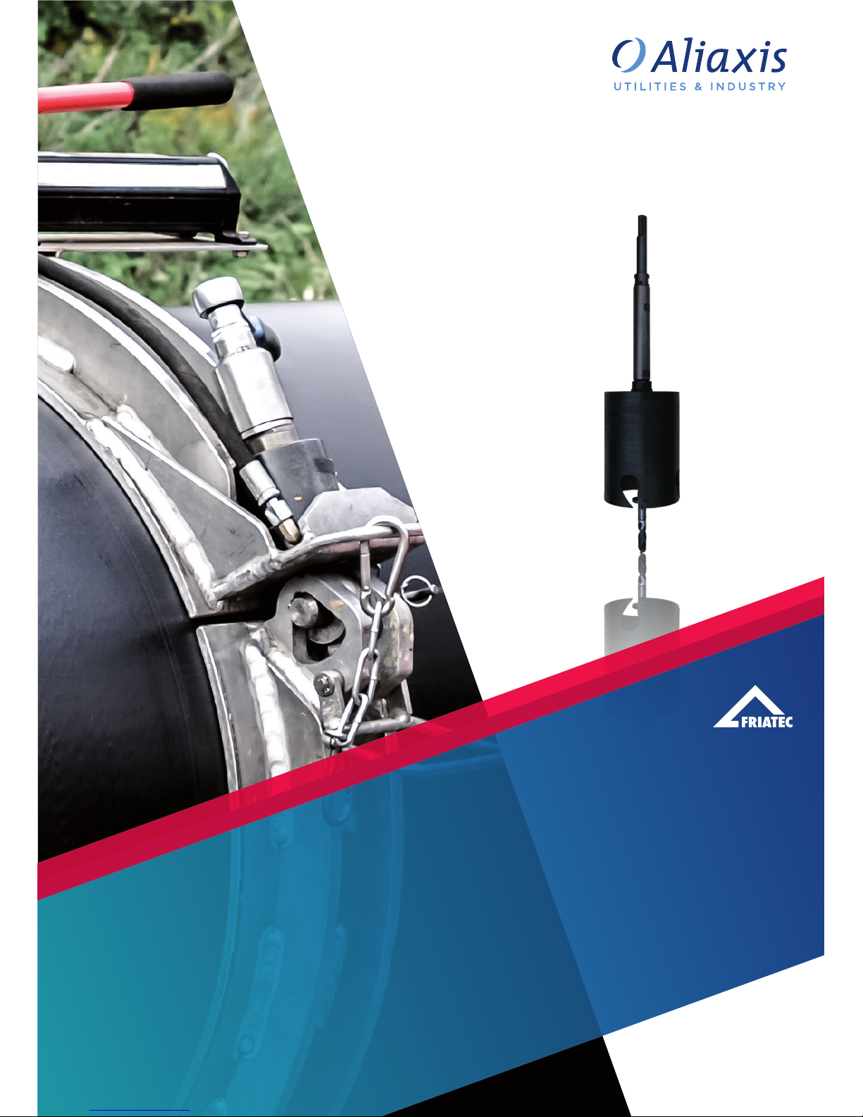
BEDIENUNGSANLEITUNG
ANBOHRSET FWAB
OPERATING INSTRUCTIONS
DRILLING DEVICE FWAB
www.friatools.de
2
Stand/Update: 11.2017
DE
1. Vorbemerkungen 2
1.1 Sicherheitshinweise 2
1.2 Bestimmungsgemäße Verwendung 3
2. Sicherheit 4
2.1 Sicherheitshinweise 4
2.2 Verpflichtungen des Betreibers 4
2.3 Bauliche Veränderungen 4
3. Lieferumfang 5
4. Zusammenbau/Montage 5
5. Bohrung durchführen 9
6. Pflege- und Servicehinweise 11
7. Gewährleistung 12
8. Aktualisierung dieser Bedienungsanleitung 12
Inhaltsverzeichnis Seite
1. Vorbemerkungen
1.1 Sicherheitshinweise
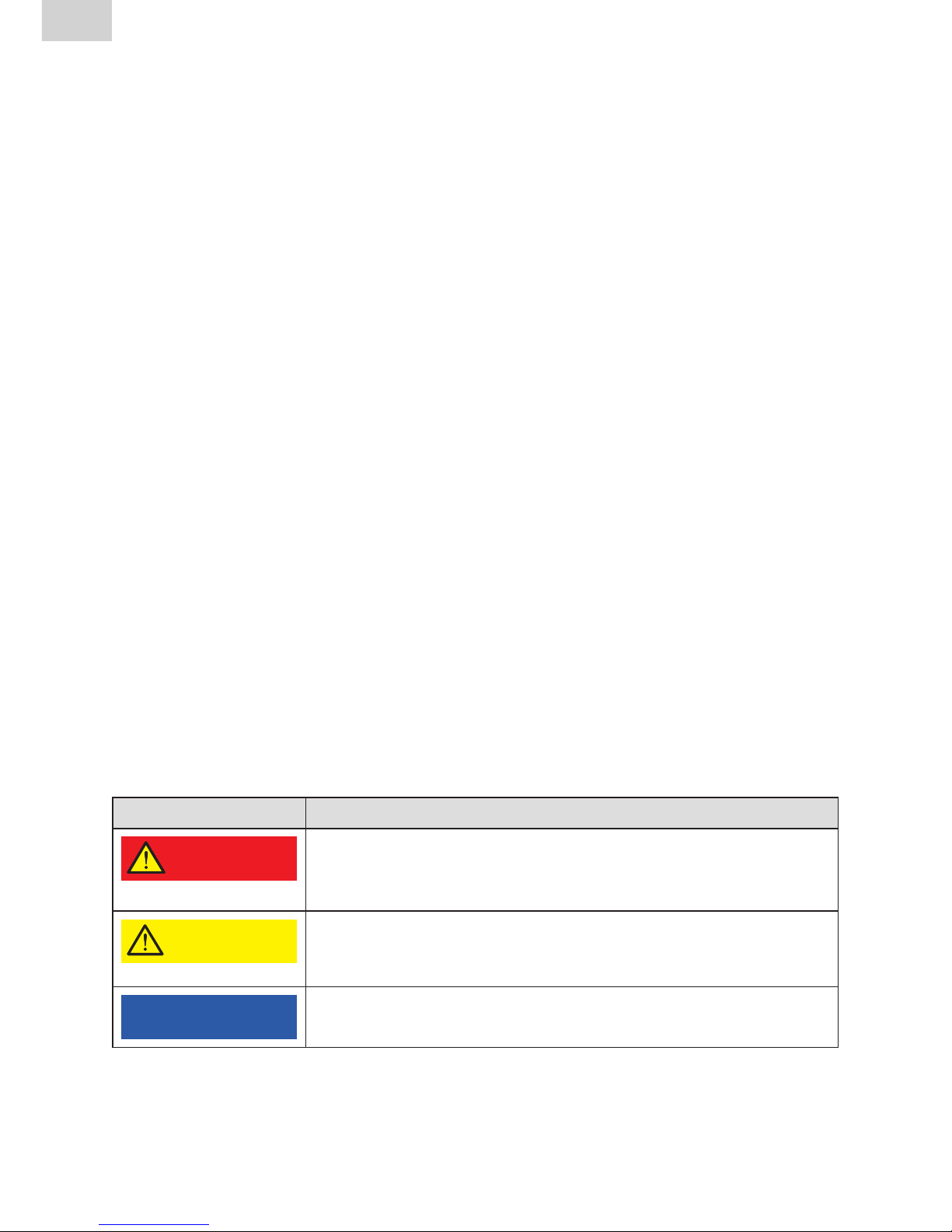
Diese Montageanleitung verwendet folgende Warnhinweise und Symbole:
Symbol Bedeutung
GEFAHR!
Gefahr für Personen.
Nichtbeachtung führt zu Tod oder schweren
Verletzungen.
VORSICHT
Gefahr für Personen.
Nichtbeachtung kann zu leichten oder mittleren
Verletzungen führen.
HINWEIS
Anwendungstipps und andere nützliche Informationen.
Nichtbeachtung kann nicht zu Personenschäden führen.
3
DE
Stand/Update: 11.2017
1.2 Bestimmungsgemäße Verwendung
Das FRIATOOLS-Anbohrset FWAB XL / FWAB ASA dient der Anbohrung von
PE-Hauptleitungen in drucklosem Zustand zur Herstellung eines Abzweigs.
Es wird über eine Bohrmaschine angetrieben und ist im Temperaturbereich von
-10°C bis +50°C anwendbar.
FWAB XL: Der Einsatzbereich umfasst PE-Rohre in den Dimensionen d 250 bis
d 1200, SDR 33 bis SDR 11 in Verbindung mit aufgeschweißten
FRIALEN Sattelbauteilen SA UNI und SA XL. Die Anbohrung erfolgt durch den
jeweiligen Abgangsstutzen der FRIALEN Sattelbauteile unter Verwendung der
Lochsäge gemäß Tabelle 1 und Tabelle 2.
FWAB ASA: Der Einsatzbereich umfasst PE-Rohre in den Dimensionen d 355 bis
d 900, SDR 17 bis SDR 11 in Verbindung mit aufgeschweißten FRIAFIT Abwasser-Sattelbauteilen ASA VL und Stutzenschellen ASA UNI. Die Anbohrung erfolgt
durch den jeweiligen Abgangsstutzen unter Verwendung der Lochsäge gemäß
Tabelle 3 und Tabelle 4.
Diese Bedienungsanleitung gilt in Verbindung mit der Montageanleitung
FRIALEN-XL Großrohrtechnik, der FRIAFIT Montageanleitung und der
Bedienungsanleitung VACUSET XL.
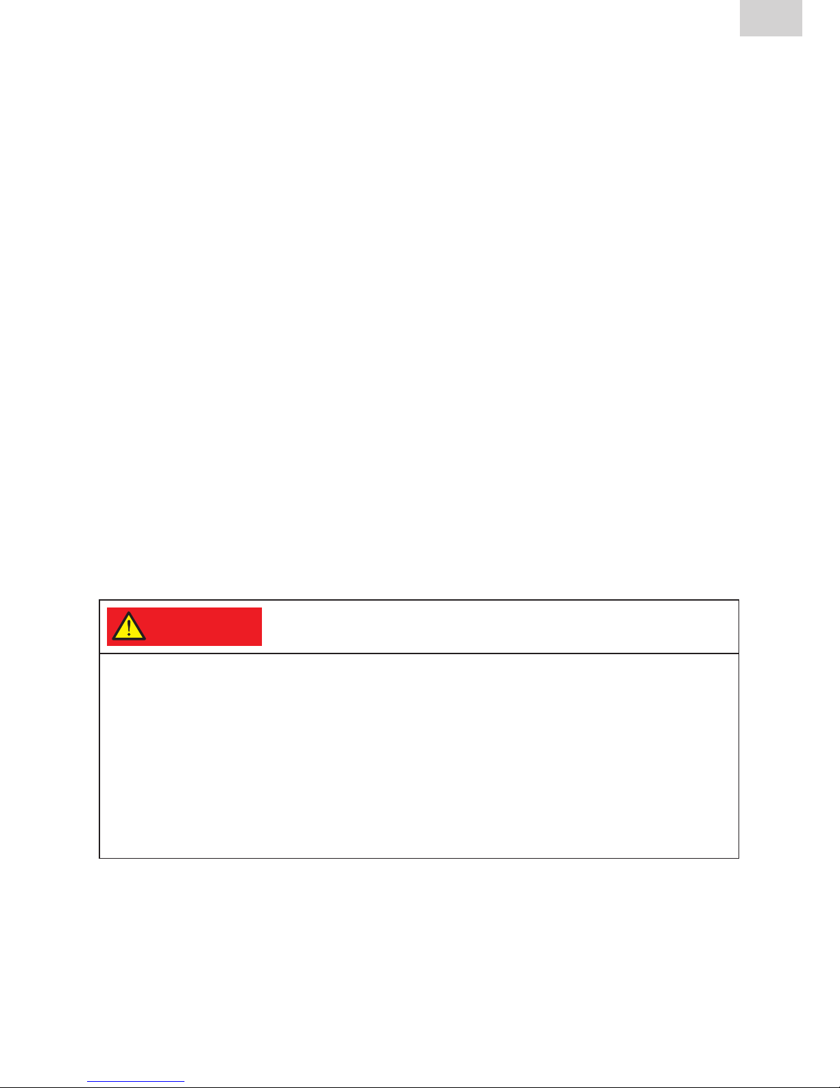
GEFAHR!
Nur drucklose und entleerte Leitungen anbohren!
Die Bohrung darf nur erfolgen, wenn die Leitung während der Arbeiten drucklos und
entleert ist. Insbesondere an Leitungstiefpunkten und / oder Anbohrung im Sohlenbereich besteht Gefahr durch elektrischen Strom bei Kontakt der Bohrmaschine
mit dem Medium. Es muss sichergestellt sein, dass sich in der Leitung kein explosives oder gesundheitsgefährdendes Gasgemisch befindet, bzw. bilden kann. Die
Unfallverhütungsvorschriften, insbesondere für das Arbeiten an Gasleitungen, z.B.
BGR 500 und die Richtlinien zum Einsatz von elektrischenBetriebsmitteln, z.B.
BGI 594 sowie das DVGW-Regelwerk oder landesspezifische Vorschriften sind zu
beachten und einzuhalten.
Zur bestimmungsgemäßen Verwendung gehört auch das Beachten aller
Hinweise dieser Bedienungsanleitung. Eine Abweichung vom bestimmungsgemäßen Gebrauch ist nicht zulässig!

4
Stand/Update: 11.2017
DE
2. Sicherheit
2.1 Sicherheitshinweise
Zur Vermeidung von Personen- und Sachschäden müssen folgende
grundsätzlichen Punkte beachtet werden:
• Beachten Sie die Bedienungsanleitung für die Bohrmaschine.
Nur Bohrmaschinen mit Sicherheitskupplung verwenden.
• Mindestanforderungen an die zu verwendende Bohrmaschine beachten
(siehe Kapitel 5).
• Prüfen Sie vor Inbetriebnahme den ordnungsgemäßen Zustand der
Aus rüstung.
• Stellen Sie vor jeder Tätigkeiten an der Lochsäge sicher, dass die
Bohr maschine von der Stromversorgung getrennt ist. Netzstecker ziehen!
• Auf sicheren Stand und ausreichende Bewegungsfreiheit im Arbeitsbereich
achten.
• Vorsicht beim Umgang mit der Lochsäge. Verletzungsgefahr an den
Hart metall schneiden, auch bei der Bohrkern- oder Spanentfernung.
• Bohrmaschine nur beidhändig bedienen.
• Tragen von Schutzausrüstung (z.B. Gehörschutz, Schutzbrille, etc.).
2.2 Verpflichtungen des Betreibers
Alle Personen, die mit der Inbetriebnahme, Bedienung, Wartung und
Instandhaltung sowie dem bestimmungsmäßigen Gebrauch des Anbohrsets
FWAB XL / FWAB ASA zu tun haben, müssen:
• Entsprechend qualifiziert sein und
• diese Bedienungsanleitung genau beachten.
Die Bedienungsanleitung ist stets am Einsatzort des Anbohrsets aufzube wahren
(am besten im Transportkoffer). Sie muss jederzeit für den Bediener einsehbar
sein.
Beachten Sie bei der bestimmungsgemäßen Verwendung die gültigen Unfallverhütungsvorschriften, Umweltvorschriften und gesetzlichen Regeln, ebenso die
einschlägigen Sicherheitsbestimmungen sowie alle länderspezifischen Normen,
Gesetze und Richtlinien.
2.3 Bauliche Veränderungen
Ohne die Genehmigung der FRIATEC AG dürfen keine Veränderungen,
An- oder Umbauten an dem Anbohrset FWAB XL / FWAB ASA durchgeführt
werden.
5
DE
Stand/Update: 11.2017
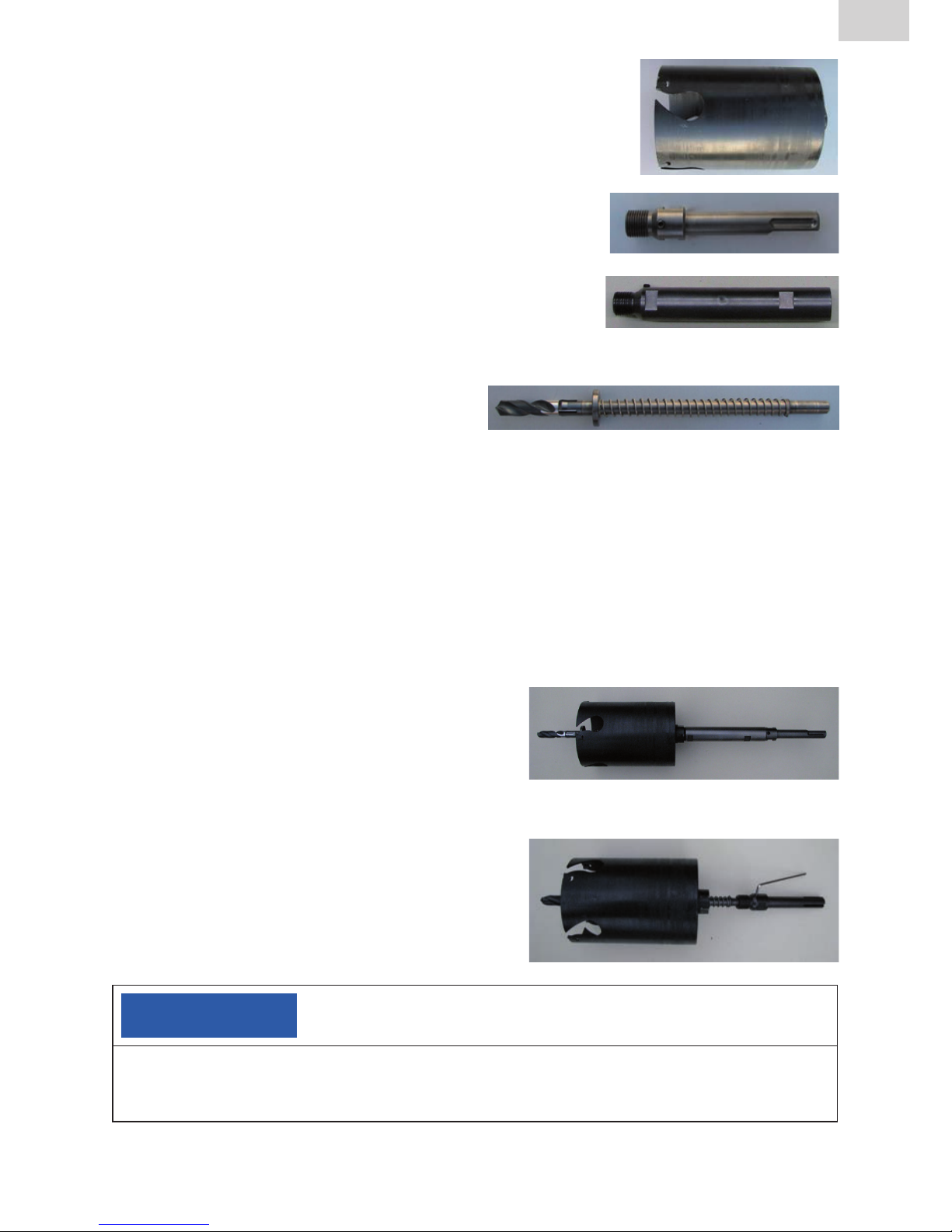
3. Lieferumfang
• Lochsäge für d90, d110, d125, d160,
d225, d250, d280, d315, d355 oder d400
• Lochsägenaufnahme SDS max
• Verlängerung für Lochsägenaufnahme
(nicht enthalten in FWAB d90, d110, d125 und
FWAB ASA d225)
• Zentrierbohrer mit Auswerfer
und Fanghülse
• Sechskantschlüssel
• Transportkoffer
• Bedienungsanleitung
4. Zusammenbau/Montage
• Montage mit Verlängerung, Zentrierbohrer und Aufnahme (Auslieferzustand).
Verwenden Sie die Verlängerung für die
Lochsägenaufnahme nur nach Tabelle 1.
• Montage ohne Verlängerung,
mit Zentrierbohrer und SDS-Aufnahme.
HINWEIS
Achten sie beim Zusammenbau von Lochsäge, Zentrierbohrer und Lochsägenaufnahme darauf, dass die Madenschraube der Lochsägenaufnahme auf die
dafür vorgesehene Abplattung am Schaft des Zentrierbohrers trifft!
6
Stand/Update: 11.2017
DE
Tabelle 1: Funktionswerte für die Anbohrung von Stutzensättel SA XL
FRIALEN
Stutzen-
sattel
SA XL
max.
zulässige
SDRStufe
Anbohrset
FWAB XL
Best.-Nr.
Ø
Loch-
säge
[mm]
Verlänge-
rung
[ja/nein]
d400/225 11 d225 613830 172 JA
d400/250 11 d250 613831 187 JA
d450/225 11 d225 613830 172 JA
d450/250 11 d250 613831 187 JA
d500/225 11 d225 613830 172 JA
d500/250 11 d250 613831 187 JA
d500/280 11 d280 613850 225 JA
d500/315 11 d315 613851 254 JA
d560/225 11 d225 613830 172 JA
d560/250 11 d250 613831 187 JA
d560/280 11 d280 613850 225 JA
d560/315 11 d315 613851 254 JA
d560/355 11 d355 613852 286 JA
d560/400 11 d400 613836 322 JA
d630/225 11 d225 613830 172 JA
d630/250 11 d250 613831 187 JA
d630/280 11 d280 613850 225 JA
d630/315 11 d315 613851 254 JA
d630/355 11 d355 613852 286 JA
d630/400 11 d400 613836 322 JA
d710/225 11 d225 613830 172 JA
d710/250 11 d250 613831 187 JA
d710/280 11 d280 613850 225 JA
d710/315 11 d315 613851 254 JA
d710/355 11 d355 613852 286 JA
d710/400 11 d400 613836 322 JA
d800/225 11 d225 613830 172 JA
d800/250 11 d250 613831 187 JA
d800/280 11 d280 613850 225 JA
d800/315 11 d315 613851 254 JA
d800/355 11 d355 613852 286 JA
d800/400 11 d400 613836 322 JA
7
DE
Stand/Update: 11.2017
Tabelle 1: Funktionswerte für die Anbohrung von Stutzensättel SA XL
FRIALEN
Stutzen-
sattel
SA XL
max.
zulässige
SDRStufe
Anbohrset
FWAB XL
Best.-Nr.
Ø
Loch-
säge
[mm]
Verlänge-
rung
[ja/nein]
d900/225 11 d225 613830 172 JA
d900/250 11 d250 613831 187 JA
d900/280 11 d280 613850 225 JA
d900/315 11 d315 613851 254 JA
d900/355 11 d355 613852 286 JA
d900/400 11 d400 613836 322 JA
d1000/160 17
d160 613829 123 JA
d1000/225 11
d225 613830 172 JA
d1000/250 11
d250 613831 187 JA
d1000/280
11 d280 613850 225 JA
d1000/315
11 d315 613851 254 JA
d1000/355
11 d355 613852 286 JA
d1000/400
11 d400 613836 322 JA
d1200/160
17 d160 613829 123 JA
d1200/225
11 d225 613830 172 JA
d1200/250
11 d250 613831 187 JA
d1200280
11 d280 613850 225 JA
d1200/315
11 d315 613851 254 JA
d1200/355
11 d355 613852 286 JA
d1200/400
11 d400 613836 322 JA
Tabelle 2: Funktionswerte für die Anbohrung von Stutzensätteln SA UNI
FRIALEN
Stutzensattel
SA UNI
max.
zulässige
SDR-Stufe
Anbohrset
FWAB XL
Best.-Nr.ØLochsäge
[mm]
Verlänge-
rung
[ja/nein]
max.
Eintauch-
tiefe [mm]
d250 – d280/90 SDR 11 d90 613832 66 NEIN 250
d250 – d280/110 SDR 11 d110 613833 82 NEIN 250
d250 – d280/125 SDR 11 d125 613834 94 NEIN 250
d250 – d280/160 SDR 11 d160 613829 123 NEIN 250
d315 – d400/90 SDR 11 d90 613832 66 NEIN 300
d315 – d400/110 SDR 11 d110 613833 82 NEIN 300
d315 – d400/125 SDR 11 d125 613834 94 NEIN 300
d315 – d400/160 SDR 11 d160 613829 123 NEIN 300
d450 – d800/90 SDR 11 d90 613832 66 NEIN 300
d450 – d800/110 SDR 11 d110 613833 82 NEIN 300
d450 – d800/125 SDR 11 d125 613834 94 NEIN 300
d450 – d800/160 SDR 11 d160 613829 123 NEIN 300
8
Stand/Update: 11.2017
DE
Tabelle 3: Funktionswerte für die Anbohrung von Abwassersätteln ASA VL
FRIAFIT
Abwassersattel
ASA VL
max. zulässige
SDR-Stufe
Anbohrset
FWAB ASA
Best.-
Nr.
Ø Lochsäge
[mm]
Verlängerung
[ja/nein]
max.
Eintauchtiefe
[mm]
d355 – d630/225 SDR 11* d225 613835 195 NEIN 450
* d560, d630: SDR 17
Tabelle 4: Funktionswerte für die Anbohrung von Stutzenschellen ASA UNI
FRIAFIT
Stutzenschelle ASA UNI
max. zulässige
SDR-Stufe
Anbohrset
FWAB ASA
Best.-Nr.
Ø Lochsäge
[mm]
Verlängerung
[ja/nein]
d630 – d900/160 17 d160 613838 137 JA
Bei Anbohrung von PE-Rohren SDR 11 setzen Sie sich bitte mit unserer
Anwendungs technik in Verbindung.
HINWEIS
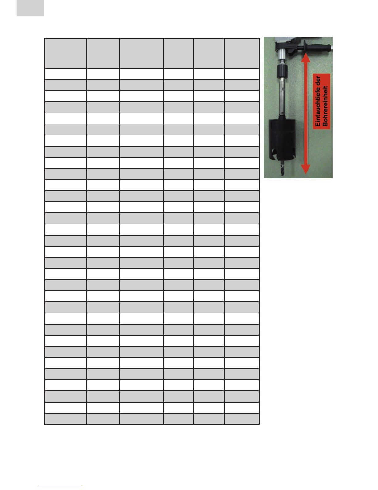
Eintauchtiefe beachten!
• Vermeiden Sie zu tiefes Eintauchen der Lochsäge, bzw. des Zentrierbohrers da die
innere Rohrwandung des Hauptrohres beschädigt werden kann. Machen Sie vor
allem bei Rohren ≤ d315 mit den Platzverhältnissen vertraut.
• Setzen Sie insbesondere die Verlängerung ausschließlich nach
Tabelle 1 ,2, 3 und 4 ein!
HINWEIS
Rohrwandung auf Beschädigungen prüfen!
Prüfen Sie nach erfolgter Anbohrung, ob Beschädigungen aufgetreten sind. Eine Beschädigung der Rohrwandung des Hauptrohres erfordert eine Reparatur, z.B. durch
Austausch.

9
DE
Stand/Update: 11.2017
5. Bohrung durchführen
Bohren erfolgt durch den Rohrstutzen des aufgeschweißten FRIALEN
Stutzensattel SA XL, SA UNI oder FRIAFIT Abwassersattel ASA VL und Stutzenschelle ASA UNI.
HINWEIS
Abkühlzeiten des Sattels beachten!
Empfohlene Mindestanforderungen an die Bohrmaschine:
Leistungsaufnahme 1700 W
Drehzahlbereich 300-700 U/Min
Lochsägenaufnahme SDS max
VORSICHT!
Nur Bohrmaschinen mit Sicherheitskupplung verwenden!
HINWEIS
Vorgehensweise bei FRIALEN Stutzensattel SA UNI
Die Anbohrung erfolgt in zwei Schritten:
1. Nach der Sattel-Schweißung wird im ersten Schritt der innere Teller des Stutzensattels SA UNI inklusive des Druckprüfungsstutzens ausgebohrt. Hierfür wird die
Lochsäge ohne Zentrierbohrer eingesetzt. Der Bohrvorgang wird unterbrochen und
der Teller entfernt. Sicherheitsvorgaben beachten!
2. Im zweiten Schritt wird der Zentrierbohrer montiert und nach erneutem Ansetzen
der Lochsäge die Rohrwand der Hauptleitung durchbohrt.

10
Stand/Update: 11.2017
DE
• Die Lochsäge mittig und senkrecht durch den Rohrstutzen des aufgeschweißten FRIALEN-Stutzensattels
SA XL, SA UNI oder FRIAFIT Abwassersattels ASA VL
und Stutzenschelle ASA UNI einsetzen. Wenn der
Zentrierbohrer an der Rohrober fläche ansteht, Maschine
beidhändig festhalten und einschalten.
• Lochsäge zentrisch im Stutzen führen und darauf achten,
dass die Innenfläche des Rohrstutzens nicht beschädigt
wird.
VORSICHT!
Blockieren der Lochsäge vermeiden!
Wird die Lochsäge während der Anbohrung verkantet oder
werden die Späne, wie unten beschrieben, nicht entfernt, kann
die Lochsäge schlagartig blockieren. Sorgen Sie für einen
sicheren Stand, vor allem bei Anbohrung des Rohrscheitels
und halten Sie die Bohrmaschine fest in beiden Händen.
• Mit langsamen Vorschub Zentrierloch bohren.
• Den Zentrierbohrer nach dem Durchbohren der Rohrwandung zur Spanentfernung mehrmals auf und ab bewegen, danach Bohrung mit geringem
Vorschub durchführen.
• Beim Bohren von dickwandigen PE-Rohren ist zu beachten, dass während
des Bohrvorgangs die Lochsäge zur Spanabführung in kurzen Abständen
bei rotierendem Werkzeug aus dem Bohrloch geführt wird.
VORSICHT!
Eventuell müssen Späne aus dem Inneren entfernt werden!
1. Bohrmaschine ausschalten und Lochsäge aus dem Rohrstutzen zie hen.
2. Bohrmaschine von Spannungsversorgung trennen; der Netzstecker ist zu ziehen.
3. Späne entfernen.
4. Anbohrvorgang fortsetzen.
• Nach der Fertigstellung der Bohrung Antrieb ausschalten und bei Stillstand
die Lochsäge vorsichtig aus dem Sattelabgang ziehen.

11
DE
Stand/Update: 11.2017
VORSICHT!
Verletzungsgefahr an den Hartmetallschneiden der Lochsäge!
Beim Entfernen von Bohrkern oder Spänen muss die Bohrmaschine von der
Span nungsversorgung getrennt sein. Der Netzstecker ist zu ziehen.
• Bohrkern und ggf. Späne entfernen
• Eventuell Späne im PE-HD-Rohr
entfernen
6. Pflege- und Servicehinweise
Alle Bauteile sind regelmäßig von Schmutz und Belag zu reinigen. Die Loch säge
und Zubehörteile sind trocken und sauber zu lagern. Nach dem Gebrauch stets
in der trockenen Transportbox aufbewahren. Der Tempe ratur bereich beim
Lagern liegt zwischen -20 °C und +70 °C.
HINWEIS
Reparaturen dürfen nur von autorisiertem FRIATEC-Servicepersonal durchgeführt werden!

12
Stand/Update: 11.2017
DE
7. Gewährleistung
Die Gewährleistung beträgt 1 Jahr. Hiervon ausgenommen sind Teile, die durch
das Umfeld (Sand, Erde, korrosionsfördernde Stoffe und Ähnlichem) vorzeitig
verschleißen. Gewährleistungs- und Haftungsansprüche bei Personen- und
Sachschäden sind ausgeschlossen, wenn sie auf eine oder mehrere folgender
Ursachen zurückzuführen sind:
• Nicht bestimmungsgemäße Verwendung des Anbohrsets,
• bauliche, von FRIATEC AG gem. Ziff. 2.3 nicht genehmigte Veränderungen,
• unsachgemäße Handhabung und unsachgemäßer Transport,
• unsachgemäß ausgeführte Wartungs- oder Reparaturarbeiten,
• Nichtbeachten von Hinweisen dieser Bedienungsanleitung und/oder
• Einsatz von verschlissenen Funktionsteilen bzw. eines beschädigten
Anbohrsets FWAB XL / FWAB ASA.
8. Aktualisierung dieser Bedienungsanleitung
Diese technischen Aussagen werden im Hinblick auf ihre Aktualität regelmäßig
geprüft. Das Datum der letzten Revision ist auf jeder Seite angegeben.
Auf dem neuesten Stand finden Sie die Bedienungsanleitung im Internet unter
www.friatools.de, über die Navigationsleiste erreichen Sie den Downloadbereich. Hier stehen Ihnen unsere aktuellen Bedienungsanleitungen als
PDF-Dokumente zur Verfügung. Gerne senden wir Ihnen diese auch zu.

13
EN
Stand/Update: 11.2017
Contents Page
1. Preliminary notes 13
1.1 Safety notes and hints 13
1.2 Intended use 14
2. Safety 15
2.1 Safety notes 15
2.2 Obligations of the operator 15
2.3 Structural changes 15
3. Scope of delivery 16
4. Assembly / installation 16
5. Drilling 20
6. Notes on care and maintenance 22
7. Warranty 23
8. Update of these operating instructions 23
1. Preliminary notes
1.1 Safety notes and hints
In these operating instructions, the following symbols with warnings are used:
Symbol Meaning
DANGER!
Danger to people.
Failure to comply will result in death or serious injury.
CAUTION!
Danger to people.
Failure to comply can result in minor or moderate injury.
NOTICE
Danger to objects.
Failure to comply can result in objects damage.

14
Stand/Update: 11.2017
EN
1.2 Intended use
The FRIATOOLS drilling device FWAB XL serves drilling of main PE pipings in
unpressurized condition to create a branch. It is driven by a drilling machine and
can be used in the temperature range of -10°C to +50°C.
FWAB XL: The area of application comprises PE pipes in the dimensions from
d 250 to d 1200, SDR 33 to SDR 11, in connection with fused-on FRIALEN
spigot-saddle SA UNI and SA XL. Drilling is made via the outlet spigots using
the hole saw ideally matched to the relevant situation according to table 1 and
table 2.
FWAB ASA: The area of application comprises PE pipes in the dimensions from
d 355 to d 900, SDR 17 to SDR 11, in connection with fused-on FRIAFIT spigotsaddle ASA VL and ASA UNI. Drilling is made via the outlet spigots using the hole
saw ideally matched to the relevant situation according to table 3 and table 4.
These operating instructions apply in connection with the assembly instructions
FRIALEN-XL Large Pipe Technique, the FRIAFIT assembly instructions and the
operating instructions VACUSET XL.
DANGER!
Drill only unpressurized and empty piping!
Drilling is only permitted with unpressurized and empty piping during working. Risk
of electrical current through contacts of the drilling machine with the medium in
particular exists at piping bottoms and/or drilling in the invert area. It must be
ensured that no explosive or harmful gas mixture exists or may be generated in
the piping. The accident prevention regulations, specifically for working at gas
pipings, e.g. BGR 500 and the use of electrical equipment, e.g. BGI 594, the DVGW
regulations or country-specific regulations are to be observed and fulfilled.
For a proper use, the hints in these operating instructions are to be observed.
Deviation from the intended use is not permitted!

15
EN
Stand/Update: 11.2017
2. Safety
2.1 Safety notes
The following principal aspects must be observed to prevent injuries to persons
and damages to property:
• Please observe the operating instructions for the drilling machine. Only use
drilling machines with safety couplers.
• Please observe the minimum requirements for the drilling machine to be
used (see Chapter 5).
• Check the proper condition of the equipment before use.
• Before any work on the hole saw, the drilling machine must be disconnected
from the power supply (disconnect mains plug!).
• Please ensure safe foothold and sufficient elbow-room in the working area.
• Caution when handling the hole saw. Risk of injury at the carbide blades,
• also when removing the drilling core or swarf.
• Use always both hands to operate the drilling machine.
• Wear protective equipment (e.g. ear protection, safety goggles, etc.).
2.2 Obligations of the operator
All persons involved in commissioning, operation, maintenance and repair as
well as the intended use of the drilling device FWAB XL / FWAB ASA must:
• be correspondingly qualified, and
• strictly observe these operating instructions.
The operating instructions must always be kept at the place of use of the drilling
device (transport box recommended). The instructions must be available to the
operator any time.
With regard to the intended use, please observe the valid accident prevention
regulations, environmental regulations and statutory rules, as well as the relevant
safety regulations and all local standards, laws and regulations.
2.3 Structural changes
No modifications, attachments or alterations in the drilling device FWAB XL /
FWAB ASA may be performed without approval by FRIATEC AG.

16
Stand/Update: 11.2017
EN
3. Scope of delivery
• Hole saw for d90, d110, d125, d160, d225,
d250, d280, d315, d355 or d400
• Hole saw adapter SDS max
• Extension for hole saw adapter
(not included in FWAB d90, d110, d125 and
FWAB ASA d225)
• Centre drill with ejector
and retaining shell
• Hexagon wrench
• Transport box
• Operating instructions
4. Assembly / installation
• Assembly with extension, centre drill
and SDS adapter (delivery condition).
Please only use the extension for the
hole saw adapter according to Table 1.
• Assembly without extension, with
centre drill and SDS adapter.
NOTICE
When assembling the hole saw, centre drill and hole saw adapter, please make
sure that the set screw of the hole saw adapter contacts the flattening at the
shaft of the centre drill designed for this purpose!

17
EN
Stand/Update: 11.2017
Table 1: Function values for drilling of spigot-saddles SA XL
FRIALEN
spigot saddle
SA XL
max.
permissible
SDR stage
Drilling
device
FWAB XL
Order-
Ref.
Ø
Hole
saw
[mm]
Extension
[yes/no]
d400/225 11 d225 613830 172 YES
d400/250 11 d250 613831 187 YES
d450/225 11 d225 613830 172 YES
d450/250 11 d250 613831 187 YES
d500/225 11 d225 613830 172 YES
d500/250 11 d250 613831 187 YES
d500/280 11 d280 613850 225 YES
d500/315 11 d315 613851 254 YES
d560/225 11 d225 613830 172 YES
d560/250 11 d250 613831 187 YES
d560/280 11 d280 613850 225 YES
d560/315 11 d315 613851 254 YES
d560/355 11 d355 613852 286 YES
d560/400 11 d400 613836 322 YES
d630/225 11 d225 613830 172 YES
d630/250 11 d250 613831 187 YES
d630/280 11 d280 613850 225 YES
d630/315 11 d315 613851 254 YES
d630/355 11 d355 613852 286 YES
d630/400 11 d400 613836 322 YES
d710/225 11 d225 613830 172 YES
d710/250 11 d250 613831 187 YES
d710/280 11 d280 613850 225 YES
d710/315 11 d315 613851 254 YES
d710/355 11 d355 613852 286 YES
d710/400 11 d400 613836 322 YES
d800/225 11 d225 613830 172 YES
d800/250 11 d250 613831 187 YES
d800/280 11 d280 613850 225 YES
d800/315 11 d315 613851 254 YES
d800/355 11 d355 613852 286 YES
d800/400 11 d400 613836 322 YES

18
Stand/Update: 11.2017
EN
Table 1: Function values for drilling of spigot-saddles SA XL
FRIALEN
spigot saddle
SA XL
max.
zulässige
SDRStufe
Drilling
device
FWAB XL
Order-
Ref.
Ø
Hole
saw
[mm]
Extension
[yes/no]
d900/225 11 d225 613830 172 YES
d900/250 11 d250 613831 187 YES
d900/280 11 d280 613850 225 YES
d900/315 11 d315 613851 254 YES
d900/355 11 d355 613852 286 YES
d900/400 11 d400 613836 322 YES
d1000/160 17
d160 613829 123 YES
d1000/225 11
d225 613830 172 YES
d1000/250 11
d250 613831 187 YES
d1000/280
11 d280 613850 225 YES
d1000/315
11 d315 613851 254 YES
d1000/355
11 d355 613852 286 YES
d1000/400
11 d400 613836 322 YES
d1200/160
17 d160 613829 123 YES
d1200/225
11 d225 613830 172 YES
d1200/250
11 d250 613831 187 YES
d1200280
11 d280 613850 225 YES
d1200/315
11 d315 613851 254 YES
d1200/355
11 d355 613852 286 YES
d1200/400
11 d400 613836 322 YES
Table 2: Function values for drilling of spigot-saddles SA UNI
FRIALEN
spigot saddle
SA UNI
max.
permissible
SDR stage
Drilling
device
FWAB XL
Order-
Ref.
Ø
Hole saw
[mm]
Extension
[yes/no]
maximum
penetration
depth [mm]
d250 – d280/90 SDR 11 d90 613832 66 NO 250
d250 – d280/110 SDR 11 d110 613833 82 NO 250
d250 – d280/125 SDR 11 d125 613834 94 NO 250
d250 – d280/160 SDR 11 d160 613829 123 NO 250
d315 – d400/90 SDR 11 d90 613832 66 NO 300
d315 – d400/110 SDR 11 d110 613833 82 NO 300
d315 – d400/125 SDR 11 d125 613834 94 NO 300
d315 – d400/160 SDR 11 d160 613829 123 NO 300
d450 – d800/90 SDR 11 d90 613832 66 NO 300
d450 – d800/110 SDR 11 d110 613833 82 NO 300
d450 – d800/125 SDR 11 d125 613834 94 NO 300
d450 – d800/160 SDR 11 d160 613829 123 NO 300

19
EN
Stand/Update: 11.2017
Table 3: Function values for drilling of spigot-saddles ASA VL
FRIAFIT
sewage saddle
ASA VL
max.
permissible
SDR stage
Drilling
device
FWAB ASA
Order-
Ref.
Ø Hole saw
[mm]
Extension
[yes/no]
maximum
penetration
depth [mm]
d355 – d630/225 SDR 11* d225 613835 195 NO 450
* d560, d630: SDR 17
Table 4: Function values for drilling of spigot-saddles ASA UNI
FRIAFIT
spigot saddle
ASA UNI
max.
permissible
SDR stage
Drilling device
FWAB ASA
Order-
Ref.
Ø
Hole saw
[mm]
Extension
[yes/no]
d630 – d900/160 17 d160 613838 137 YES
For drilling PE pipes SDR 11 please contact our Application Engineering
Department.
NOTICE
Observe the penetration depths of the drilling device!
• Avoid deep penetration of the hole saw or the centre drill because the interior pipe
wall of the main pipe could be damaged. Get acquainted with the available space,
specifically in case of pipes ≤ d315.
• Please only use the extension for the hole saw adapter according to table 1, 2, 3 and 4!
NOTICE
Check pipe wall for damages!
Check after drilling whether any damages occurred. Any damage to the pipe wall of
the main pipe requires repair, e.g. by replacement.

20
Stand/Update: 11.2017
EN
5. Drilling
Drilling is made through the pipe spigot of the fused-on FRIALEN spigot-saddles
SA UNI and SA XL
or FRIAFIT sewage saddle ASA VL and ASA UNI.
NOTICE
Please observe the cooling-down times of the saddle!
Recommended minimum requirements for the drilling machine:
Power consumption 1,700 W
Speed range 300-700 rpm
Hole saw adapter SDS max
CAUTION!
Only use drilling machines with safety couplers.
NOTICE
The procedure for the FRIALEN spigot saddle SA UNI.
The drilling shall be carried out in two steps:
1. After the saddle is fused the inner plate of the spigot saddle SA UNI is drilled
t ogether with pressure test port. Use the hole saw without centre drill. Interrupt
drilling and remove the plate.
2. In the second step, assemble the centre drill and again start drilling through the
pipe wall of the main with the hole saw.

21
EN
Stand/Update: 11.2017
• Position the hole saw in the centre and vertically through
the pipe spigot of the fused-on FRIALEN spigot saddle
SA UNI, SA XL or FRIAFIT sewage saddle ASA VL, ASA
UNI. When the centre drill contacts the pipe surface,
hold the machine with both hands and switch on.
• Guide the hole saw centrically in the spigot and ensure
that the inner surface of the pipe spigot is not damaged.
CAUTION!
Avoid blocking of the hole saw!
If the hole saw jams during drilling or if swarves are not
removed as described below, the hole saw may suddenly
lock. Ensure a safe foothold, specifically when drilling the
pipe crown and hold on to the drilling machine with both
hands. Drilling machines must be equipped with a safety
friction clutch.
• Drill the centre hole with slow speed.
• Having drilled through the pipe wall, move the centre drill up and down
several times to remove swarf, then drill with slow speed.
• When drilling thick-walled PE pipes, the rotating hole saw must be removed
from the drill hole in short intervals to remove swarf during the drilling.

22
Stand/Update: 11.2017
EN
CAUTION!
Swarf may have to be removed from the interior!
1. For removing, switch off the drilling machine and remove the hole saw from the
pipe spigot.
2. Disconnect drilling machine from power supply, disconnect mains plug.
3. Remove swarfs.
4. Continue with drilling.
• Having completed the drilling, switch off the drive and carefully remove the
idling hole saw from the saddle outlet.
CAUTION!
Risk of injury at the carbide blades!
When removing the drilling core and swarf the drilling machine must be disconnected
from the power supply, disconnect mains plug.
• Remove drilling core and swarf,
if any.
• Remove any swarf from inside
the HD-PE pipe.
6. Notes on care and maintenance
All component parts are to be regularly cleaned of dirt and deposits. The hole
saw and accessories are to be stored in a dry and clean place. After use, the tool
is always to be stored in the dry transport box. The temperature range for storing
is -20 °C to +70 °C.
NOTICE
Repairs may only be performed by authorised FRIATEC service personnel.

23
EN
Stand/Update: 11.2017
7. Warranty
The warranty is granted for one year. Excluded from this are parts which prematurely wear because of the environment (sand, earth, corrosion-promoting
materials and similar). Warranty and liability claims in the event of injuries to
persons and damages to property shall be excluded if they are the result of one
or several of the following causes:
• improper use of the drilling device,
• structural modifications not approved by FRIATEC AG accord. to item 2.3.,
• improper handling and improper transport,
• improperly performed maintenance and repair work,
• non-observance of notes in these operating instructions and/or
• use of worn functional parts or of a damaged drilling device FWAB XL /
FWAB ASA.
8. Update of these operating instructions
These technical statements are regularly checked for their up-to-dateness. The
date of the last revision is stated on each page.
For an updated version of the operating instructions, please visit our website
www.friatools.de on the Internet. You will find the “Download” page on the
navigation bar. This page contains our updated operating instructions as
pdf documents. We would also be pleased to mail them to you on request.

2441 · Stand/Update: 08.2017
FRIATEC Aktiengesellschaft
Division Technische Kunststoffe
Postfach 7102 61 – 68222 Mannheim – Germany
Tel +49 621 486 1533 – Fax +49 621 486 2030
info-friatools@friatec.de
www.friatools.de
FRIATEC Aktiengesellschaft
Technical Plastics Division
P.O.B. 7102 61 – 68222 Mannheim – Germany
Tel +49 621 486 1533 – Fax +49 621 486 2030
info-friatools@friatec.de
www.friatools.com
 Loading...