

Technical Equipment FRIALEN®/FRIAFIT
Operating Instructions
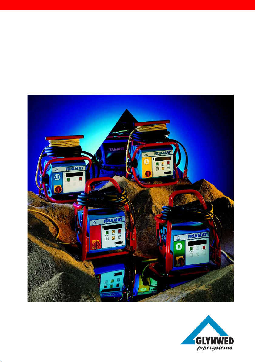
FRIAMAT® Fusion Units
®
37

Contents Page
1. SAFETY 4
1.1 Dangers 4
1.2 Safety hints and tips 4
1.3 Use in accordance with the requirements 5
1.4 Sources of Danger 6
1.5 Permitted users 6
1.6 Dangers from electrical power 6
1.7 Emissions 7
1.8 Safety precautions on site 8
1.9 Signal equipment 8
1.10 Emergencies 8
2. TECHNICAL DATA / TRANSPORT / COMMISSIONING 9
2.1 Technical data 9
2.2 Transport / storage / despatch 10
2.3 Setting up / connection 10
2.4 Putting into service 10
3. BASIC SETTINGS 11
3.1 Explanation of the function buttons 11
3.2 Date and time 12
3.3 Setting the signal volume 12
3.4 Setting the language 13
4. OPERATION 14
4.1 Construction / components 14
4.2 Functional principles 14
4.3 Fusion operating procedure 14
4.4 Preparation 14
4.5 Reading in the bar code 15
4.6 Starting the fusion process 16
4.7 Display voltage and frequency 17
2

5. AUXILIARY FUNCTION (ONLY FOR DOCUMENTATION UNITS) 18
5.1 Documentation 18
5.1.1 Switching on 18
5.1.2 Switching off 18
5.2 Operator’s Pass 19
5.3 Commission Numbers 20
5.3.1 Specifying and saving a commission number 20
5.3.2 Selecting saved commission numbers 21
5.3.3 Deleting saved commission numbers 21
5.3.4 Altering currently set (activated) commission numbers 22
5.3.5 Deactivating commission numbers 22
5.4 Info-text 22
5.5 Fusion Report 23
5.5.1 Print / delete the whole content of the memory 23
5.5.2 Printing out and deleting individual commission numbers 24
5.5.3 Deleting data without printing out the logs. 25
6. MAINTENANCE / TAKING OUT OF SERVICE 25
6.1 Warranty 25
6.2 Care and Maintenance instructions 25
6.3 Checking the reader wand 26
6.4 Taking out of service 26
7. OPERATING FAULTS 26
7.1 Faults when reading in the bar code 26
7.2 Emergency Input 26
7.3 Overheating 27
7.4 Fusion interruption 27
7.5 Fault messages / Warning messages 28
8. APPENDIX 30
8.1 Recommended accessories (options) 30
8.2 Authorised Service Centres world-wide 31
3
1. Safety
1.1 Dangers
The fusion units of the FRIAMAT® Family are constructed using state of the
art technology and in accordance with recognised safety rules, and are fitted
with the appropriate protective equipment. In addition to this the fusion units
of the FRIAMAT® Family are entitled to carry the TÜV GS Test Symbol as a
result of tests in line with the German Equipment Safety Law.
The fusion units of the FRIAMAT® Family have been checked for function and
for safety before being delivered. Incorrect operation or misuse, however,
can mean potential danger to
- the health of the operator,
- your FRIAMAT® model or other property of the user,
- the efficient operation of your FRIAMAT® model
All personnel who are in any way involved with the commissioning, operation,
maintenance or repair of the FRIAMAT® must
- be suitably qualified and
- comply precisely with these operating instructions.
This affects YOUR safety !
1.2 Safety hints and tips
This operating instruction employs the following SYMBOLS with WARNING
NOTES:
DANGER ! Describes an impending threat of danger !
Non-compliance with this instruction can result in severe damage to health
and property.
WARNING ! Describes a dangerous situation !
Non-compliance with this instruction can cause slight injuries or damage to
property
IMPORTANT ! Designates user tips and other useful information
4
1.3 Use in accordance with the requirements
The fusion units of the FRIAMAT® Family are exclusively for use in the fusion
of
- FRIALEN Safety Fittings with HD-PE pressure pipes (SDR 17-7)
and
- FRIAFIT Sewage Fittings with HD-PE sewage pipes (SDR 17 - 32)
Your FRIAMAT® model can also be used with fittings from other manufacturers
as long as they have been provided by the manufacturer with a bar code 2/5
interleaved to ANSI HM 10.8 M - 1983 or ISO CD 13950/08.94.
Using in according with the requirements also includes observing
- all the directions in this Operating Instruction and also
- the guidelines from the DVGW Code of Practice, from the DVS, the UVV
and the appropriate national and local regulations.
IMPORTANT ! Any other usage does not comply with the requirements !
FRIATEC AG accepts no liability for use which does not comply with the
requirements:
- Modifications or alterations are not permitted for safety reasons
- The fusion units of the FRIAMAT® Family must only be opened by an
electrical specialist
- Fusion with fusion units of the FRIAMAT® Family whose lead seals are
broken will render all claims for warranty and liability null and void.
Other examples of uses which contravene the requirements:
- use as a battery charger
- use as a power supply for heaters of any type
5
1.4 Sources of Danger
- Damaged connection leads and extension cables must be replaced
immediately
- Do not either remove safety devices or put them out of action
- Eliminate known faults immediately
- Do not leave your FRIAMAT® model unattended
- Keep away from flammable liquids / gases
- Do not operate in an Ex-environment
1.5 Permitted users
Only trained personnel may work with your FRIAMAT® model. The operator is
responsible for third parties in the working area The user must:
- make the operating instruction available to the operator and
- satisfy himself that the latter has read and understood them
1.6 Dangers from electrical power
- Do not use any damaged connecting cables
- Check the connection leads for damage
- Pull out the power supply plug before all care and maintenance work !
- Only have servicing, maintenance and repairs carried out by authorised
service centres
- Only connect the fusion units of the FRIAMAT® Family to the supply
voltage stated on the rating plate
WARNING ! Distribution points on the construction site: Comply with
the regulations on circuit breakers
Outdoors (on construction sites) sockets must be fitted with earth leakage
circuit breakers. If using generators the DVGW Work Sheet GW 308 and
VDE 0100 Part 728 must be complied with. The generator output rating
required is dependent on the power requirements for the largest fitting being
used, on connection conditions, ambient conditions and the actual generator
type (its control characteristics). Since generators from different model ranges
exhibit very different control characteristics the suitability of a generator
cannot always be guaranteed by the specified rated output alone.
6
In the event of doubt (e.g. when purchasing new) ask the authorised service
centre or request the “Positive Generator List” from FRIATEC AG.
Only use generators whose operating frequency lies within the range from
45 - 66 Hz.
First start the generator and let it run for half a minute. Set the off-load voltage
if necessary and limit it to the voltage specified in the technical data. !
Generator (mains) fuse max. 16 A (slow acting)
IMPORTANT ! Before starting the fusion process always check the input
voltage for your FRIAMAT® model from the Technical
Data (See Section 2.1 and 4.7)
If using an extension cable make sure the cross section is adequate:
- 2.5 mm2 up to 50 m and
-4 mm2 up to 100 m length.
Always unroll the cable fully before use. ! Do not connect any other equipment
to the same generator whilst fusion is taking place ! At the end of the fusion
operation first disconnect the power cable to the generator and then shut off
the generator.
DANGER ! Risk to life ! Never open your FRIAMAT® model whilst it is
connected to the power supply !
The fusion units of the FRIAMAT® Family are must only be opened by
specialist personnel from a recognised service centre !
1.7 Emissions
The (equivalent) continuous noise level from all fusion units of the FRIAMAT
Family is below 70 dB(A). When working in a quiet environment the effect of
the signal tone on the “Loud” setting is very loud. For this reason the signal
tone is adjustable (loud / quiet)
®
7

1.8 Safety precautions on site
IMPORTANT ! All the fusion units of the FRIAMAT® Family are splash
proofed. They must not be, however, dipped in water.
1.9 Signal equipment
The fusion units of the FRIAMAT® Family confirm certain operating processes
with an acoustic signal tone (1, 2, 5 tones or a continuous tone). These
signals have the following meanings:
Signal tone x 1 means: Confirmation of reading in a bar code
Signal tone x 2 means: Fusion process ended.
Signal tone x 3 means: Supply voltage too low / too high.
Signal tone x 5 means: Warning - Fault. Look at the display !
1.10 Emergencies
In an emergency switch the master switch to “OFF” immediately and
disconnect your FRIAMAT® model from the power supply ! The fusion units of
the FRIAMAT® Family can be stopped by:
- operating the master switch
- pulling out the power supply plug
8
2. Technical data / Transport / Commissioning
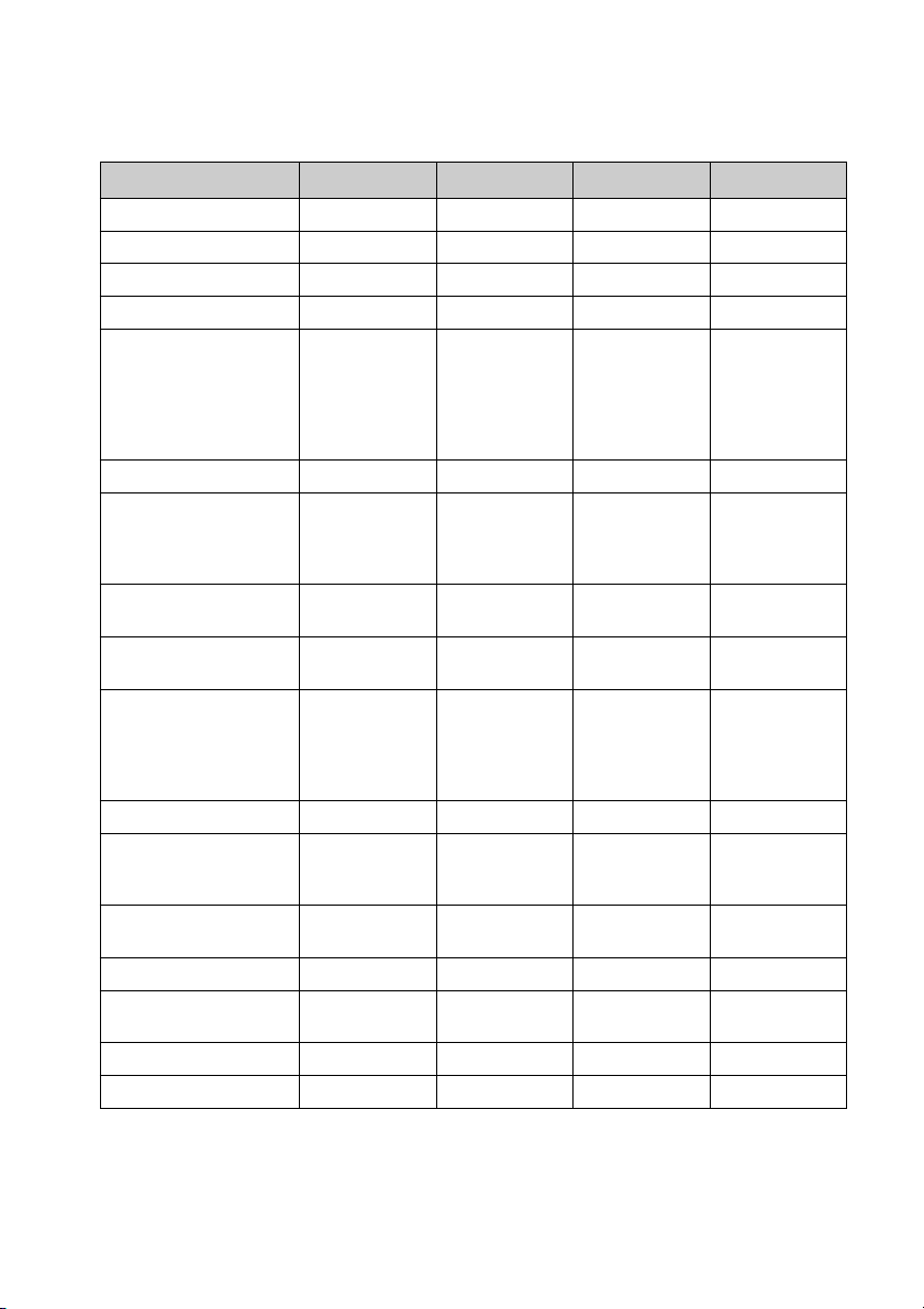
2.1 Technical data
FRIAMAT
®
FRIAMAT®E FRIAMAT®L FRIAMAT®LE
Input voltage range AC 200 V.-. 260 V AC 200 V.-. 260 V AC 200 V.-. 260 V AC 200 V.-. 260 V
Frequency range 44 Hz... 66 Hz 44 Hz... 66 Hz 44 Hz... 66 Hz 44 Hz... 66 Hz
Current consumption AC 16 A max. AC 16 A max. AC 16 A max. AC 16 A max.
Power 3.5 kW 3.5 kW 3.0 kW 3.0 kW
Generator rated output 1~
d20 - d160 AC 2.4 kW AC 2.4 kW AC 2.4 kW * AC 2.4 kW *
d180 - d630 AC 4.0 kW AC 4.0 kW
(mechanical governor)
d180 - d630 AC 4.0 kW AC 5.0 kW
(electronic governor)
Equipment fuse 16 A slow acting 16 A slow acting 16 A slow acting 16 A slow acting
Casing Enclosure class Enclosure class Enclosure class Enclosure class
IP 54 DIN 40 050 IP 54 DIN 40 050 IP 54 DIN 40 050 IP 54 DIN 40 050
Protection class I Protection class I Protection class I Protection class I
DIN 57 700 DIN 57 700 DIN 57 700 DIN 57 700
Connection cable 5 m with 5 m with 5 m with 5 m with
contoured plug contoured plug contoured plug contoured plug
Fusion cable 4 m with Ø 4 mm 4 m with Ø 4 mm 4 m with Ø 4 mm 4 m with Ø 4 mm
fittings plug fittings plug fittings plug fittings plug
Bar code Code 2/5 Code 2/5 Code 2/5 Code 2/5
interleaved to interleaved to interleaved to interleaved to
ANSI HM 10.8M - ANSI HM 10.8M - ANSI HM 10.8M - ANSI HM 10.8M 1983, ISO CD 1983, ISO CD 1983, ISO CD 1983, ISO CD
13950/08.94 13950/08.94 13950/08.94 13950/08.94
Working temperature range -20 °C ... +50 °C** -20 °C ... +50 °C** -20 ° C ... +50 °C** -20 °C ... +50 °C**
Fusion current monitoring Short circuit 110 A Short circuit 110 A Short circuit 110 A Short circuit 110 A
Open circuit Open circuit Open circuit Open circuit
0.25 x I
N
0.25 x I
N
0.25 x I
N
0.25 x I
N
Printer interface Parallel - Parallel -
(D-Sub 25) (D-Sub 25)
Fusion voltage max. AC 48 V max. AC 48 V max. AC 48 V max. AC 48 V
Dimensions 370x280x480 mm 370x280x480 mm 350x260x450 mm 350x260x450 mm
W x D x H
Weight 19 kg 19 kg 14 kg 14 kg
Weight with transport box 23 kg 23 kg 18 kg 18 kg
*: The FRIAMAT®L / LE is only suitable for domestic connections and distribution pipes up to
d110, plus saddle components of all sizes
** : When fusing fittings from other manufacturers always take heed of the details given on the
working temperature range.
9
2.2 Transport / storage / despatch
Your FRIAMAT® model is delivered in a transport box. There are no particular
requirements for unpacking, or for (temporary) storage in the transport box.
Storage temperature - 20 °C to + 70 °C
WARNING ! Do not damage the front face of your FRIAMAT® model !
Always despatch in the transport box.
2.3 Setting up / connection
If protected from rain and wet your FRIAMAT® model can be set up and
operated out of doors.
- Set up the FRIAMAT® on level ground (as near horizontal as possible).
- Ensure that generator is fused with a 16 A minimum (slow acting) fuse.
- Plug the mains plug into the mains socket or connect to the generator.
- If necessary use an extension cable, ensuring that the cross section is
adequate (see section 2.1 “Technical Data”).
- Always comply with the operating instructions for the generator.
WARNING ! Always unroll the cable before use
2.4 Putting into service
WARNING ! Charring ! Dirty contacts can char the plug.
The contact surfaces of the fitting and the fusion plug must always be clean.
- Remove any existing deposits thoroughly
- Protect the plug from contamination, replacing it if necessary
- Check the fusion plugs and contact sockets on the fitting for dirt, and only
then make the connection
10
3. Basic Settings
3.1 Explanation of the function buttons
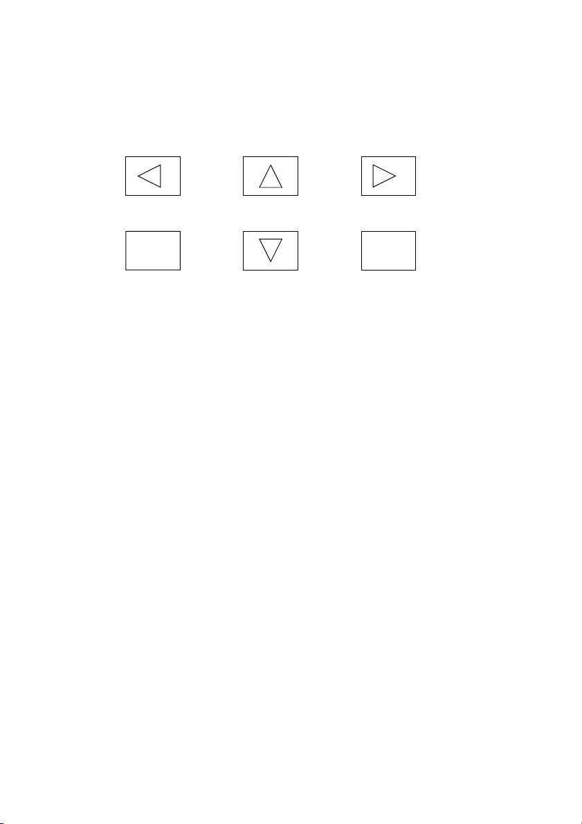
The fusion units of the FRIAMAT® Family have 6 function buttons. Please take
note of the diagram below and the basic explanation of the buttons,
START STOPINFO
SET RESMENU
START: The START button is green in colour. It is used to start a fusion
process, to confirm messages and to call up / select menu functions.
The START button also moves the cursor in the display to the left
when entering characters (e.g. entering notes, date).
STOP: The STOP button is red in colour. It is used to cancel a fusion
process, in some menus to select menu functions and generally to
end menu functions. The STOP button also moves the cursor in the
display to the right when entering characters (e.g. entering notes,
date).
INFO: The INFO button is yellow or grey in colour depending on the
model. It is used to call up current information (voltage / frequency,
date / time, ambient temperature, fusion operator, language) or to
scroll through the individual menus. When entering characters (e.g.
entering notes, date) the setting of the required character is made
with the INFO button.
SET: The SET button is grey in colour. It is used to save settings.
MENU: The MENU button is yellow or grey in colour depending on the
model. It is used to call up the main menu and to scroll through the
individual menus. When entering characters (e.g. entering notes,
date) the setting of the required character is made with the MENU
button.
RES: The RES button is grey in colour. It is used to cancel an input
process.
11

3.2 Date and time
There are two ways of setting date and time.
1. Through the main menu:
Go into the main menu by pressing the MENU button. Now press the
MENU button as many times as it takes for the “Set Date / Time” setting
menu to appear in the display. To set the date / time press the START
button. “FRIAMAT” and the designation of your model will appear in the
top line of the display, whilst the date and time will appear in the bottom
line. The first character will flash. With the INFO / MENU button you can
move one day forward / back. With the START / STOP button you can
move left or right. With the SET button you can confirm and save the new
Date / Time, and with the RES button you can break off without saving.
After pressing the SET or RES button, press the STOP button at the end to
cancel the menu selection.
2. Reading in the TIMER bar code
“FRIAMAT” and the designation of your model will appear in the top line of
the display, whilst the date and time will appear in the bottom line. The first
character (Day) will flash. With the INFO / MENU button you can move one
day forward / back. With the START / STOP button you can move left or
right. With the SET button you can confirm and save the new Date / Time,
and with the RES button you can break off without saving.
FRIAMAT
01.Jul 1999 14:34
3.3 Setting the signal volume
Go into the main menu by pressing the MENU button. Now press the MENU
button as many times as it takes for the “Signal Volume” setting menu to
appear in the display. To set the signal volume press the START button.
“Signal Volume” will appear in the top line of the display, whilst “loud” will
appear on the left in the bottom line and “quiet” on the right. By pressing the
START / STOP button you can adjust the signal volume to loud / quiet. Press
the STOP button at the end to cancel the menu selection.
12

Signal volume
yes continue End
Signal volume
loud quiet
3.4 Setting the language
Go into the main menu by pressing the MENU button. Now press the MENU
button as many times as it takes for the “* Language *” setting menu to
appear in the display (Meaning of the star : See IMPORTANT note in this
section). To set the language press the START button. “* Language *” will
appear in the top line of the display, whilst the actual language set will appear
in the bottom line. Two stars will flash on the right and left to show that you
are in the language setting menu. To change the language select the language
you require with the INFO / MENU button. Press the SET button to end and
save the settings. You can press the RES button to end without saving. Press
the STOP button at the end to end the menu selection.
* Language *
yes continue End
* Language *
* German *
IMPORTANT ! The setting of the language only refers to the one shown
in the display. The language of the documentation
(Report) remains English
IMPORTANT ! In the language setting menu two stars appear, left and
right, in the upper line. These are used to allow the
language setting menu to be recognised when for
example the language has accidentally been set wrongly.
13

4. Operation
4.1 Construction / components
The electronics in your FRIAMAT® model are housed in a splash-proof
casing. The carrying frame is also used to hold the cables. The fusion units of
the FRIAMAT® Family are designed for a maximum fusion voltage of 48 V. The
supply and fusion voltage are isolated from each other by a safety transformer.
4.2 Functional principles
Only electrofusion fittings with a bar code can be fused with the fusion units
of the FRIAMAT® Family : Each fitting is assigned a sticker with a bar code.
This contains the information to ensure that fusion is carried out properly. The
computerised command system of your FRIAMAT® model:
- is completely automatic in regulating and checking the metering of the
electrical power
- determines the fusion time depending on the ambient temperature. The
temperature probe in the fusion cable continuously determines the ambient
temperature.
4.3 Fusion operating procedure
So that the FRIALEN Safety Fittings and the FRIAFIT Sewage Fittings will be
properly processed it is essential to adhere to the FRIALEN operating
instructions.
The same applies to fittings from other manufacturers.
4.4 Preparation
IMPORTANT ! Unroll the cable completely !
This applies to mains, fusion and, if applicable, extension
leads. The contact surfaces of the fitting and of the
fusion plugs must be clean; dirty contacts can cause
overheating and charring of the plug. If necessary remove
any existing deposits cleanly
14

Always protect the plug from contamination. If there is a
deposit which cannot be completely removed, the fusion
plugs must be replaced.
- Prepare the fitting and pipes for fusion in accordance with the assembly
instructions
- Ensure that the contact pins on the fitting are accessible for connection of
the fusion plugs
- Connect up the power supply (mains or generator)
- If using a generator start it up first and allow to warm up for 30 seconds
- Switch on the master switch (1)
- Connect the fusion plugs to the contact pins on the fitting
4.5 Reading in the bar code
IMPORTANT ! It is not acceptable to read in the bar code label from
another sort of fitting instead. After ending the read-in
process the reader wand must be replaced in the reader
wand pouch immediately to avoid damage and contamination to the tip of the wand.
If there is a bar code label stuck onto the fitting this should always be used.
If the bar code label on the fitting being fused is illegible due to damage,
an identical fitting from the same manufacturer with a legible bar code
label should be used.
Hold the reader wand slightly slanting and slightly inclined (like a pencil) and
place it on the fitting in front of the bar code. Now move the reader wand
quickly across the whole label and a little beyond. The reading can be done
from left to right or from right to left. When this has been done correctly the
machine will confirm it with a signal tone. If the reading in is not successful
first time try again, if necessary at a different angle or speed.
15

4.6 Starting the fusion process
IMPORTANT ! If there is a malfunction in the fusion process hot molten
PE can be expelled in rare cases.
So:
Keep at a safe distance of at least 1 m from the fusion
point during the fusion process ! Do not connect any
other equipment during the fusion process !
The fusion process can be broken off at any time by pressing the STOP
button. When the fused area has cooled down (and the source of the fault
eliminated if necessary) the fusion process can be repeated (depending on
the fitting manufacturer; please comply with the instructions for use from the
fitting manufacturer in question).
Operating steps: (see also the visual representation on the next page):
1. Press the START button to initiate the fusion process
2. If applicable confirm the display “Pipe processed ?” with the START
button. Next there will be an automatic display of the ambient temperature
and a resistance check on the connected fitting. The fusion process will
start. In the display you can follow the duration of the fusion process (the
complete fusion time will be displayed and counted down to zero in
seconds).
3. Display “End of fusion” means: fusion process finished, ready for the next
fusion. The displays “t:” and “tc:” mean required and actual fusion time
and these must agree.
4. Make a note of the fusion parameters onto the pipe / fitting. This will also
avoid fusing twice
5. To initiate a new fusion process press the START button.
16

FRIA MON 63 mm
START Infotext
FRIA MON 63 mm
Pipe processed ?
End of fusion
t: 53 s tc: 53 s
4.7 Display voltage and frequency
Before or after the fusion: To display the voltage and frequency press the
INFO button. The STOP button will take you back to the basic setting.
During fusion: Pressing the INFO button will display the voltage and frequency,
after 3 seconds the unit will automatically go back to the basic setting.
Voltage: 221.3 V
Frequency: 50.01 Hz
WARNING ! Your FRIAMAT® model is designed for an input voltage
range of 200 - 260 volts. If you are working in the range
from 150 - 200 volts or 260 - 320 volts the actual voltage
and frequency will automatically appear on the display.
You can ignore this warning note by pressing the STOP
button and carry on working but there is a risk that
you will damage the electronics of your FRIAMAT® model.
If the input voltage range is under 150 volts or above
320 volts the actual voltage and frequency will likewise
appear on the display. In this case, however, the warning
indication will remain until you have regulated the input
voltage back into the recommended range and have
acknowledged with the STOP button.
17

5. Auxiliary function (only for documentation units)
5.1 Documentation
Your FRIAMAT® model is supplied with the documentation deactivated
(switched off). The “Documentation” function is used to save the technical
fusion parameters. These can in each case be assigned to a commission
number and/or to an operator pass.
5.1.1 Switching on
This function is activated or deactivated by reading in a DOCUMENTATION
bar code (see plastic card in the accessories pouch). When the function is
activated the display will show the sequential number on the left and the
number of fusions which can still be stored on the right (and if applicable,
above these the appropriate commission number.)
FRIAMAT
2 ➔ Code 499
5.1.2 Switching off
The DOCUMENTATION function can be deactivated by reading in the
DOCUMENTATION bar code again. The safety question of whether this is
required can be acknowledged by pressing the START button or rejected by
pressing the STOP button (breaking off with the STOP button will bring about
a return to the previous state).
Switch off
documentation ?
18

5.2 Operator’s Pass
IMPORTANT ! The operator pass can only be read in with the documen-
tation switched on
Your FRIAMAT® model can be set for use with an operator pass by reading in
the bar code from an operator pass. The operator pass can be ordered from
FRIATEC. When a user code has been read in for the first time all fusions
which are then carried out will be saved under the code for this operator
pass. If another operator pass is read in your FRIAMAT® model will be
switched over to suit.
Your FRIAMAT® model can be cleared for use without an operator pass by
reading in the USER OFF bar code (see plastic card in the accessories
pouch). The question “Deactivate operator?” then appears. This can be
confirmed by pressing the START button or the process can be broken off by
pressing the STOP button.
IMPORTANT ! By means of the operator pass your FRIAMAT® model
can be blocked to protect it from unauthorised use. .
After reading in the current operator pass again the
query will appear “Block the unit?”. This can be confirmed
by pressing the START button or the process can be
broken off by pressing the STOP button. Your FRIAMAT
model will be automatically blocked when the code for an
operator pass is on file and time-wise a change of date
takes place i.e. your FRIAMAT® model will be blocked on
the next day.
®
Read in
operator
Block the
unit ?
Deactivate
operator ?
19

In both cases (manual or automatic blocking) the note “Read in Operator” will
appear in the display. Your FRIAMAT® model can be cleared for use by
reading in an operator pass
5.3 Commission Numbers
For simple administration of up to 20 different commission numbers your
FRIAMAT® model has a commission number specification menu.
5.3.1 Specifying and saving a commission number
Go into the main menu by pressing the MENU button. Now press the MENU
button as many times as it takes for the “commission no.” setting menu to
appear in the display. To get into the “Change/Specify commission nos.”
setting menu press the START button. By pressing the STOP button you will
go into the specification setting menu in which you can enter and save up to
20 commission nos. If you press the START button the current commission
no. will appear. The first character of the commission no. will flash. This can
be increased by pressing the INFO button or decreased by pressing the
MENU button. With the START / STOP button you can move left or right
within the commission no. With the SET button the commission no. set will be
saved and taken into the Specification Menu, and with the RES button you
can break off the process without saving.
Another method for getting into the “Change/Specify Commission Nos.”
setting menu is to read in the COMMISSION CODE (see plastic card in the
accessories pouch).
Commission No.
Change Specification
Commission No.
New Selection Delete
Commission No.
12 Dossenheimer Way
20

5.3.2 Selecting saved commission numbers
As described in Section 5.3.1, go into the “Change/Specify commission
nos.” setting menu.
By pressing the STOP button you will go into the commission no. specification
menu. If you press the INFO / MENU button the stored commission nos. will
be displayed.
The displayed commission no. is selected by pressing the START or SET
button. The process can be broken off using the STOP or RES button.
Pressing the STOP button again will take you back to the basic setting.
Commission No.
New Selection Delete
5.3.3 Deleting saved commission numbers
As described in Section 5.3.1, go into the “Change/Specify commission
nos.” setting menu. By pressing the STOP button you will go into the
commission no. specification menu. If you press the STOP button you will go
into the Deletion menu.
The displayed Commission No. will be deleted from the commission no.
specification menu by pressing the START button. Pressing the STOP button
will display the next commission no. The fusions which have been saved
under this commission no. will be retained together with the commission no.,
but the commission no. will no longer be available in the commission no.
specification menu.
To leave the Deletion menu press the STOP button as many times as it takes
to get back to the basic setting.
Commission No.
12 Dossenheimer Way
21

5.3.4 Altering currently set (activated) commission numbers
As described in Section 5.3.1, go into the “Change/Specify commission
nos.” setting menu.
After you press the START button the currently set commission no. will
appear. The first character will flash. This can be increased by pressing the
INFO button or decreased by pressing the MENU button. With the START /
STOP button you can move left or right within the commission no. With the
SET button the commission no. set will be saved, and with the RES button
you can break off the process without saving. By pressing the STOP button
again you can go back to the basic setting.
IMPORTANT ! The altered commission no. will not be available in the
commission no specification menu.
Commission No.
12 Dossenheimer Way
5.3.5 Deactivating Commission Nos.
The “Commission No” option will be deactivated by reading in the
COMMISSION OFF CODE (see plastic card in the accessories pouch).
FRIAMAT
2 ➔ Code 498
5.4 Info-text
With the documentation switched on there is a facility to assign an individual
additional text (2x16 characters) to each individual fusion process in the
report. After reading in the fitting bar code press the INFO / MENU button.
The last text entered will appear. The first character will flash. This can be
increased by pressing the INFO button or decreased by pressing the MENU
button. With the START / STOP button you can move left or right within the
Info text. With the SET button the Info-text set will be saved and with the RES
button you can break off the entry process.
22

FRIA MON 63 mm
START Infotext
Kuntz Generator
Type 4500 xs
IMPORTANT ! The additional text has to be newly entered for each
fusion as otherwise no text will appear in the report. If the
START button is pressed directly after reading in the
fitting bar code no additional text will be appended to the
fusion.
5.5 Fusion Report
5.5.1 Print / delete the whole content of the memory
IMPORTANT ! Only printers with a parallel interface can be used. No
printers must be connected during the fusion process.
The fusion report stored in the memory can be printed out. For this the printer
or the Memory Box (optional) has to be connected to the fusion unit. The
printer must be set to “ON-LINE”.
Go into the “Print” setting menu via the Main Menu. Alternatively you can get
into this menu by reading in the PRINT code (see plastic card in the
accessories pouch). After this there will be a query on whether individual, all
or no fusions should be printed out. A complete print-out arranged in
commission number order is started by pressing the START button. A new
page is started for each commission number.
When the complete print-out has finished there will be a query as to whether
the report memory should be deleted. If you want to delete all data press the
START button: the query “Are you sure?” will appear.
23

IMPORTANT ! If the START button is pressed the data will be irretrievably
deleted ! If the STOP button is pressed the data will not
be deleted !
Print
All None Selection
Print
All None Selection
Delete
Are you sure ?
5.5.2 Printing out and deleting individual commission numbers
Go into the “Print” setting menu as described in Section 5.5.1. Pressing the
STOP button will display the first commission number. The commission
number displayed can be printed by pressing the START button and then the
query will appear on whether the data is to be deleted. Pressing the START
button will delete the data, pressing the STOP button will bypass the delete
function and the next commission no. will be displayed. This procedure can
be broken off with the RES button.
24
Print
All None Selection
12 Dossenheimer Way
Print Next
12 Dossenheimer Way
Delete Next

5.5.3 Deleting data without printing out the reports.
Go into the “Print” setting menu as described in Section 5.5.1. By pressing
the INFO button bypass the Print Menu and go directly into the Delete Menu.
The deletion of all or individual data is carried out as already described in
Section 5.5.1. and 5.5.2.
Print
All None Selection
Delete
All None Selection
12 Dossenheimer Way
Delete Next
6. Maintenance / taking out of service
We recommend that you have your FRIAMAT® model serviced once a year
(see list of all authorised Service Stations in section 8.2.). Include all
connection adapters for checking at the maintenance intervals.
6.1 Warranty
The warranty period for the fusion units of the FRIAMAT® Family is 24 months
provided that your FRIAMAT® model undergoes a paid service within the first
14 months. Otherwise the warranty period will be 12 months.
6.2 Care and Maintenance instructions
WHAT ? WHEN ? WHO ?
Clean the reader wand and Daily Operator
check for damage
Check the function Weekly Operator
Clean the contacts Weekly Operator
Factory Maintenance Annually Authorised Service Centres
(see section 8.2)
25

6.3 Checking the reader wand
If the reading is not confirmed after reading in a bar code several times
the reader wand can be checked by reading in the TEST code (see plastic
card in the accessories pouch). “TEST CODE” will appear in the display for
4 seconds.
6.4 Taking out of service
IMPORTANT ! The fusion units of the FRIAMAT® Family contain various
components which make it necessary to ensure that it is
disposed of properly. Your FRIAMAT® model can be
disposed of at the factory or at one of the Authorised
Service Centres
7. Operating faults
7.1 Faults when reading in the bar code
If the reading in is not confirmed by an acoustic signal the reader wand
should be checked for dirt or physical damage. If the reader wand is
defective there is still the facility to carry out the fusion using the Emergency
Input Mode (see below).
7.2 Emergency Input
Go into the “Emergency Input” setting menu via the Main Menu. “Emergency
Input” will appear in the top line of the display, whilst in the bottom line you
will see “Yes” on the left, “Continue” in the centre and “End” on the right.
When the START button is pressed “Code” and 24 characters will appear,
with the first character flashing. This can be increased by pressing the INFO
button or decreased by pressing the MENU button. With the START / STOP
button you can move left or right within the Emergency Input menu. The
figures to be entered should be read off the bar code of the fitting being
fused. After entering the numbers for the bar code you have to confirm the
entry by pressing the SET button - by pressing the RES button you can break
off the process. The fusion process is started by pressing the START button.
Code: 36 18 09 01 06
38 35 08 99 05 47 00
26

7.3 Overheating
If used continuously for long periods your FRIAMAT® model could overheat.
To avoid damage to the unit a temperature monitor has been fitted, and on
the basis of this your FRIAMAT® model will calculate, before the fusion
process, whether the temperature rise anticipated due to the fusion process
is acceptable. If the calculated temperature does not lie within the permitted
range the message “Allow the unit to cool down” will appear on the display.
Since the power consumption of various electrofusion fittings will differ there
may be a possibility of fusing a different fitting.
7.4 Fusion interruption
If the fusion is broken off because, e.g. the power supply has been interrupted
during a fusion run, the fusion can be repeated after removing the cause of
the problem and after allowing the fitting to cool down completely (this is
dependent on the fitting manufacturer; always comply with the instructions
for use from the fitting manufacturer in question).
27

7.5 Fault messages / Warning messages
If irregularities occur during the fusion process then your FRIAMAT® model
will show suitable fault messages in the display
Fault messages
No. Text in display Meaning / causes Remedy
1 - - 2 Temperature Ambient temperature If necessary set up a tent
outside range outside the permitted
range
3 Resistance Electrical resistance of Check contacts for firm
outside tolerance the fitting is outside seating / dirt
the tolerance Clean contacts if necessary
If necessary replace fitting
4 Fitting winding Short circuit in the wire Replace fitting, send in
short circuit winding of the fitting for examination
5 Fitting winding Current flow interrupted Check the connection of
open circuit the fusion plug on the fitting.
If OK replace the fitting and
send in for examination
6 Voltage outside Unacceptable deviation Inform Authorised Service
tolerance of the fusion voltage Centre
7 Fault in the Malfunction in the Make a note of the fault
a..z operating system FRIAMAT® hardware or classification (a...z) and
software inform Authorised Service
Centre
8 Mains voltage Mains voltage outside Extension cable too long or
outside range the permitted range its cross section too small.
during fusion Check the voltage and
connection conditions of
the generator
9 Frequency outside Frequency outside the Check the frequency of the
range permitted range during generator voltage
fusion
10 Fusion interrupted Fusion broken off by -
pressing the STOP button
28

More Fault messages
No. Text in display Meaning / causes Remedy
11 - - -
12 - - 13 Mains failure Supply voltage inter- Check connection
rupted or too low conditions
14 - - -
15 Power rating Power consumption of -
exceeded the fitting exceeds the
rating of the FRIAMAT
®
An example of what is shown on the display:
Fault 3 INFO ?
Resistance
outside tolerance
By pressing the INFO button you will get information on the fault in plain
language
Warning messages :
Text in display Instruction / Remedy
Faulty or damaged bar code Use a new bar code from an identical
fitting or correct the manually entered code
Memory full Print out the log
Memory empty If the memory is empty no printout
is possible
Printer not ready Check whether the output device (printer,
Memory Box, PC with FRIATOOL II) is
connected correctly
29

More warning messages :
Text in display Instruction / Remedy
Let the unit cool down Protective function which prevents
overheating of the equipment. Switch off
the unit and allow it to cool down until
the warning message is no longer
displayed after switching on.
Service date exceeded Inform Authorised Service Centre.
Have the equipment serviced.
Voltage .... V; Frequency .... Hz Readjust generator then acknowledge
with the STOP button (See Section 4.7)
No text, just a continuous acoustic Supply voltage too low
tone
N.B. Double fusion If a fitting is to be fused twice the contact
plugs of the fusion unit must be pulled off
the fitting after the first fusion and the
fitting allowed to cool down (see the
instructions for use from the fitting
manufacturer)
8. Appendix
8.1 Recommended accessories (options)
- Memory Box to transfer fusion data
- FRIATOOL II for electronic processing of the fusion data
- Operator pass
- Scanner
- Remote start pass
- Fusion cable extension
- Infrared remote control
30

8.2 Authorised Service Centres world-wide
FRIATEC AG
Niederlassung Mannheim
Steinzeugstraße
D-68229 Mannheim
Tel.: 0621 / 486-1533
Fax: 0621 / 486-2030
FRIATEC AG Bohnenschäfer
Niederlassung Wittenberg Westberger Weg 86a
Waldstraße D-59065 Hamm
D-06886 Wittenberg Tel.: 0 23 81 / 6 42 43
Tel.:0 34 91 / 61 53 22 Fax: 0 23 81 / 6 08 41
Fax: 0 34 91 / 61 53 12
Axel Jülicher GmbH KS - Kirsch
Hahnenstraße 19 Schweißtechnik
D-28309 Bremen Reetzerstraße 12
Tel.: 04 21 / 87 8-0 D-31515 Wunstorf
Fax: 04 21 / 87 8 11 Tel.: 0 50 31 / 90 96 23
Fax: 0 50 31 / 7 72 37
Hansen & Reinders DIWA Schweißtechnik GmbH
GmbH & Co. KG Heidelberger Straße 11
Manderscheidtstraße 48 D-01189 Dresden
D-45141 Essen Tel.: 03 51 / 4 01 65 37
Tel.: 02 01 / 89 10 90 Fax: 03 51 / 4 01 65 17
Fax: 02 01 / 21 62 10
Friedrich Rütz Meyer Elektronic
Reinbeker Redder 102 Elmendorfer Straße 9-10 A
D-21031 Hamburg D-26160 Bad Zwischenahn
Tel.: 0 40 / 7 39 21 60 Tel.: 04 40 3 / 97 15-0
Fax: 0 40 / 7 30 40 41 Fax: 04 40 3 / 97 15 17
FRIATEC GmbH FRIATEC S.A.R.L.
Birostraße 13 Z.A. La Grande Borne
A-1230 Wien F-77140 Darvault/Nemours
Tel.: 00 43 / 61 057 Tel.: 00 33 1 64 45 23 33
Fax: 00 43 / 61 057 5 Fax: 00 33 1 64 45 23 20
31

FRIATEC S.A.U. IBERGAS-Comercio
Cuesta del Rio, s/n Cabo Ruivo
E-28860 Paracuellos del P-1800 Lisboa
Jarama/Madrid Tel.: 00 35 1 1 8 68 72 06 18
Tel.: 00 34 9 6 58 22 50 Fax: 00 35 1 1 8 68 45 71
Fax: 00 34 9 6 58 27 53
TUMAB Scanotherm
Box 50 Møllebakken 4
S-26821 Svalöv DK-6091 Bjert
Tel.: 00 46 4 18 16 385 Tel.: 00 45 75 57 29 66
Fax: 00 46 4 18 41 193 9 Fax: 00 45 75 57 24 95
VIGOTEC SA FRIATEC B.V.
Industrielaan 15 Steenpad 5
B-1740 Ternat NL-4797 Willemstad
Tel.: 00 32 2 58 27 11 0 Tel.: 00 31 168 47 36 51
Fax: 00 32 2 58 22 0 32 Fax: 00 31 168 73 2 00
FRIATEC s.r.o. FRIATEC Sp.z.o.o.
V Korytech 23 ul. Gdanska 40
CZ-10600 Praha 10 PL-70660 Szczecin
Tel.: 00 42 0 2 72 76 03 36 Tel.: 00 48 91 46 23 245
Fax: 00 42 0 2 72 76 45 69 Fax: 00 48 91 46 23 245
FRIATEC s.r.o. FRIATEC-KFT
Nitrianska 2 To 4.3.
SK-91700 Trnava H-2045 Torokbalint
Tel.: 00 42 18 05 55 14 626 Tel.: 00 36 23 33 78 41
Fax: 00 42 18 05 55 13 307 Fax: 00 36 23 33 78 42
MIVA spol. S.r.o. FRIATEC S.R.L.
Teplicskà cesta 10 Via Aldo Moro, 10
SK-05201 Spisska Nova ves I-20080 Carpiano
Tel.: 00 42 96 54 21 590 Tel.: 00 39 2 98 50 90 34
Fax: 00 42 96 54 21 590 Fax: 00 39 2 98 85 90 33
FRIATEC Incorporated FRIATEC Plasmec Pty. Ltd.
426 Fairforest Way 24 Appel Road
Greenville, SC 29609/USA Kramerville, Sandton
Tel.: 18 64 28 68 800 RSA-2144 Wendywood
Fax: 18 64 23 42 050 Tel.: 00 27 11 444 13 21
Fax: 00 27 11 444 28 40
32

IPS Pty. Ltd. ETA Plus Ltd.
Locked Bag 106 49 Cottle Park Drive
AUS-Kingsgrove NSW 2208 NZ-Lower Hutt
Tel.: 00 61 25 54 39 77 Tel.: 00 64 58 90 145
Fax: 00 61 25 02 25 61 Fax: 00 64 58 90 146
Jar Tai Trading Ltd. STR Marketing Ltee.
8 Lane 402, Ming-Sheng Rd. P.O. Box 98
Taichung / Taiwan Port Louis / Mauritius
Tel.: 00 88 64 32 25 005 Tel.: 00 23 02 12 99 72
Fax: 00 88 65 32 20 911 Fax: 00 23 02 12 99 98
Ukrgasifikazia Yug UAB DS1
3, Pedagogicheskaya Ul. Gedimino g 30
270009 Odessa / Ukraine 4050 Trakai / Litauen
Tel.: 00 38 04 82 68 54 83 Tel.: 00 37 03 85 23 16
Fax: 00 38 04 85 68 40 05 Fax: 00 37 03 85 11 33
Elektrakip Benapartner Sdn Bhd
ul. Kabuschkina 80 No. 25, Jalan TPJ 8/1
BY-220118 Minsk Taman Perindustrian Jaya
Tel.: 00 37 00 17 22 40 95 38 47200 Subang Selangor
Fax: 00 37 00 17 22 45 67 67 Darul Ehsan / Malaysia
Tel.: 00 60 37 54 54 66
Fax: 00 60 37 54 54 67
T S J S U I
Techniques in Safe Jointing Southern Gas Co. Ltd.
Av. General Paz 62 State Life Building No.3
RA-1702 Ciudadela Dr. Ziauddin Ahmed Road No. 318
Buenos Aires 75530 Karachi / Pakistan
Tel.: 00 54 14 88 94 87 Tel.: 00 92 25 73 134
Fax: 00 54 16 57 45 02 Fax: 00 92 25 73 074
Akfel Mühendislik Caldervale Technology Ltd.
Ic Ve Dis. Tic Ltd. Sti Grange Road,
Bagdat Cad. Hasan Amir SK. Batley
Dursoy is Merkezi No. 4/13 GB-WF 17 6LN West Yorkshire
TR-81030 Kiziltoprak Istanbul United Kingdom
Tel.: 00 90 21 64 14 87 78 Tel.: 00 44 19 24 42 25 70
Fax: 00 90 21 64 14 87 80 Fax: 00 44 19 24 42 25 85
33

Plant & Site Ltd. Ferdinand Wehrli
Gatehouse Warehousing Schulgasse 174
2 Harper Lane CH-8215 Hallau
Shenley Tel.: 00 41 / 5 26 81 18 87
GB-Wd7 9 HA, St.Albans Herts Fax: 00 41 / 5 26 81 18 87
United Kingdom
Tel.: 00 44 17 27 82 66 93
Fax: 00 44 17 27 82 27 31
FRIATEC Rheinhütte do Brasil
Av. Manoel Inácio Peixoto 2150
BRA-36770 Cataguases MG
Tel.: 00 55 32 69 46 207
Fax: 00 55 32 69 46 241
34

35

Technical Equipment FRIALEN®/FRIAFIT
®
36
FRIATEC Aktiengesellschaft
Technical Plastics Division
P.O.B. 7102 61 · D-68222 Mannheim
Phone (06 21) 486-0
Fax (06 21) 479196
Internet: http://www.friatec.de
e-mail: info-frialen@friatec.de
A member of GLYNWED Pipesystems
 Loading...