

1
Update: 01.07.2014
EN
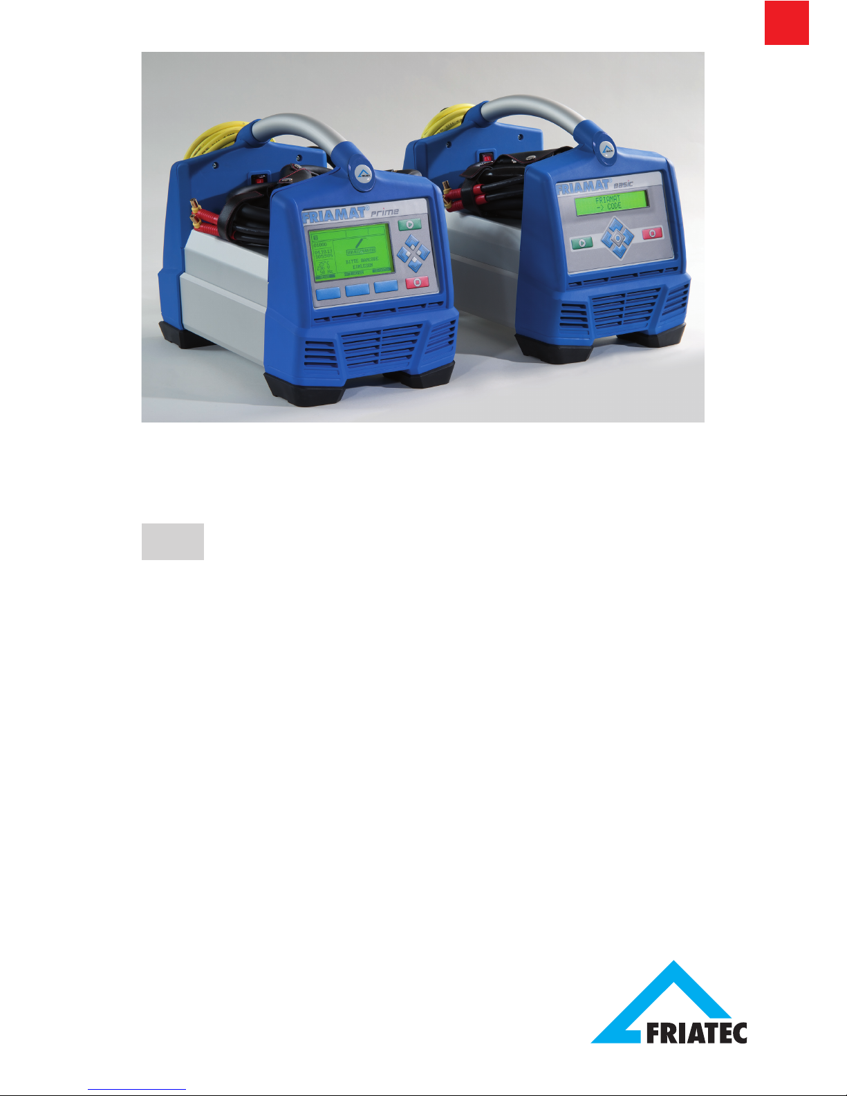
Operating instructions
Electrofusion units
FRIAMAT® Prime
FRIAMAT® Basic
FRIAMAT
®

2
Stand/Update: 01.07.2014
EN
Contents Page
1 Preliminary remarks 6
1.1 Safety instructions and hints 6
1.2 Intended use 6
2 Safety 7
2.1 Functional reliability 7
2.2 The operator’s obligations 7
2.3 Sources of danger 8
2.4 Mains operation 8
2.5 Generator operation 9
2.6 Extension cable 10
2.7 Opening the device 10
2.8 Safety measures at the installation site 10
2.9 Emergency 10
3 Basic information 11
3.1 Layout/parts 11
3.2 Type plate 11
3.3 Reader wand 12
3.4 Barcode scanner 12
3.5 Protective cap for data interface 13
3.6 Temperature probe 13
3.7 Fan functionality 13
3.8 Signalling devices 14
3.9 Technical details 14
3.10 Automatic activation of maintenance interval 16
3.11 Transport/storage/dispatch 16
4 “Fusion” sequence 16
4.1 Siting, connection, and startup 16
4.2 Reading in the barcode 17
4.3 Starting the fusion procedure 18

3
EN
Stand/Update: 01.07.2014
Contents Page
5 FRIAMAT Basic 19
5.1 Function keys explained 19
5.2 Display symbols explained 20
5.3 “Basic Settings” menu 20
5.4 “Info” menu 21
5.5 “Emergency Input” menu 21
6 FRIAMAT Prime 22
6.1 Function keys explained 22
6.2 Display layout (main screen) 23
6.3 Function key symbols explained 24
6.4 Function status symbols explained 25
6.5 Main window symbols explained 26
6.6 “Basic Settings” menu 26
6.6.1 Documentation 27
6.6.2 Time 27
6.6.3 Date 27
6.6.4 Language 27
6.6.5 Protocol language 28
6.6.6 Volume 28
6.7 “Emergency Input” menu 28
6.8 “Fusion Sequence” menu 28
6.8.1 Commission number 29
6.8.2 Operator pass 29
6.8.3 Info Text 30
6.8.4 Comment 1 30
6.8.5 Comment 2 30
6.8.6 Subcontractor 31
6.8.7 Traceability 31
6.8.8 Pipe Number 31
6.8.9 Pipe Length 31
6.8.10 GPS Data 31
6.8.11 Seam number 31
6.8.12 Scraper tool 31

4
Stand/Update: 01.07.2014
EN
Contents Page
6.9 “Data” menu 32
6.9.1 Transfer 32
6.9.2 PDF 33
6.9.3 CSV 33
6.9.4 Delete 34
6.10 “Info” menu 34
6.11 “Formatting” menu 34
6.12 Fusion options 35
6.12.1 ID Data 35
6.12.1.1 Commission number 35
6.12.1.2 Operator pass 36
6.12.1.3 Serial number 36
6.12.1.4 Seam number 36
6.12.1.5 GPS 1 – 3 37
6.12.2 Traceability Barcodes / Pipe Number / Pipe Length 38
6.12.3 Info Text, Comment 1, Comment 2, Subcontractor 39
6.12.4 Scraper tool 39
6.13 SUPERVISOR 40
6.13.1 Basic Settings 41
6.13.1.1 Documentation 41
6.13.1.2 Time 41
6.13.1.3 Date 41
6.13.1.4 Data Protection 42
6.13.1.5 Maintenance Date 42
6.13.1.6 Mode 42
6.13.1.7 Language 42
6.13.1.8 Emergency Input 42
6.13.1.9 Energy Display 42
6.13.1.10 Volume 42

5
EN
Stand/Update: 01.07.2014
Contents Page
6.13.2 Fusion Sequence 43
6.13.2.1 Traceability 43
6.13.2.2 Info Text 43
6.13.2.3 Comment 1 43
6.13.2.4 Comment 2 43
6.13.2.5 Subcontractor 44
6.13.2.6 GPS Data 44
6.13.2.7 Seam number 44
6.13.2.8 Serial number 44
6.13.2.9 Commission number 44
6.13.2.10 Operators pass 44
6.13.2.11 Pipe Prepared? Display 44
6.13.3 Factory Settings 45
6.13.4 PIN 45
6.13.5 Display (Resistance) 46
7 Warranty/maintenance/disposal 46
7.1 Warranty 46
7.2 Maintenance and care 46
7.3 Disposal 47
8 Error messages / warnings / info 48
9 Annex 51
9.1 Recommended accessories (options) 51
9.2 Authorised service stations 51
9.3 Updates to these operating instructions 51

6
Stand/Update: 01.07.2014
EN
1 Preliminary remarks
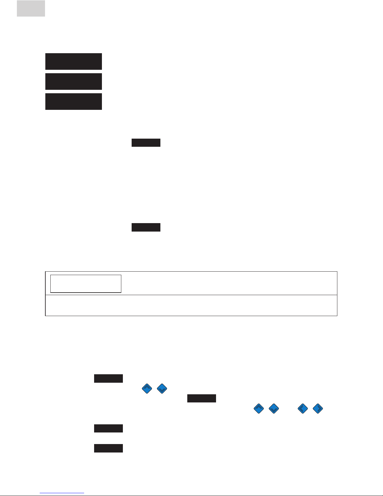
1.1 Safety instructions and hints
In these operating instructions, the following symbols with warnings are used:
Symbol Meaning
WARNING!
Danger to people.
Failure to comply can result in death or serious injury.
CAUTION!
Danger to people.
Failure to comply can result in minor or moderate injury.
NOTE
Danger to objects.
Failure to comply can result in objects damage.
INFORMATION
Application hints and other useful information.
Failure to comply can not result in personal inury or
objects damage.
1.2 Intended use
FRIAMAT fusion units are designed to apply a maximum fusion voltage of
48 V on the following:
•FRIALEN
®
safety fittings with HDPE pressure pipes (SDR 17-7),
•derFRIALEN® XL large pipe installations with HDPE pressure pipes
(SDR 17-7), and
•FRIAFIT® sewage fittings with HDPE sewage pipes (SDR 17-33).
FRIAMAT fusion units can also be used on fittings from other manufacturers
when these components bear a 24 digit barcode complying with ISO
13950:2007-03. The power ratings and technical data of both the fittings and
the FRIAMAT fusion unit must be observed (see also Section 3.9 “Technical
data”).
Intended use also includes adherence to:
•alloftheinstructionsintheseoperatinginstructions,
•thegeneralandspecicprocessingspecicationsforelectrofusion
fittings, and
•theapplicableaccidentpreventionregulations,theenvironmental
regulations, the statutory rules, the pertinent safety provisions, and
all standards, laws, and directives applying in the country of use.

7
EN
Stand/Update: 01.07.2014
2 Safety
2.1 Functional reliability
FRIAMAT fusion units are state of the art, built in accordance with the requirements under ISO 12176-2 and the acknowledged safety standards and fitted
with the required safety devices. Prior to delivery, FRIAMAT fusion units are
tested for correct and safe functioning. Failure to operate or otherwise use the
equipment properly will pose a danger to:
•thehealthoftheoperator,
•theFRIAMATfusionunitorotherpropertyoftheuser,or
•theefciencyofworkwiththeFRIAMATfusionunit.
Safety considerations forbid the following:
•modicationsandchangestotheFRIAMATfusionunitand
•workingwithFRIAMATfusionunitswithbrokenleadseals.Failingto
observe the above makes all warranty claims void.
2.2 The operator’s obligations
Only trained personnel may work with the FRIAMAT fusion unit. In the work
area, the operator is responsible for all third parties. The owner is obliged:
•tomaketheoperatinginstructionsaccessibletotheoperatorand
•toensurethattheseinstructionshavebeenreadandunderstood.
The operating instructions must be kept at all times at the device’s place
of use (ideally in the mesh pocket on the transport box). They must be
accessible to the operator at all times.
8
Stand/Update: 01.07.2014
EN
2.3 Sources of danger
WARNING!
Electric shock from live parts! Danger of death!
- Never leave the FRIAMAT fusion unit unattended.
- Immediately replace damaged housings, connecting lines, and extension
cables. Stop using the FRIAMAT fusion unit.
- Before all care and maintenance work, pull out the plug connecting the
equipment.
- Maintenance and repair work must be performed by authorised FRIATEC
service stations only.
- Supply FRIAMAT fusion units only with the operating voltage specified on
the ratings plate.
- Fit a residual current protective device (RCD) when this is prescribed.
- Do not remove or otherwise put safety installations out of operation.
- Immediately eliminate identified defects.
WARNING!
Danger of fire and explosion from highly flammable materials and
potentially explosive atmospheres!
- Keep away from flammable liquids and gases.
- Do not use in potentially explosive atmospheres (e.g. in areas where
flammable gases, solvent vapours, or ignitable dusts can accumulate).
- Never leave the FRIAMAT fusion unit unattended.
2.4 Mains operation
Out of doors (building sites), power outlets must be fitted with residual
current protective devices (RCDs). The regulations governing RCDs must be
observed here.
NOTE
Before commencing fusion, check the input voltage. The FRIAMAT fusion unit
is designed for an input voltage range of 190–250 V!
9
EN
Stand/Update: 01.07.2014
2.5 Generator operation
NOTE
Only those generators must be used that have been designed for industrial
use on building sites. The operating instructions for the generator must be
observed!
The use of generators must comply with DVGW work sheet GW308, VDE
0100 Part 728, and the specifications and guidelines applying in the country
of use.
INFORMATION
The rated power output required from the generator depends on the level
needed for the largest fusion fitting, the connection conditions, the ambient
conditions, the generator type, and its control characteristics. Generators from
different series exhibit highly diverse control characteristics. The suitability of
a specific generator, therefore, cannot be safeguarded even when it provides
the required rated power output according to its technical data sheet.
In cases of doubt, e.g. when acquiring new equipment, contact our service
hotline +49 (0)621 486-1533!
Use only those generators that operate with frequencies within 44–66 'Hz.
First start the generator, and let it run for half a minute. If necessary, adjust the
no-load voltage, limiting it to the voltage specified in the technical data. The
generator (mains) fuse must be at least 16 A (slow blow).
NOTE
During fusion, do not operate any other consumer from
the same generator!
On finishing fusion work, first pull out the plug connecting the device to the
generator, and then switch off the generator.
10
Stand/Update: 01.07.2014
EN
2.6 Extension cable
When using an extension cable, make sure it has an adequate conductor
cross section:
•2.5mm
2
up to 50 m in length or
•4mm2 up to 100 m in length.
NOTE
Danger of overheating in the extension cable!
The extension cable may be used only when it has been completely unwound and
stretched out.
2.7 Opening the device
WARNING!
Electric shock from live parts! Danger of death!
- Never open the FRIAMAT fusion unit when it is supplied with operating
voltage!
- FRIAMAT fusion units may be opened only by specialised personnel from
an authorised FRIATEC service station!
2.8 Safety measures at the installation site
The connecting and fusion cables must be protected against sharp edges. Do
not expose the FRIAMAT fusion unit to heavy mechanical loads.
FRIAMAT fusion units are splash proof. They may not, however, be immersed
in water.
2.9 Emergency
In emergencies, immediately set the main switch to OFF, and disconnect the
FRIAMAT fusion unit from the voltage supply.
11
EN
Stand/Update: 01.07.2014
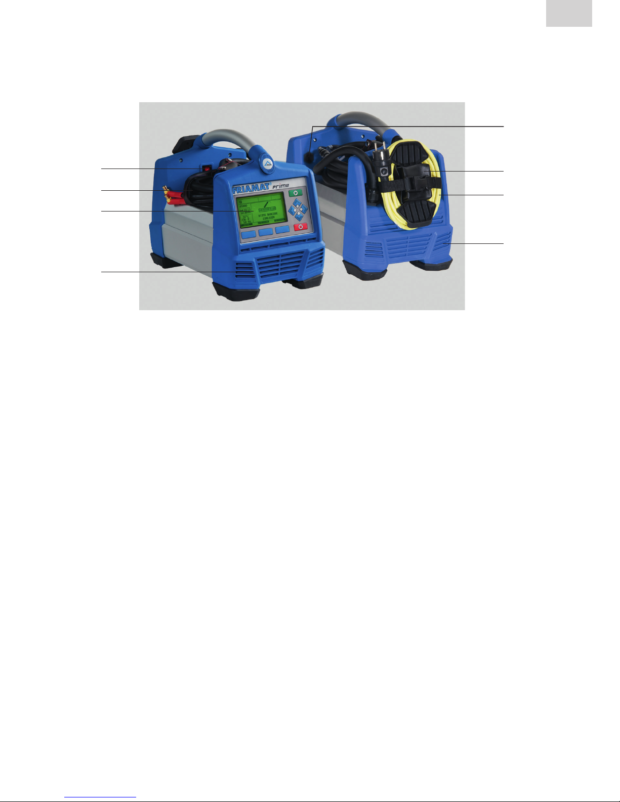
3 Basic information
3.1 Layout/parts
1
2
3
4
6
7
8
5
1 Main switch 4 Ventilation slots (air intake)
2 Fusion cable with reader wand or 5 Data interface with (USB)
barcode scanner protective cap
3 Front foil with display and 6 Adapter bag
function keys (Fig shows 7 Power cable
FRIAMAT Prime) 8 Ventilation slots (air outlet)
3.2 Type plate
The type plate lists the details specific to the FRIAMAT fusion unit and
its unique device number. The type plate is found on the rear side of the
device, under the adapter bag.
12
Stand/Update: 01.07.2014
EN
3.3 Reader wand
To read in fusion barcodes and traceability barcodes, place the reader wand
under a slight angle (like a pencil) in front of the barcode on the fitting. Now
move the reader wand quickly over the whole label and a little beyond. Barcodes can be read in from right to left or vice versa. When the barcode has
been read in correctly, the device emits an acoustic signal to confirm this. If
the barcode cannot be read in the first time, repeat the procedure, this time
under a different angle or at a different speed.
NOTE
Protect the tip of the reader wand from dirt and damage!
The condition of the reader wand tip has a direct effect on the legibility of barcodes.
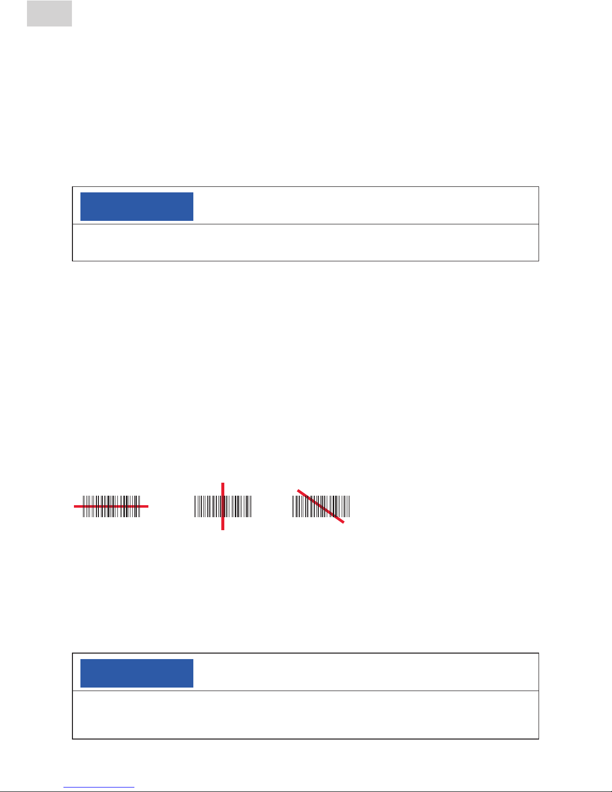
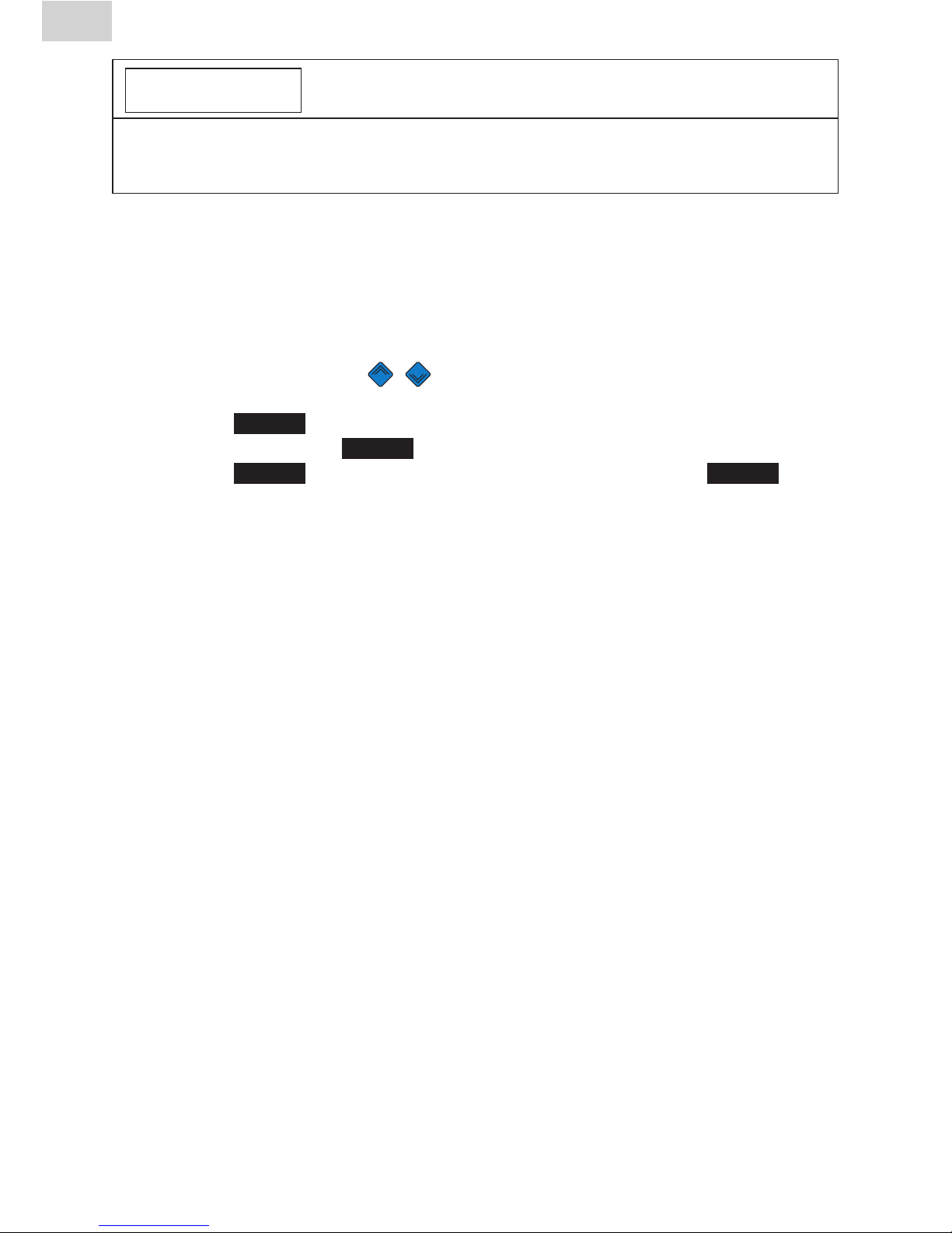
3.4 Barcode scanner
The barcode scanner uses a laser to read in fusion barcodes and traceability
barcodes without physical contact. All you need to do is aim at the barcode
and press the read button. The barcode is scanned by means of a red light
strip that must cross over the whole barcode, whenever possible at the centre. The barcode is not detected properly when the red light strip does not
cross the whole barcode.
The optimal read results are obtained when the scanner is positioned at a
small distance over the barcode.
Good legibility Failed to read Failed to read
Badly printed or slightly damaged barcodes can be read in when the scanner
is placed directly on the barcode and then, with the read button pressed,
moved away. When the barcode is read in successfully, the device emits an
acoustic signal, and a green indicator lamp lights up in the middle of the read
barcode.
NOTE
Protect the reading window from dirt and scratches!
The condition of the reading window has a direct effect on the capabilities of the
FRIAMAT barcode scanner.
13
EN
Stand/Update: 01.07.2014
3.5 Protective cap for data interface
The USB-A port is found directly behind the protective cap. This data interface functions as a service port and, on the FRIAMAT Prime, is also used
to read out and transfer the fusion protocol. The protective cap for the data
interface must be screwed on at all times to prevent contaminants and
moisture from reaching it.
3.6 Temperature probe
FRIAMAT fusion units can be used only on electrofusion fittings bearing a
barcode. When this is read in, the microprocessor controlled FRIAMAT fusion
unit regulates and monitors the supplied energy fully automatically and defines the fusion time as a function of the ambient temperature. This ambient
temperature is continuously measured by the temperature probe on the fusion
cable (silver coloured metal sleeve at the reader wand or scanner bag).
Make sure that both the temperature probe and the fusion fitting are exposed
to the same ambient temperatures. Avoid adverse processing situations, e.g.
where the probe is exposed to intense sunlight and the fitting is in the shade.
The temperature probe must be protected against damage.
3.7 Fan functionality
How the fans function depends on the temperatures measured at the heat
sink inside the FRIAMAT fusion unit. The fans switch ON automatically when
the heat sink reaches a certain temperature. And this not only during, but also
between fusion sessions, or after reactivation, depending on the (previous)
load levels. This safeguards reliable operations in continuous duty and during
fusion on large dimensions.
INFORMATION
Reduce cooling times!
In particular during series fusion work or work on fittings requiring high power
levels, leave the FRIAMAT fusion unit switched ON after each fusion. The fans
can then reduce the heat sink temperature.
14
Stand/Update: 01.07.2014
EN
3.8 Signalling devices
FRIAMAT fusion units confirm certain sequences of operations by emitting an
acoustic signal (1, 2, 3, or 5 beeps). These signals mean the following:
1 beep means: Read barcode confirmed.
2 beeps mean: Fusion procedure ended.
3 beeps mean: Supply voltage too low / too high.
5 beeps mean: Error! See display!
INFORMATION
Adjust the volume!
The volume of these signals can be set to “high” or “low” in the “Basic Settings”
menu. See also Sections 5.3 and 6.2.6.
3.9 Technical details
Technical details* FRIAMAT Prime FRIAMAT Basic
Input voltage range AC 190 V – 250 V
Frequency range 44 Hz...66 Hz
Input current AC 16 A max.
Output 3.5 kW
Generator rated
output for fittings
d20–d160
d180–d900 ~ AC 5.0 kW
Unit fuse 16 A slow blow
Housing international protection IP 54 DIN EN 60529
protection class I DIN EN 60335-1
Connecting cable 5 mm with contoured plug
Fusion cable 4 m with fittings plug, ø 4 mm
Barcode type code 2/5 code 2/5
interleaved according to interleaved according to
ANSI HM 10.8 M-1983 ANSI HM 10.8 M-1983
and ISO CD 13950/08.94 and ISO CD 13950/08.94
code 128 according to
ISO 12176-4

15
EN
Stand/Update: 01.07.2014
*: Specifications subject to change.
**: Fusion work on fittings from other manufacturers must comply with their respective
working temperature ranges!
Technical details* FRIAMAT Prime FRIAMAT Basic
Operating temperature range** -20°C...+50°C**
Fusion current monitoring short circuit 110 A
short circuit 1.70 x IN
interrupt 0.25 x IN
Fusion voltage max DC 48 V
Data transfer interface USB no
Service port USB USB
Documentation of fusion yes no
and traceability data
Protocol formats FRIATRACE no
format, PDF, CSV
Protocol memory 1000 protocols no
Languages Bulgarian, Croatian, Czech, Danish, Dutch,
English, Estonian, Finnish, French, German,
Hungarian, Italian, Latvian, Lithuanian, Polish,
Portuguese, Romanian, Russian, Slovakian,
Slovenian, Spanish, Swedish, Turkish
Dimensions W x D x H 260 x 500 x 340 mm
Weight approx 12.8 kg
Accessories operating instructions, operating instructions,
transport box, transport box
FRIATEC memory stick,
supervisor pass
Overvoltage classification Category II
Certificate/quality CE, ISO 9001, WEEE Reg. No. DE 49130851, RoHS
16
Stand/Update: 01.07.2014
EN
3.10 Automatic activation of maintenance interval
The maintenance interval stored in the FRIAMAT fusion unit (default: 12
months, see also Section 7.2) is not activated automatically until after the first
fusion.
INFORMATION
The leading maintenance date is always shown on the display and may differ
from the details on the service label attached to the FRIAMAT fusion unit!
3.11 Transport/storage/dispatch
The FRIAMAT fusion unit is delivered in an aluminium transport box. This aluminium transport box keeps it dry and protected against moisture. The aluminium box should always be used to transport the device. The temperature
range for storage is -20 °C to +70 °C.
4 “Fusion” sequence
4.1 Siting, connection, and startup
Before every use, you should check that the FRIAMAT fusion unit is not damaged and operates properly within the specifications. All parts must be correctly installed and all conditions fulfilled. Only then can the device operate
properly.
The FRIAMAT fusion unit can be sited and operated out of doors when it is
protected against rain and moisture.
1. The FRIAMAT fusion unit must be sited on level ground.
2. Prepare the fitting and pipes for fusion in compliance with the assembly
instructions.
3. Make sure that the fitting’s contact pins are accessible for connection to
the fusion plugs.
NOTE
Danger of overheating in the cables!
Before use, all cables must always be unwound completely. This applies to the
device, fusion, and extension cables.

17
EN
Stand/Update: 01.07.2014
4. Connect the device to the power supply (mains or generator). To do so,
insert the device’s plug into the socket.
5. If necessary, use an extension cable. Make sure that the conductor cross
section is adequate (see also Section 2.6).
6. When operating with a generator, make sure that it is fused with at least
16 A (slow blow, see also Section 2.6).
7. When operating with a generator, first start the generator and let it warm
up for 30 s.
8. Switch ON the FRIAMAT fusion unit at its main switch.
NOTE
Danger of scorching!
The contact areas on the fusion plugs and fitting must be clean. Soiled contacts can
cause the plug to overheat, damaging it.
• Ifnecessary,wipecleanofanycontaminants.
• Youmustalwaysprotecttheplugsagainstsoiling.
• Whenadeposithasformedthatcannotberemovedcompletely,thefusionplugs
must be replaced.
• Firstexaminethefusionplugsandthetting’sinsertcontactsforsoiling,then
connect them.
9. Connect the fusion plugs to the contact pins on the fitting.
10. The fusion plugs must be attached completely to the fitting’s pins, i.e. over
their whole internal contact length.
4.2 Reading in the barcode
1. Read in the barcode: use exclusively the barcode affixed to or provided
with the contacted fitting.
2. If the barcode label is missing or damaged, you can use the barcode on an
identical fitting from the same manufacturer and the same charge. In cases
of doubt, contact the fitting manufacturer’s hotline.
NOTE
It is forbidden to read in a replacement barcode on a different fitting!
3. Read in the barcode with a reader wand or barcode scanner (see also
Sections 3.3 and 3.4).
4. A correctly read barcode is confirmed with an acoustic signal.

18
Stand/Update: 01.07.2014
EN
INFORMATION
When an acoustic signal is not emitted, examine the reader wand or barcode
scanner for soiling or damage. If necessary, you can also perform the fusion in
emergency input mode (see Sections 5.5 and 6.3)!
4.3 Starting the fusion procedure
CAUTION!
Danger of burning injury!
In rare cases, hot PE melt can exit when the fusion sequence malfunctions. A safety
distance of at least 1 m must be kept from the fusion site.
NOTE
Do not connect any other consumers during fusion!
Youcanstopthefusionprocedureatanytimebypressingthe(STOP)key
. Fusion can be resumed after the fusion joint has cooled completely
(and all causes of the fault have been eliminated). Observe here the processing instructions from the fitting manufacturer.
Operating steps
1. “Pipe Processed?” appears on the display. When applicable, confirm
this with the (START) key or, on the FRIAMAT Prime, the guide key
O.K.
.
2. Press the (START) key to initiate the fusion procedure. The ambient
temperature is measured, and the resistance of the connected fitting determined. Fusion begins. The duration of fusion can be followed on the
display (the seconds are counted up to the final fusion time).
3. “End of fusion” means: Fusion procedure ended. “t:” and “tc:” mean
nominal and actual fusion time and must agree.
4. Note the fusion parameters on the pipe/fitting. This also serves to prevent
double fusions.
5. Press the (STOP) key to acknowledge the displayed “End of fusion”
with “t:” and “tc:”. On the FRIAMAT Prime, you can also confirm with the
guide key
O.K.
. The fusion procedure has now ended, and the
FRIAMAT fusion unit is ready for the next fusion.

19
EN
Stand/Update: 01.07.2014
5 FRIAMAT Basic
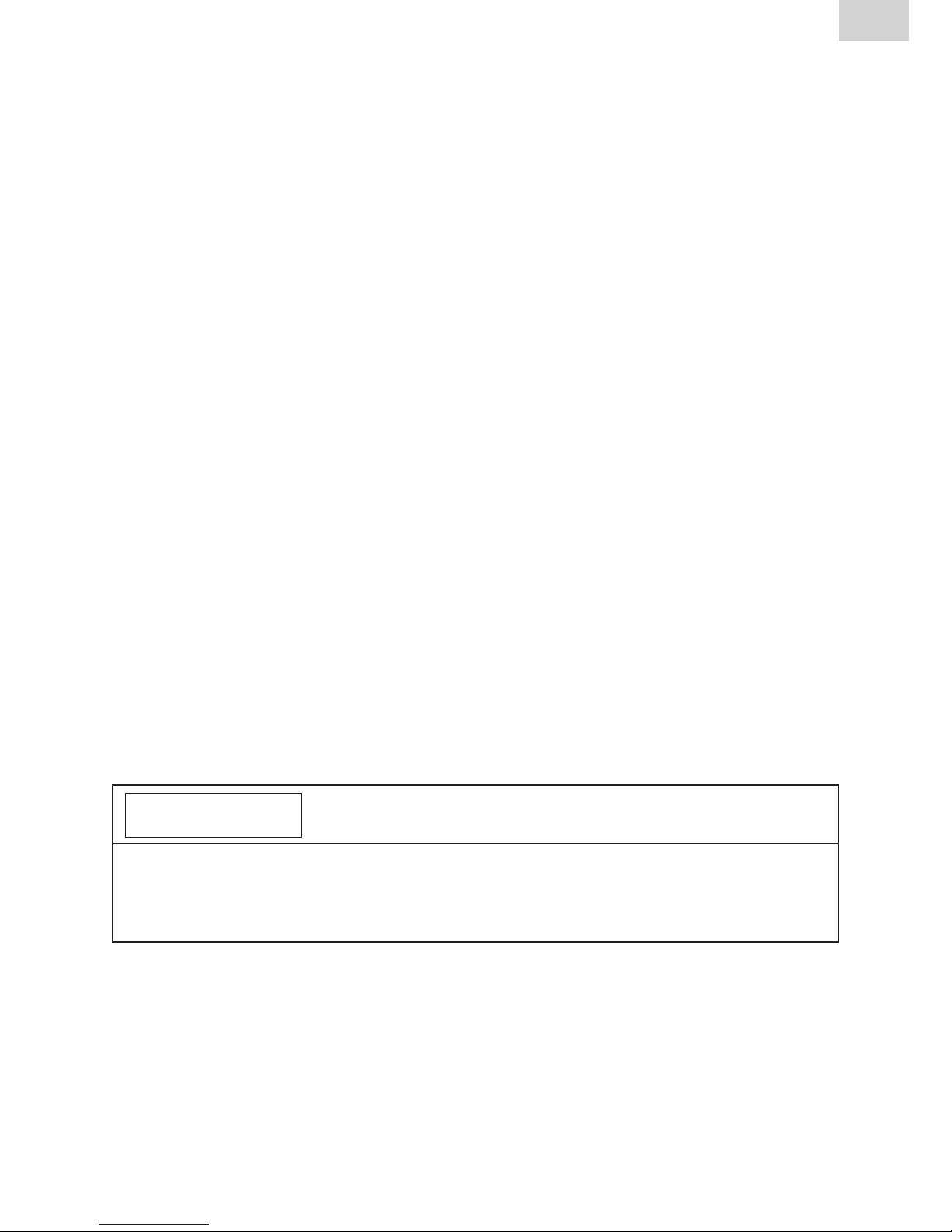
5.1 Function keys explained
1
2 3
4
5
1 Display
The FRIAMAT Basic is fitted with a two-line display.
2 START key
The START key is used to start a fusion procedure, to select sub- or individual menus, and to save settings. This key is also used to confirm messages on the display.
3 STOP key
The STOP key is used to abort a fusion procedure, to close sub- or individual menus, and to cancel an input (without saving).
4 MENU key
The MENU key lies between the direction keys and opens the main menu
with the submenus “Basic Settings”, “Info”, and “Emergency Input”. In the
event of an error, pressing the MENU key displays it in plain text.
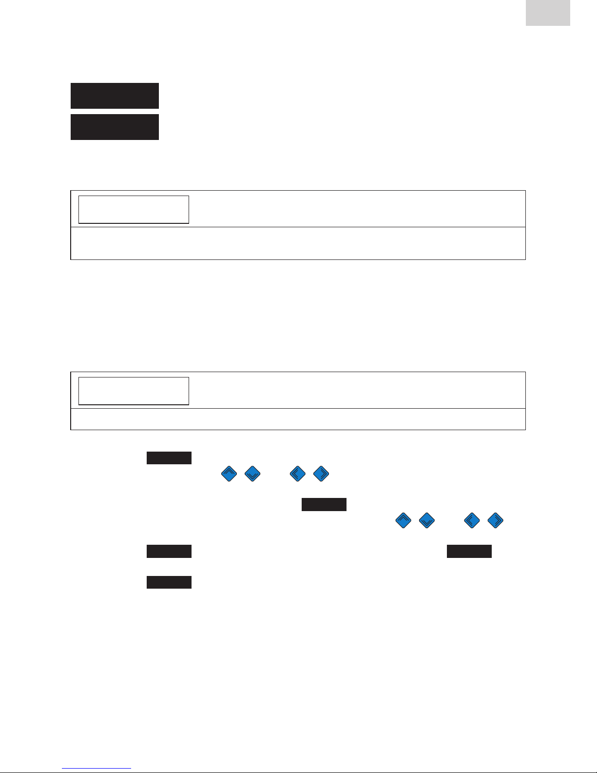
5 Direction keys
The direction keys
(
UP/DOWN) can be used to navigate through
the sub- and individual menus. Where this navigation is possible is shown
by the respective symbols on the display (see Section 4.2). The direction
keys ( LEFT/RIGHT) move the cursor on the display to the left or
right when data are being entered, e.g. emergency input, date. The direction keys ( UP/DOWN) selects the character (letter, number, special
character) at this position.

20
Stand/Update: 01.07.2014
EN
5.2 Display symbols explained
Symbol Description
When this symbol appears in the second display line, the
direction keys ( UP/DOWN) can be used to open
further menus.
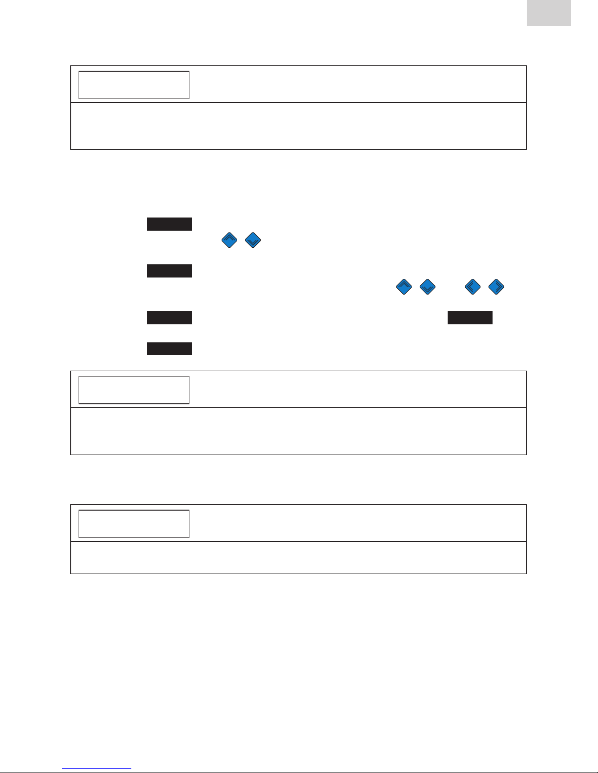
5.3 “Basic Settings” menu
The “Basic Settings” menu lets you edit the device settings.
TIME
DATE
* LANGUAGE *
VOLUME
1. Press the key.
2. Press the direction keys to open the “Basic Settings” submenu.
3. Press the key.
4. Use the direction keys to open the menu for Time, Date, Language,
and Volume.
5. Press the key.
6. Use the direction keys and to make your changes in this
menu.
7. Press the key to save your changes. Press the key to cancel
without saving.
INFORMATION
Two asterisks appear to the left and right of the top line in the “Language”
menu. This lets you find the language settings menu when, for instance, the language was changed by accident.

21
EN
Stand/Update: 01.07.2014
5.4 “Info” menu
The “Info” menu lets you view the device details.
TIME/DATE
VOLTAGE/FREQUENCY
TEMPERATURE
DEVICE NUMBER
SOFTWARE VERSION
MAINTENANCE DATE
1. Press the key.
2. Press the direction keys to open the “Info” submenu.
3. Press the key.
4. Use the direction keys to open the menu for Time/Date,
Voltage/ Frequency, Temperature, Ambient Temperature, Device Number,
Software Version, Maintenance Date.
5. Press the key.
6. Press the or key to close the menu.
5.5 “Emergency Input” menu
The “Emergency Input” menu lets you enter the fusion barcode manually.
1.
Press the key.
2. Press the direction keys to open the “Emergency Input” submenu.
3. Press the key.
4. The display then shows “Code:” followed by 24 digits of which the first
flashes.
INFORMATION
When this is used for the first time, all digits are set to “0”. Afterwards, the last
barcode entered manually is always shown!
5. Use the direction keys and to enter the digits from the barcode on the fusion fitting.
6. Press the key to confirm your input. Press the key to cancel
without saving.
22
Stand/Update: 01.07.2014
EN
6 FRIAMAT Prime
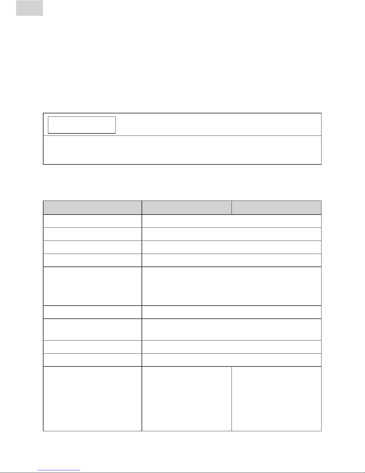
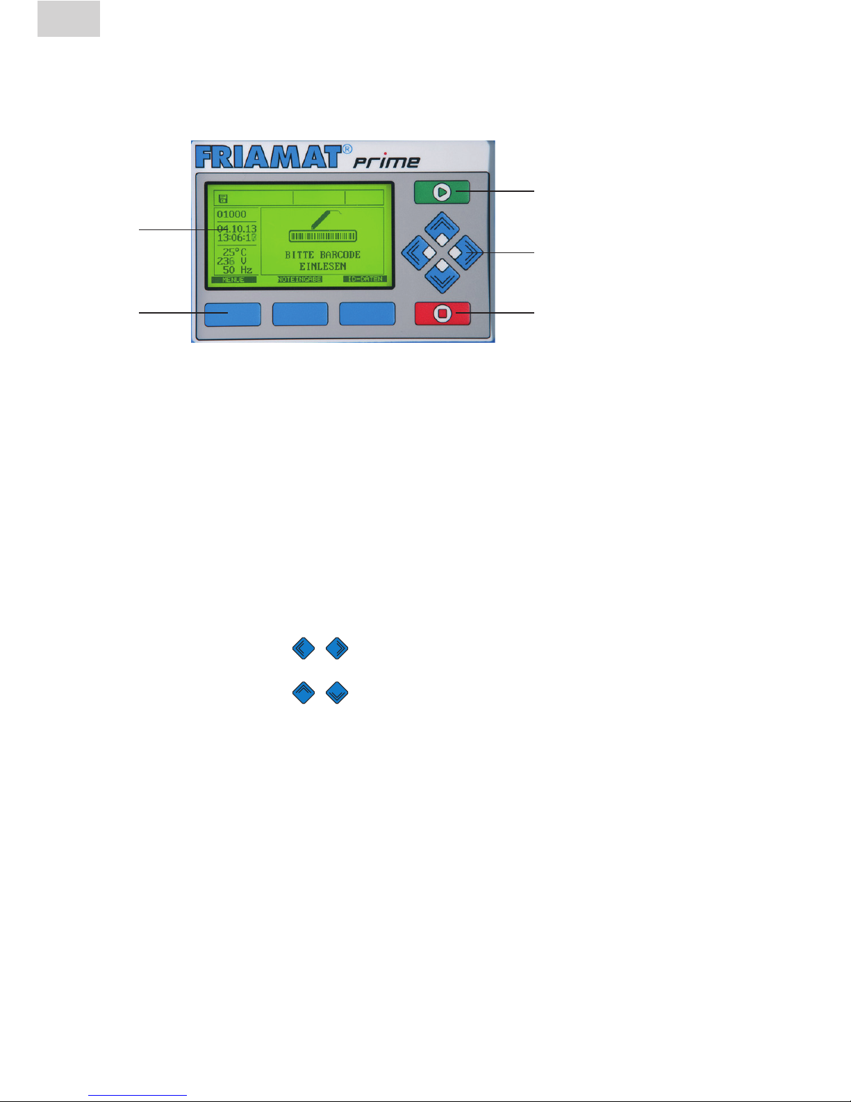
6.1 Function keys explained
1
2
3
4
5
1 Display
The FRIAMAT Basic is fitted with a graphical maxi display.
2 Guide keys
The three blue guide keys let you access the guide key symbols (see Sec-
tions 5.2 and 5.3) that are shown directly at the top of the graphical maxi
display.
3 START key
The START key is used to start a fusion procedure.
4 Direction keys
The direction keys (
LEFT/RIGHT) move the cursor on the display to
the left or right when data are being entered, e.g. emergency input, date.
The direction keys ( UP/DOWN) selects the character (letter, number, special character) at this position.
5 STOP key
The STOP key is used to abort the fusion procedure and to cancel inputs
(without saving). Cancelling inputs with the STOP key always returns you
to the main screen of the graphical maxi display (reset function).

23
EN
Stand/Update: 01.07.2014
6.2 Display layout (main screen)
1
2
3
4
1 Function status symbols
Symbols appear representing the functions that can be activated at this
time (e.g. documentation, traceability mode). See also Section 6.4. Also
shown is the next due maintenance (see also Section 6.13.1.5).
2 View ambient details
Key ambient details are shown (date, time, ambient temperature, voltage,
and frequency).
3 Main window
The main window presents all inputs and details in each of the menus. See
also Section 6.1.
4 Guide key symbols
This presents the functions that are activated at each of the blue guide
keys. The symbols shown vary depending on the menu selected (see also
Section 6.3).

24
Stand: 01.07.2014
6.3 Function key symbols explained
Symbol Description
MENUE
This opens the main menu.
SELECT
This opens a submenu.
OK
This confirms the information shown in the
main window.
SAVE
This saves the entered data.
CANCEL
This cancels an input without saving. Back to the
previous input step.
FORWARD
This takes you to the next input step.
BACK
This takes you back to the previous input step.
ALL
This selects all.
NEW
This lets you enter new values in text fields (e.g. info
text, commission number, etc.)
CHANGE
This lets you change menu settings and/or text inputs
(e.g. the last ten commission numbers)
SHIFT
In edit mode: this switches between delete and insert.
REMOVE
This deletes one or more characters in text inputs.
ADD
This adds one or more characters in text inputs.
DETAILS
This shows the decrypted traceability barcode.
ID-DATA
This assigns data (commission number, operator pass,
serial number, and/or seam number) to the fusion that is
now to be started (see also Section 6.4.3).
25
EN
Stand/Update: 01.07.2014
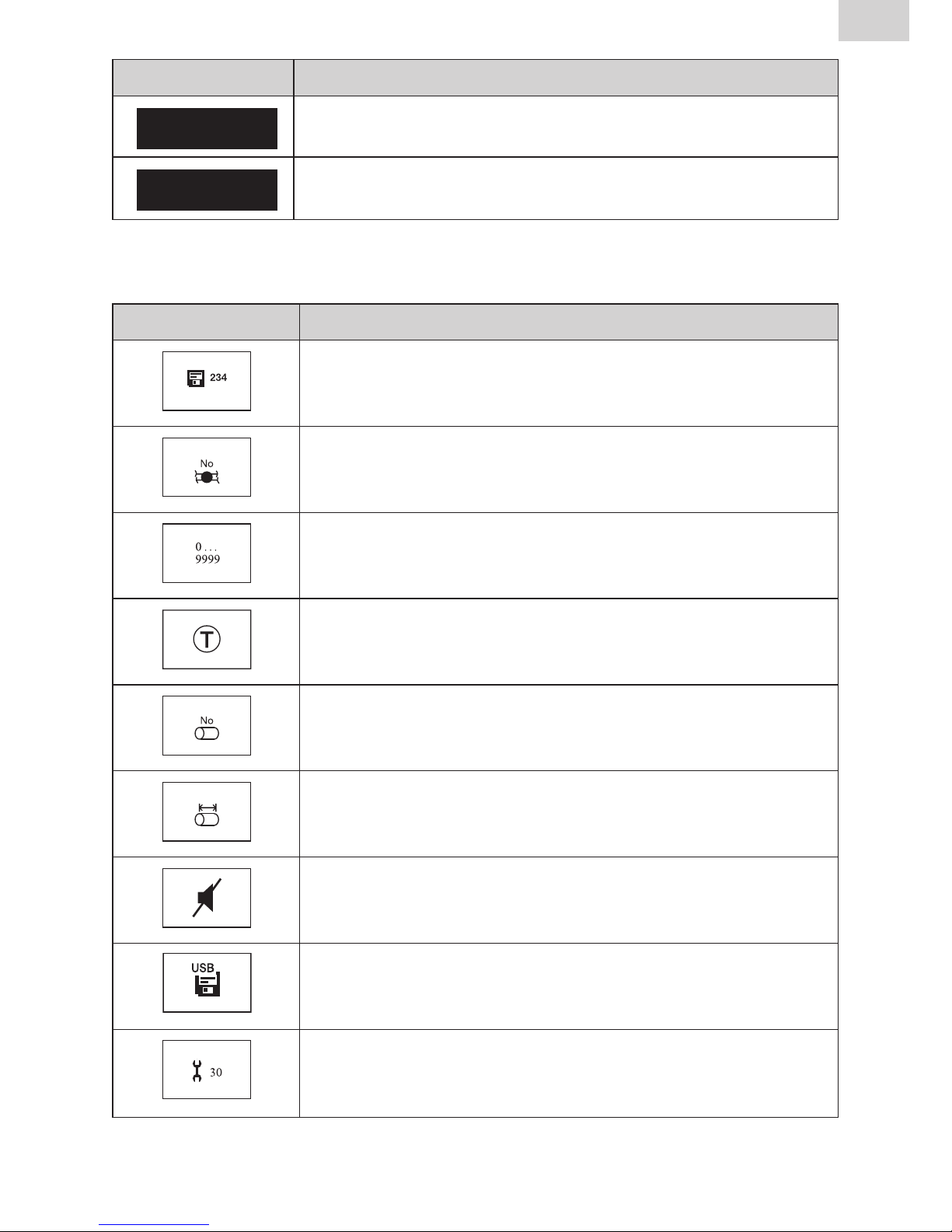
6.4 Function status symbols explained
Symbol Description
Documentation has been activated. The free memory
locations are shown.
Seam numbers can be entered.
The serial numbers are presented in ascending order,
and not according to commission number.
Traceability barcodes can be entered.
Pipe numbers can be entered.
Pipe lengths can be entered.
Acoustic signals have been deactivated.
FRIATEC memory stick has been connected.
Maintenance date: the next due maintenance (in days)
is shown.
Symbol Description
EMERGENCY
INPUT
This lets you enter the barcode manually, e.g. when this
cannot be read in (see also Section 5.10.4).
INFOTEXT
This lets you add additional text information to the
fusion entry (see also Section 6.4.3).

26
Stand/Update: 01.07.2014
EN
6.5 Main window symbols explained
Symbol Description
A ticked box indicates that this menu item or this
function has been activated.
An empty box indicates that this menu item or this
function has not been activated.
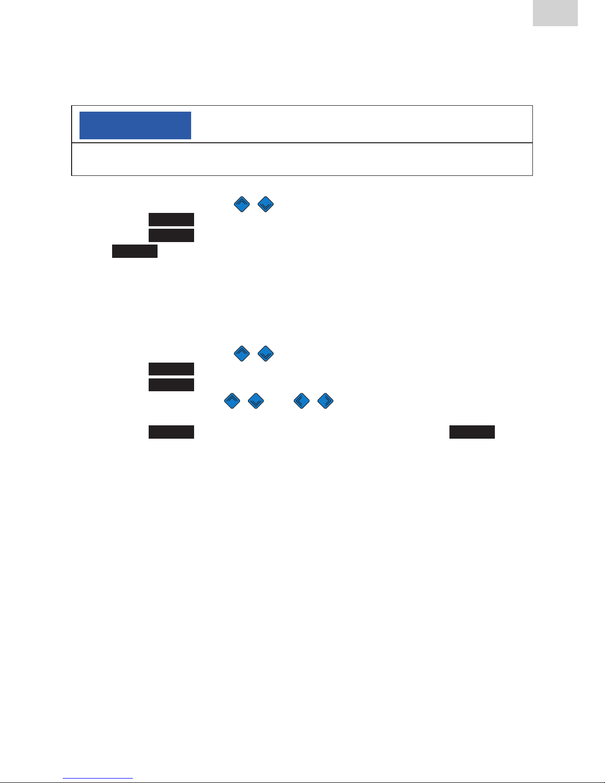
6.6 “Basic Settings” menu
The “Basic Settings” menu lets you edit the device settings.
DOCUMENTATION
TIME
DATE
LANGUAGE
PROTOCOL LANGUAGE
VOLUME
1. Press the
MENU
guide key.
2. Press the direction keys to open the “Basic Settings” submenu.
3. Press the
SELECT
guide key.
4. Use the direction keys to open the menu for Documentation, Time,
Date, Language, Protocol Language, and Volume.
5. Press the
SELECT
guide key.
6. Use the direction keys and or the guide key
CHANGE
to make
your changes in this menu.
7. Press the
SAVE
guide key to save your changes. Press the
CANCEL
guide
key to cancel without saving.

27
EN
Stand/Update: 01.07.2014
6.6.1 Documentation
INFORMATION
The FRIAMAT Prime is delivered with deactivated documentation!
The function Documentation stores the fusion parameters. Each of these can
be assigned to an commission number and/or an operator pass. The documentation can be activated or deactivated in the Documentation submenu.
6.6.2 Time
The “Time” submenu lets you set the current time of day.
6.6.3 Date
The “Date” submenu lets you set the current date.
INFORMATION
The date can be changed only when fusion is performed for the first time,
hence activating the maintenance interval. See also Section 3.10!
6.6.4 Language
The “Language” submenu lets you set the display language.
INFORMATION
Two asterisks appear to the left and right of the top line in the “Language”
menu. This lets you find the language settings menu when the language was
changed by accident!
28
Stand/Update: 01.07.2014
EN
6.6.5 Protocol language
The “Protocol language” submenu lets you set the language for the documentation. The log language can be set independently of the display language.
6.6.6 Volume
The “Volume” submenu lets you set the volume to “high” or “low”.
6.7 “Emergency Input” menu
The “Emergency Input” menu lets you enter the fusion barcode manually.
The digits you enter must be taken from the barcode on the fusion fitting.
INFORMATION
When this is used for the first time, all digits are set to “0”. Afterwards, the last
barcode entered manually is always shown!
1. Press the
EMERGENCY
INPUT
guide key.
2. The display then shows “Code:” followed by 24 digits (with the first flashing) or the digits from the barcode last entered manually.
3. Use the direction keys and to enter the digits from the barcode on the fusion fitting.
4. Press the
SAVE
guide key to save your changes. Press the
CANCEL
guide
key to cancel without saving.
6.8 “Fusion Sequence” menu
INFORMATION
The “Fusion Sequence” menu is first activated and hence shown on the display
when documentation has been activated. All submenus are not activated on
delivery (default)!
The “Fusion Sequence” menu lets you select the information to be assigned
to each fusion procedure.

29
EN
Stand/Update: 01.07.2014
COMMISSION NUMBER
OPERATOR PASS
INFO TEXT
COMMENT 1
COMMENT 2
SUBCONTRACTOR
TRACEABILITY
PIPE NUMBER
PIPE LENGTH
GPS DATA
SEAM NUMBER
SCRAPER TOOL
1. Press the
MENU
guide key.
2. Press the direction keys to open the “Basic Settings” submenu.
3. Press the
SELECT
guide key.
4. Use the direction keys to open the menu for commission number,
operator pass, Info Text, Comment 1, Comment 2, Subcontractor,
Traceability, Pipe Number, Pipe Length, GPS Data, Seam number,
Scraper Tool.
5. Press the
SELECT
guide key.
6. Use the direction keys and or the guide key
CHANGE
to make
your changes in this menu.
7. Press the
SAVE
guide key to save your changes. Press the
CANCEL
guide
key to cancel without saving.
6.8.1 Commission number
The work with commission numbers can be activated or deactivated at the
CHANGE
guide key. When “Commission number” is activated, the commission number “#####################” appears on the display’s main
screen next to “ ➔ CODE” in the top line.
6.8.2 Operator pass
INFORMATION
The “Operator pass” menu is first activated and hence shown on the display
when an operator pass is read in for the first time (and documentation is
activated)!
After an operator pass has been read in for the first time, all fusions performed from this time on will be stored under the code for this operator pass.
The FRIAMAT Prime is reconfigured accordingly when another operator pass
is read in.

30
Stand/Update: 01.07.2014
EN
Reading in an operator pass opens the “ID Data” submenu (see also Section
6.8.1).Youcanusethedirectionkeys to view the settings activated on
the FRIAMAT Prime. Press the guide key
OK
to exit the submenu.
The operator pass can be used to lock the FRIAMAT Prime as protection
against unauthorised use. The display on a locked FRIAMAT Prime shows the
prompt “PLEASE ENTER VALID OPERATOR PASS!”.
Locking the device
1. Again read in the current operator pass.
2. Press the
OK
guide key to confirm the prompt “LOCK DEVICE?”.
Alternatively, you can abort the procedure at the
CANCEL
guide key.
3. The FRIAMAT Prime is also locked automatically when an operator pass
has been read in and the date changes, i.e. the FRIAMAT Prime is locked
on the next day. In both of these cases (manual or automatic locking), the
display shows the prompt “PLEASE ENTER VALID OPERATOR PASS!”.
Unlocking the device
1. Read in an operator pass.
2. The valid operator pass appears on the display and must be confirmed
with the guide key
OK
.
6.8.3 Info Text
The “Info Text” submenu lets you decide whether additional text information
can be entered for a fusion.
6.8.4 Comment 1
The “Comment 1” submenu lets you decide whether additional text information can be entered for a fusion.
6.8.5 Comment 2
The “Comment 2” submenu lets you decide whether additional text information can be entered for a fusion.

31
EN
Stand/Update: 01.07.2014
6.8.6 Subcontractor
The “Subcontractor” submenu lets you decide whether additional text information can be entered for a fusion.
6.8.7 Traceability
The “Traceability” submenu lets you enable the FRIAMAT Prime for reading
in, processing, and storing traceability barcodes. Enabling this menu also
activates the submenus “Pipe Number” and “Pipe Length”.
6.8.8 Pipe Number
The “Pipe Number” submenu lets you decide whether an individual pipe
number can be entered for each of the fusion pipes.
6.8.9 Pipe Length
The “Pipe Length” submenu lets you decide whether the length can be
entered for each of the fusion pipes.
6.8.10 GPS Data
The “GPS Data” submenu lets you decide whether the coordinates/location
of the fitting can be entered for a fusion.
INFORMATION
A corresponding device is needed to determine the GPS data!
6.8.11 Seam number
The “Seam number” submenu lets you decide whether a seam number can
be entered for a fusion.
6.8.12 Scraper tool
The “Scraper Tool” submenu lets you decide whether the data (e.g. device
number) of the scraper tool used to prepare for fusion can be entered for a
fusion. The scraper tool must then bear a corresponding barcode.

32
Stand/Update: 01.07.2014
EN
6.9 “Data” menu
INFORMATION
The “Data” menu is first activated and hence shown on the display when
documentation has been activated and the first data record saved!
The “Data” menu lets you define how the fusion and traceability data are
transferred from the FRIAMAT Prime to the PC or laptop.
TRANSFER
PDF
CSV
DELETE
1. Press the
MENU
guide key.
2. Press the direction keys to open the “Basic Settings” submenu.
3. Press the
SELECT
guide key.
4. Use the direction keys to open the menu for Transfer, PDF, CSV,
Delete.
5. Press the
SELECT
guide key.
6. In this menu, use the corresponding guide keys to initiate the data transfer.
Press the
SELECT
guide key to select the data for transfer. Otherwise, you
can transfer all of the saved data with the
ALL
key.
7. Press the
OK
guide key to confirm the end of data transfer.
6.9.1 Transfer
The “Transfer” submenu lets you read out and transfer data from the
FRIAMATPrime.Youmustusethistotransferdatafromamemorystickinthe
FRIAMAT Prime’s USB port (see also Section 8.1). The data are saved to an
FTD file on the memory stick and can be processed with the FRIATRACE
data base software on a PC or laptop.
NOTE
FRIATEC accepts no warranty claims arising from the use of standard USB
sticks. Use the FRIATEC memory stick!

33
EN
Stand/Update: 01.07.2014
6.9.2 PDF
The “PDF” submenu lets you save data to a PDF file on the FRIATEC memory
stick.YoumustusethistotransferdataasaPDFletothememorystickin
the FRIAMAT Prime’s USB port (see also Section 8.1). The PDF files are written
to a subdirectory on the memory stick. This subdirectory is named as follows
(here an example): F+device number (e.g. FR 14 81 001): F1481001
The file names are made up of the current data and a two digit number incremented from 0. For example, the second printout (02) on 24/01/2014 (130201):
14012402.PDF
The PDF files can then be printed out with the right software (e.g. Acrobat
Reader
©
) on a PC or laptop.
6.9.3 CSV
The “CSV” submenu lets you save data to a CSV file on the FRIATEC memory
stick.YoumustusethistotransferdataasaCSVletothememorystickin
the FRIAMAT Prime’s USB port (see also Section 8.1). The CSV files are written to a subdirectory on the memory stick. This subdirectory is named as follows (here an example): F+device number (e.g. FR 14 81 001): F1481001
The file names are made up of the current data and a two digit number incremented from 0. For example, the second printout (02) on 24/01/2014 (130201):
14012402.CSV
The CSV files can then be read in and printed out with the right software (e.g.
Microsoft
©
Excel) on a PC or laptop.

34
Stand/Update: 01.07.2014
EN
6.9.4 Delete
The “Delete” submenu lets you delete all of the saved data.
NOTE
Deleted data are irretrievably lost!
6.10 “Info” menu
The “Info” menu presents some key details of the FRIAMAT Prime: device
number,softwareversion,nextmaintenancedate.Youwillneedthesedetails
when contacting the FRIATEC service station, e.g. when problems occur.
1. Press the
MENU
guide key.
2. Press the direction keys to open the “Info” submenu.
3. Press the
SELECT
guide key.
4. Press the
OK
guide key to close the menu.
6.11 “Formatting” menu
The “Formatting” menu can be used to format USB sticks to FAT 12 or
FAT 16.
The FRIATEC memory stick must be used for transferring data from the
FRIAMAT Prime. Please bear in mind when using a standard USB stick that
this must be formatted to FAT 12 or FAT 16. A FAT 32 or partitioned USB stick
(with master boot record) will cause the error message “ERROR 91” to appear
on the FRIAMAT Prime. Also, the capacity of the USB stick used must not
exceed 2 GB.
NOTE
Formatting deletes all data!
Bear in mind that formatting deletes all data on the memory stick.

35
EN
Stand/Update: 01.07.2014
1. Press the
MENU
guide key.
2. Press the direction keys to open the “Format” submenu.
3. Press the
SELECT
guide key.
4. Selectingthemenuitem“MEMORYSTICK”openstheprompt
“AREYOUSURE?”.
5. Press the
OK
guide key.
6. Press the
OK
guide key to acknowledge the message
“MEMORYSTICKNOWFORMATTED”.
NOTE
Use the FRIATEC memory stick!
FRIATEC accepts no warranty claims arising from the use of standard USB sticks.
6.12 Fusion options
6.12.1 ID Data
INFORMATION
The “ID Data” option is first activated and hence shown on the display when
documentation has been activated!
“ID Data” are data that can be assigned directly to the fusion that is now to
be started: commission number, operator pass, serial number, and seam
number. These additional details are described in the following.
INFORMATION
Commission numbers and seam numbers can be entered only when the documentation and the functions “Commission number” (see Section 6.4.1) or
“Seam Number” (see Section 6.4.11) have been activated!
6.12.1.1 Commission number
1. Press the
ID-DATEN
guide key.
2. Use the direction keys to select “Commission number”.
3. When entering an commission number for the first time, press the
CHANGE
guide key.
4. The first digit starts to flash. Press the direction keys and to
enter the commission number.
5. Press the
SAVE
guide key to save your changes. Press the
CANCEL
guide
key to cancel without saving.
36
Stand/Update: 01.07.2014
EN
When one or more commission numbers have already been entered, you can
choose from “EDIT”, “NEW”, and “SELECT”.
CHANGE
= This lets you edit the commission number entered last.
NEW
= This lets you enter a new commission number.
SELECT
= This lets you select an commission number from the twenty
commission numbers entered last.
6.12.1.2 Operator pass
Pressing the guide key
ID DATA
displays whether and which welder has
been registered. If no operator pass has been activated, the window remains
unchanged.
The welder cannot be edited manually (via key presses). To register a new
welder, you must read in a new operator pass (see Section 6.4.2).
6.12.1.3 Serial number
Pressing the guide key
ID DATA
displays the serial number of the executed
fusions. This number is assigned automatically by the device and cannot be
changed. Normally the serial number is assigned to the activated commission
number.
INFORMATION
The Supervisor function (see Section 6.9) lets you specify other assignments to
the commission number (see Section 6.9.2.9)!
6.12.1.4 Seam number
The “Seam number” menu assigns a user defined number (seam number) to
the fusion.
1. Press the
ID DATA
guide key.
2. Use the direction keys to select “Seam number”.
3. To enter a seam number, press the
CHANGE
guide key.
4. The first digit starts to flash. Press the direction keys and to
enter the seam number.
5. Press the
SAVE
guide key to save your changes. Press the guide key to
cancel without saving.
6. Press the
OK
guide key to close the menu.
37
EN
Stand/Update: 01.07.2014
When a seam number has already been assigned, you can choose between
“CHANGE” and “NEW”.
CHANGE
= This lets you edit the seam number entered last.
NEW
= This lets you enter a new seam number.
6.12.1.5 GPS 1 – 3
INFORMATION
Data can be entered under GPS 1, GPS 2, and GPS 3 only when this has been
activated (see Section 6.4.10)!
The coordinates/location of the fusion (GPS 1, GPS 2, GPS 3) can be entered
in the menu “GPS 1 – 3”. The GPS data are made up of three input fields:
GPS 1 for the geographical longitude, GPS 2 for the geographical latitude, and
GPS 3 for the altitude above sea level. GPS 1 can take a string of thirteen user
definable alphanumerics, GPS 2 twelve, and GPS 3 ten.
INFORMATION
A corresponding device is needed to determine the GPS data!
1. Press the
ID DATA
guide key.
2. Use the direction keys and to select “GPS 1”, “GPS 2”, and
“GPS 3”.
3. To enter GPS coordinates, press the
CHANGE
guide key.
4. The first digit starts to flash. Press the direction keys and to
enter the GPS coordinates.
5. Press the
SAVE
guide key to save your changes. Press the
CANCEL
guide key to cancel without saving.
6. Press the
OK
guide key to close the menu.

38
Stand/Update: 01.07.2014
EN
When GPS coordinates have already been entered, you can choose between
“EDIT” and “NEW”.
CHANGE
= This lets you edit the GPS coordinates entered last.
NEW
= This lets you enter new GPS coordinates.
6.12.2 Traceability Barcodes / Pipe Number / Pipe Length
INFORMATION
Traceability data can be entered only when documentation and the function
“Traceability” and/or “Pipe Number” and/or “Pipe Length” has been activated
(see Section 5.6.7).
Traceability Barcodes is activated when the fusion barcode on the fusion fitting
is read in. The main window prompts you to enter the traceability barcode on
the fitting. When this is to be read in (visualised by a ticked box), you are
prompted to enter the traceability barcode on Component 1. When the pipe
number and/or pipe length is to be entered, this is also displayed for input.
Now you are prompted to enter the traceability barcode on Component 2. The
pipe number and/or pipe length is entered analogously to the above.
Press the function key
OK
to acknowledge the prompt
“Pipe Processed?” when the fusion pipe has been processed properly.
Press the key to start fusion.
INFORMATION
The traceability data are input automatically, i.e. the display presents the
entered data in succession until fusion can be started.
You can use the guide keys
FORWARD
and
BACK
to switch at any time between
the prompts “Fitting”, “Component 1”, “Component 2”, “Pipe Processed?”, and
“Start”. Use the direction keys to switch between prompt.
39
EN
Stand/Update: 01.07.2014
6.12.3 Info Text, Comment 1, Comment 2, Subcontractor
INFORMATION
Data can be entered under INFO TEXT, COMMENT 1, COMMENT 2, and/or
SUBCONTRACTOR only when these have been activated (see Section 6.4.3
to 6.4.6)!
After the fusion barcode has been read in, “INFO TEXT” appears on the display.
1. Press the
INFOTEXT
guide key.
2. Use the direction keys to select “INFO TEXT”, “COMMENT 1”,
“COMMENT 2”, and/or “SUBCONTRACTOR”.
3. Press the
INPUT
guide key.
4. The first digit starts to flash. Press the direction keys and to
enter the data.
5. Press the
SAVE
guide key to save your changes. Press the
CANCEL
guide key to cancel without saving.
6. Press the
OK
guide key to close the menu.
INFORMATION
The additional text must be entered for each fusion if it is to appear in the log.
No additional text is added to the fusion data when the START key is pressed
directly after the fitting barcode has been read in.
6.12.4 Scraper tool
INFORMATION
Data can be entered under SCRAPER TOOL only when this has been activated
(see Section 6.4.12).
When the data are being entered to start fusion, the prompt “PIPE PROCESSED?” is followed by the prompt “SCRAPER TOOL: PLEASE READ IN
BARCODE”. When the scraper tool bears a barcode, this can be read in. The
data are then assigned to the fusion in the log.

40
Stand/Update: 01.07.2014
EN
6.13 SUPERVISOR
The SUPERVISOR menu lets you configure the FRIAMAT Prime properties
and functions. Device functions can be enabled or locked specifically for the
user, and the sequence of operations specified for the building site. A special
pass (SUPERVISOR pass) is needed to configure the Supervisor menu.
INFORMATION
The settings and menus locked under SUPERVISOR are no longer displayed
for the user on the building site (e.g. when documentation has been activated,
yet locked against user access, the “Documentation” menu no longer appears
on the display)!
The “SUPERVISOR” menu first opens when the barcode is read in on the
SUPERVISOR pass. A four digit PIN must be entered here. The default PIN is
“0000”. The PIN can be changed at any time under the “Supervisor” menu
(see Section 6.9.4).
BASIC SETTINGS
FUSION SEQUENCE
FACTORYSETTINGS
PIN
DISPLAY(RESISTANCE)
1. Read in the SUPERVISOR pass.
2. Enter the four digit PIN. Press the
SAVE
guide key to confirm the dis-
played PIN. Press the
CHANGE
guide key to change the PIN.
3. Press the
OK
guide key to open the Supervisor menu.

41
EN
Stand/Update: 01.07.2014
6.13.1 Basic Settings
The “Basic Settings” Supervisor menu lets you edit the device settings.
DOCUMENTATION
TIME
DATE
DATA PROTECTION
MAINTENANCE DATE
MODE
LANGUAGE
EMERGENCYINPUT
ENERGYDISPLAY
VOLUME
1. Press the direction keys to open the “Basic Settings” submenu.
2. Press the
SELECT
guide key.
3. Use the direction keys to open the menu for Documentation, Time,
Date, Data Protection, Maintenance Date, Mode, Language, Emergency
Input, Energy Display, and Volume.
4. Press the
SELECT
guide key.
5. Use the direction keys and or the guide key
CHANGE
to make
your changes in this menu.
6. Press the
SAVE
guide key to save your changes. Press the
CANCEL
guide
key to cancel without saving.
6.13.1.1 Documentation
The documentation can be activated or deactivated in the “DOCUMENTATION”
submenu. This setting can be locked against user access.
6.13.1.2 Time
The “TIME” submenu can be used to protect the time against user changes.
6.13.1.3 Date
The “DATE” submenu can be used to protect the date against user changes.

42
Stand/Update: 01.07.2014
EN
6.13.1.4 Data Protection
The “DATA PROTECTION” submenu can be used to protect data against user
deletion. Or it can let the user delete the data after they have been printed out
or transferred out of the device.
6.13.1.5 Maintenance Date
In the “MAINTENANCE DATA” submenu, you can decide whether the warn-
ing “Maintenance date exceeded” is to be deactivated or the device no longer
executes fusions when this date is exceeded. In the latter case, you can set a
period from 0 to max 99 days during which the device continues to operate
after the maintenance date has been exceeded. This setting is displayed to the
user after the maintenance date has been exceeded (a spanner with the number of days the device will continue to operate).
6.13.1.6 Mode
The “MODE” submenu can be used to set various date and time formats as
well as temperature units.
6.13.1.7 Language
The “LANGUAGE” submenu fixes the language, i.e. the user cannot set another language.
6.13.1.8 Emergency Input
The “EMERGENCY INPUT” submenu can disable the option of entering the
barcode digits manually.
6.13.1.9 Energy Display
In the “ENERGY DISPLAY” submenu, you can decide whether the energy
consumed by the fusion procedure is to be displayed or not.
6.13.1.10 Volume
The “VOLUME” submenu can be used to set the volume of the acoustic signal
(ON/OFF, HIGH/LOW). Also, the selected settings can be locked against user
access.

43
EN
Stand/Update: 01.07.2014
6.13.2 Fusion Sequence
In the “Fusion Sequence” Supervisor menu, you can define the data that can
be assigned to the fusion that is now to be started.
TRACEABILITY
COMMISSION NUMBER NUMBER
INFO TEXT
SEAM NUMBER
SERIAL NUMBER
OPERATORS PASS
PIPEPREPARED?DISPLAY
1. Press the direction keys to open the “Fusion Sequence” submenu.
2. Press the
SELECT
guide key.
3. Use the direction keys to open the menu for Traceability, Commission number, Info Text, Seam number, Serial Number, Operator pass, and
Pipe Processed? Display.
4. Press the
SELECT
guide key.
5. Use the direction keys and or the guide key
CHANGE
to make
your changes in this menu.
6. Press the
SAVE
guide key to save your changes. Press the
CANCEL
guide
key to cancel without saving.
6.13.2.1 Traceability
The option of entering traceability barcodes, pipe numbers, and pipe lengths
can be activated or deactivated in the “TRACEABILITY” submenu. Also, the
selected settings can be locked against user access.
6.13.2.2 Info Text
Text entries can be activated or deactivated in the “INFO TEXT” submenu.
Also, the selected settings can be locked against user access.
6.13.2.3 Comment 1
Text entries can be activated or deactivated in the “COMMENT 1” submenu.
Also, the selected settings can be locked against user access.
6.13.2.4 Comment 2
Text entries can be activated or deactivated in the “COMMENT 2” submenu.
Also, the selected settings can be locked against user access.

44
Stand/Update: 01.07.2014
EN
6.13.2.5 Subcontractor
Text entries can be activated or deactivated in the “SUBCONTRACTOR” submenu. Also, the selected settings can be locked against user access.
6.13.2.6 GPS Data
Coordinate entries can be activated or deactivated in the “GPS DATA” sub-
menu. Also, the selected settings can be locked against user access.
6.13.2.7 Seam number
Entering seam numbers can be activated or deactivated in the
“SEAM NUMBER” submenu. Also, the selected settings can be locked
against user access.
6.13.2.8 Serial number
In the “SERIAL NUMBER” submenu, you can decide whether the serial number (assigned by the device) is assigned to the commission number (within the
commission number, beginning with “1”) or independently of it, i.e. consecutively.
6.13.2.9 Commission number
Work with commission numbers can be activated or deactivated in the
“ Commission number” submenu. In addition, you can specify whether the
commission number is to be entered every time the device is switched ON
and/or before each fusion. Also, the selected settings can be locked against
user access.
6.13.2.10 Operators pass
Work with an operator pass can be activated or deactivated in the
“ OPERATOR PASS” submenu. In addition, when an operator pass has been
activated, you can deactivate the default setting that the operator pass must
be read in again on a change of date (i.e., in activated mode, the device is first
locked the next day until an operator pass has been read in).
In addition, you can also specify whether the operator pass is to be entered
every time the device is switched ON and/or before each fusion. Also, the selected settings can be locked against user access.
6.13.2.11 Pipe Prepared? Display
In the “PIPE PREPARED? DISPLAY”, you can activate or deactivate the
warning shown before fusion starts.
45
EN
Stand/Update: 01.07.2014
6.13.3 Factory Settings
The “Factory Settings” Supervisor menu lets you reset all user settings to
their default values (state on delivery).
NOTE
All settings and text entries are irretrievably lost when reset to their default
values!
1. Press the direction keys to open the “Factory Settings” submenu.
2. Press the
OK
guide key.
3. Press the
SELECT
guide key to reset all settings to their default values, or
the
CANCEL
guide key to abort.
6.13.4 PIN
In the “PIN” supervisor menu, you can change the default value “0000” for
accessing the “SUPERVISOR” menu.
1. Press the direction keys
to open the “PIN” submenu.
2. Press the
SELECT
guide key.
3. Press the
CHANGE
guide key.
4. Use the direction keys and to enter the new four digit PIN.
The old PIN is shown above.
5. Press the
SAVE
guide key to save your changes. Press the
CANCEL
guide
key to cancel without saving.
46
Stand/Update: 01.07.2014
EN
INFORMATION
The entered PIN should be noted down and kept in a safe place together with
the SUPERVISOR pass. In the event of a lost PIN, contact our service hotline
+49 (0)621 486-1533!
6.13.5 Display (Resistance)
In the “DISPLAY (RESISTANCE)” Supervisor menu, you can decide whether
the actual measured resistance is to be displayed before the start of fusion on
the fitting.
1. Press the direction keys
to open the “Display (Resistance)” sub-
menu.
2. Press the
SELECT
guide key.
3. Use the direction key
CHANGE
to make your changes in this menu.
4. Press the
SAVE
guide key to save your changes. Press the
CANCEL
guide
key to cancel without saving.
7 Warranty/maintenance/disposal
7.1 Warranty
FRIAMAT fusion units come with a 24 month warranty.
7.2 Maintenance and care
In accordance with DVS 2208 Part 1 and BGV A3 (“Electrical systems and
equipment”), nonstationary electrical equipment must be subjected to repeat
tests at least once a year. This maintenance can be performed at FRIATEC
or one of its authorised service stations (see Section 8.2).
47
EN
Stand/Update: 01.07.2014
Also all connection adapters must be submitted for tests on the maintenance
dates.
What? When? Who?
Clean the wand, and Daily Operator
check for damage.
Check function. Before every use Operator
Check and, if necessary, Before every use Operator
clean contacts.
Factorymaintenance Yearly FRIATECAGorauthorised
service stations
7.3 Disposal
The European Directive 2002/96/EC on waste electrical and electronic equipment (WEEE) regulates the disposal of used electrical
and electronic products. The WEEE Directive 2005 was implemented
as the ElektroG on the German disposal sector. Under these laws,
waste electrical and electronic equipment must be introduced to a proper
disposal or recycling process. FRIAMAT fusion units fall under this European
Directive and can be submitted for disposal to FRIATEC AG or one of its authorised service stations.
Further regulations, standards, and directives applying in the country of use
must be observed.

48
Stand/Update: 01.07.2014
EN
8 Error messages / warnings / info
Irregularities during fusion cause error messages or warnings to appear on the
display of the FRIAMAT fusion unit.
INFORMATION
On the FRIAMAT Basic, press the Menu key to view the displayed error
message in plain text!
INFORMATION
Should the FRIAMAT fusion unit output an error message or warning that is
not listed in the following and that cannot be explained or remedied despite
the plaintext description, contact our service hotline +49 (0)621 486-1533!
Error messages
No. Displayed text Meaning/causes Remedy
02 Temperature Ambienttemperatureoutside Youmayhavetotent
out of range of permitted range over or shield the
fusion area.
03 Resistance outside Fitting’s electrical resistance Check that contacts sit
of tolerance outside of tolerance. firmly and are clean. If
necessary, clean contacts and replace the
fitting.
04 Fitting’s wire turn Short circuit in the fitting’s Replace fitting, and
short circuited wire turn. send it in for analysis.
05 Fitting’s wire turn Current flow interrupted Check the connection
interrupted between the fusion
plug and the fitting. If
OK, replace fitting, and
send it in for analysis.
06 Voltage outside Deviation in fusion voltage Notify authorised
of tolerance too high. service station.

49
EN
Stand/Update: 01.07.2014
No. Displayed text Meaning/causes Remedy
08 Operating voltage Operating voltage outside of Extension too long,
out of range permitted range during fusion. or cross section too
small. Check voltage
and connection conditions on the generator.
09 Frequency out of Frequency outside of per- Check frequency of
range mitted range during fusion. generator voltage.
10 Fusion stop Fusion stopped at STOP key. –
13 Operating voltage Supply voltage interrupted Check connection
failure (e.g. power failure during conditions.
fusion) or too low.
14 Power too low Fitting’s power input is too low. Contact the FRIATEC
The FRIAMAT cannot provide service hotline:
such a low power. +49 (0)621 486-1533
15 Power exceeded The fitting’s power input Contact the FRIATEC
exceeds the capacity of the service hotline:
FRIAMAT. +49 (0)621 486-1533
23 Generator error Generator possibly not Contact the FRIATEC
suitable for fusion. service hotline:
+49 (0)621 486-1533
xy* System error Contact the FRIATEC
service hotline:
+49 (0)621 486-1533
*: Error messages whose numbers do not appear in the above table.

50
Stand/Update: 01.07.2014
EN
Warnings/info
Displayed text Tip/remedy
Attention! Double fusion! If you intend double fusion on a fitting, you
must disconnect the fusion unit’s pins from
the fitting after the first fusion, and let it cool
down (see the processing instructions issued by the fitting manufacturer).
Please read in the fusion barcode first. Only FRIAMAT Prime: This appears when
the fitting’s traceability barcode was read in
first by accident.
Please read in a valid traceability Only FRIAMAT Prime: This appears when
barcode. the fitting’s fusion barcode was read in first
by accident.
Please read in a valid operator pass. Only FRIAMAT Prime: This appears when a
operator pass is to be read in (e.g. device
locked) and/or a different (incorrect) barcode was read in.
Please read in a valid commission Only FRIAMAT Prime: This appears when
number. an commission number is to be read in
(e.g. device configured to read before every
fusion) and/or an incorrect value was entered or a different (incorrect) barcode was
read in.
Defect/incorrect barcode Use a new barcode on an identical fitting, or
correct the entered code manually.
Device blocked Only FRIAMAT Prime: When maintenance
date exceeded (see Section 6.13.1.5).
Let the device cool down. Protective function that prevents the device
from overheating. Switch OFF the device,
and let it cool down until the warning no
longer appears after reactivation.
Fusion stop Fusion stopped at STOP key.
End of fusion Fusion finished.
Voltage …V; Only FRIAMAT Basic: Adjust generator,
frequency …Hz and acknowledge at STOP key.
Memory empty Only FRIAMAT Prime: Printout not possible
from empty memory.

51
EN
Stand/Update: 01.07.2014
Displayed text Tip/remedy
Memory full Only FRIAMAT Prime: Print out log.
Maintenance date exceeded Notify authorised service station.
Have the device serviced.
9 Annex
9.1 Recommended accessories (options)
Article name Order no. Description
Memory stick 624023 For saving and transferring fusion data and
writing the print log to a PDF or CSV file (only
FRIAMAT Prime).
SUPERVISOR pass 623101 For custom configurations of menu functions
(only FRIAMAT Prime).
FRIATRACE IV 613280 For the electronic processing of fusion data
(only FRIAMAT Prime).
Operator pass 623101 For identifying the welder and protecting
FRIAMAT fusion units from unauthorised
access. The details entered on the operator
pass (welder’s name and number) are transferred to the fusion log (only FRIAMAT Prime).
9.2 Authorised service stations
Please contact the FRIATEC AG service hotline +49 (0)621 486-1533 for
service stations worldwide.
9.3 Updates to these operating instructions
The technical information contained in these operating instructions is examined regularly for currency. The date of the last revision is specified on every
page.
The latest operating instructions can be viewed on the internet at
www.friatools.de. The download section can be accessed via the navigation
bar. This provides our updated operating instructions in the form of PDF
documents. We shall also be pleased to send you these.

52
Stand: 01.07.2014
FRIATEC Aktiengesellschaft
Division Technical Plastics
P.O.B. 71 02 61 · D-68222 Mannheim
Telefon +49 621 486-1533
Telefax +49 621 486-2030
info-friatools@friatec.de
www.friatools.com
2481/1 · Update: 01.07.2014
 Loading...