

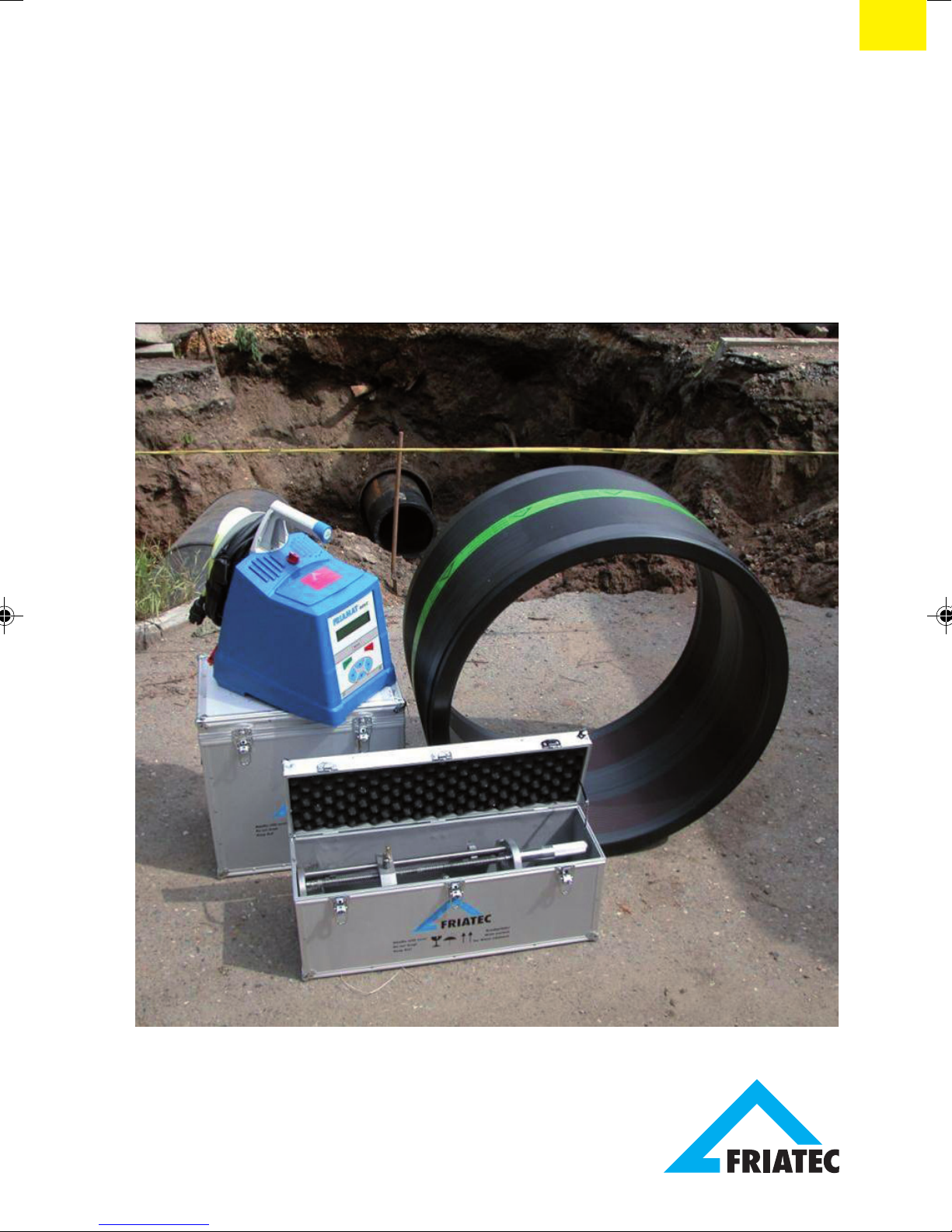
FRIALEN
®
-Large Pipe Technique
for laying large pipes
and relining pipe networks
Fitting Instructions
®
FRIALEN
Large Pipe Technique
Contents Page
FRIALEN® Safety Fittings:
1. Safety 3
2. Areas of Application 3
3. Standard publications and specifications for use 4
4. Couplers from d 250 mm 6
5. Saddle parts - Top Loading 16
6. Pipeline relining 26
7. Update of these assembly instructions 30
For further information on the processing of FRIALEN® Safety Fittings,
please contact:
FRIATEC Aktiengesellschaft
Technical Plastics Division
P.O.B. 710261 · D-68222 Mannheim
Phone +49 621 486-1486
Fax +49 621 479196
Internet: www.frialen.com
Email: info-frialen@friatec.de
Hotline +49 621 486-1486
2
1. Safety
1.1 Safety advice and tips
The following warning symbols are used in these assembly instructions:
DANGER!
Describes impending danger!
Non-observance of this warning may lead to serious damages to health and
objects.
WARNING!
Describes a dangerous situation!
Non-observance of this warning may cause minor injuries or damage to
objects.
IMPORTANT!
Describes advice and other useful information!
2. Areas of Application
FRIALEN® Safety Fittings are used for weld joints at pressure pipes made
of polyethylene in the dimensions SDR 17.6 to SDR 11 for use in gas and
water supply, pressure drainage, industry and landfill construction.
For processing of pipes SDR > 17.6, please call us.
When operating with other media than water and natural gas, please contact
our application engineering department.
IMPORTANT!
The information and processing instructions mentioned on the fitting or
enclosed shall apply predominantly.
3
3. Standard publications and specifications for use
For detailed and up-to-date information on FRIALEN® Safety Fittings, please
see the technical datasheets available on the Internet (www.frialen.com).
Please observe the guidelines of the DVGW standard publications, and of the
DVS, BGR 500 (VBG 50), EN 1555, EN 12201, EN 13244, UVV and
respectively national regulations.
DANGER!
The described sequence of the processes is absolutely to be adhered to.
FRIALEN® Safety Fittings can be used with pipes made of PE 100,
PE 80, PE 63, PE 50 according to DIN 8074/75, EN 1555-2, EN 12201-2,
EN 13244-2, ISO 4437 and ISO 4427.
For PE pipes, a fusion flow rate MFR 190/5 in the range of 0.2 – 1.7g/10 min.
applies.
We recommend using pipes with a limited dimension tolerance range,
tolerance class B.
FRIALEN® Safety Fittings consist of PE 100 and meet the requirements
according to DIN 16963-5, -7, EN 1555-3, EN 12201-3, EN 13244-3,
ISO 8085-3 as well as the DVGW test bases. FRIALEN® Safety Fittings can
be fused with FRIAMAT® Electrofusion Units at ambient temperatures
between - 10 °C and + 45 °C. Fittings from d 710 between 0 °C and + 45 °C.
For material transition joints, the material- or system-specific standards and
installation guidelines apply in addition.
WARNING!
Fusion with other pipe materials such as e.g. PP, PVC etc. is not
possible.
WARNING!
Pipes and moulded components should have settled to a balanced
temperature level between - 10 °C and + 45 °C (Couplers UB d 710 between
0 °C and + 45 °C) when being processed.
4
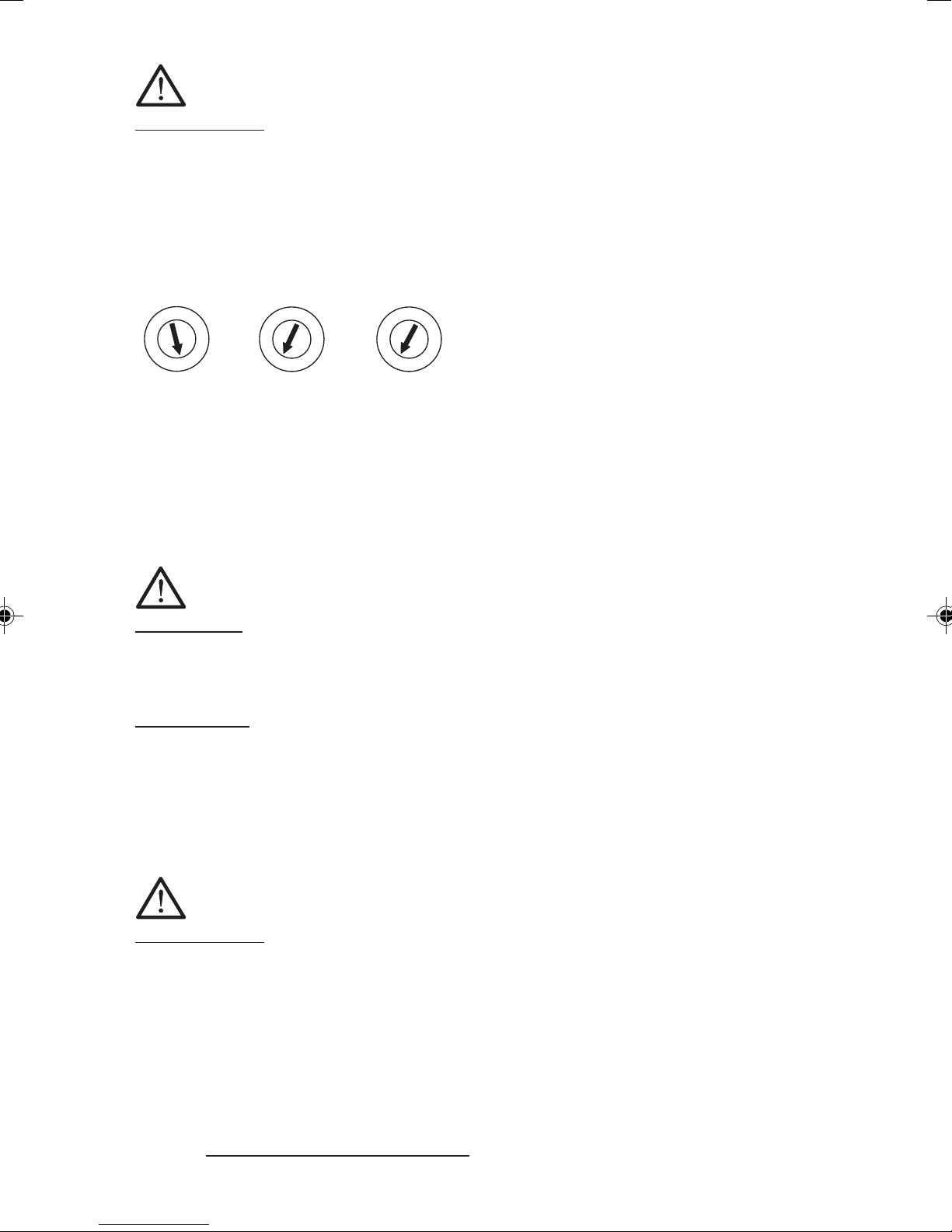
IMPORTANT!
FRIALEN® Safety Fittings are identified by a batch marking.
This reads from left to right:
• Production week (KW) (stamp 1+2)
• Production year (stamp 2)
• Material identification letter (stamp 3)
Example:
0
5
4
0
0
3
0
0
1
2
0
9
8
1
0
7
0
6
1
2
5
3
4
K
J
L
I
M
H
A
G
B
F
C
E
D
KW 14/01/E
The FRIALEN® Safety Fittings can be stored and processed for a long time,
provided the general storage specifications are adhered to. When properly
stored (in closed rooms or containers (boxes)) and/or not exposed to UV
radiation as well as effects of weather (humidity etc.), a storage and
processing period of more than 4 years can be assumed.
WARNING!
Improperly stored component parts may not be processed because
this may result in leaking fusion joints.
Traceability
An automatic component traceability is possible when using e.g. traceabilitycapable FRIAMAT® Electrofusion Units with a special barcode (see Figure 9)
which contains the specific data of the fitting, e.g. manufacturer, dimension,
material, batch. These data on component traceability can be electronically
archived together with the fusion process data.
IMPORTANT!
Manual electrofusion units (without barcode reader), e.g. FWS 225, are
no longer state-of-the art. Processing of FRIALEN® Safety Fittings with
these units is thus no longer possible.
3.1 Pressure load-bearing capability
The pressure load-bearing capability of FRIALEN® Safety Fittings made of
PE 100 is expressed in SDR stages.
SDR =
pipe outer diameter d
pipe wall thickness s
5
The design factor C (calculation coefficient for PE components) depends on
the area of application and the specifications (min. 1.25).
Fitting material: PE 100 Water Gas
(FRIALEN® standard)
SDR Stage maximum operating pressure maximum operating pressure
in bar for new: C = 1.25 in bar for new: C = 2
17 10 5
11 16 10
7.4 25 -
The parts are identified and usable with regard to their load-bearing
capability according to the above table.
DANGER !
Fusion with escaping media is not permissible.
4. Couplers from d 250 mm
4.1 Cutting to length of pipes
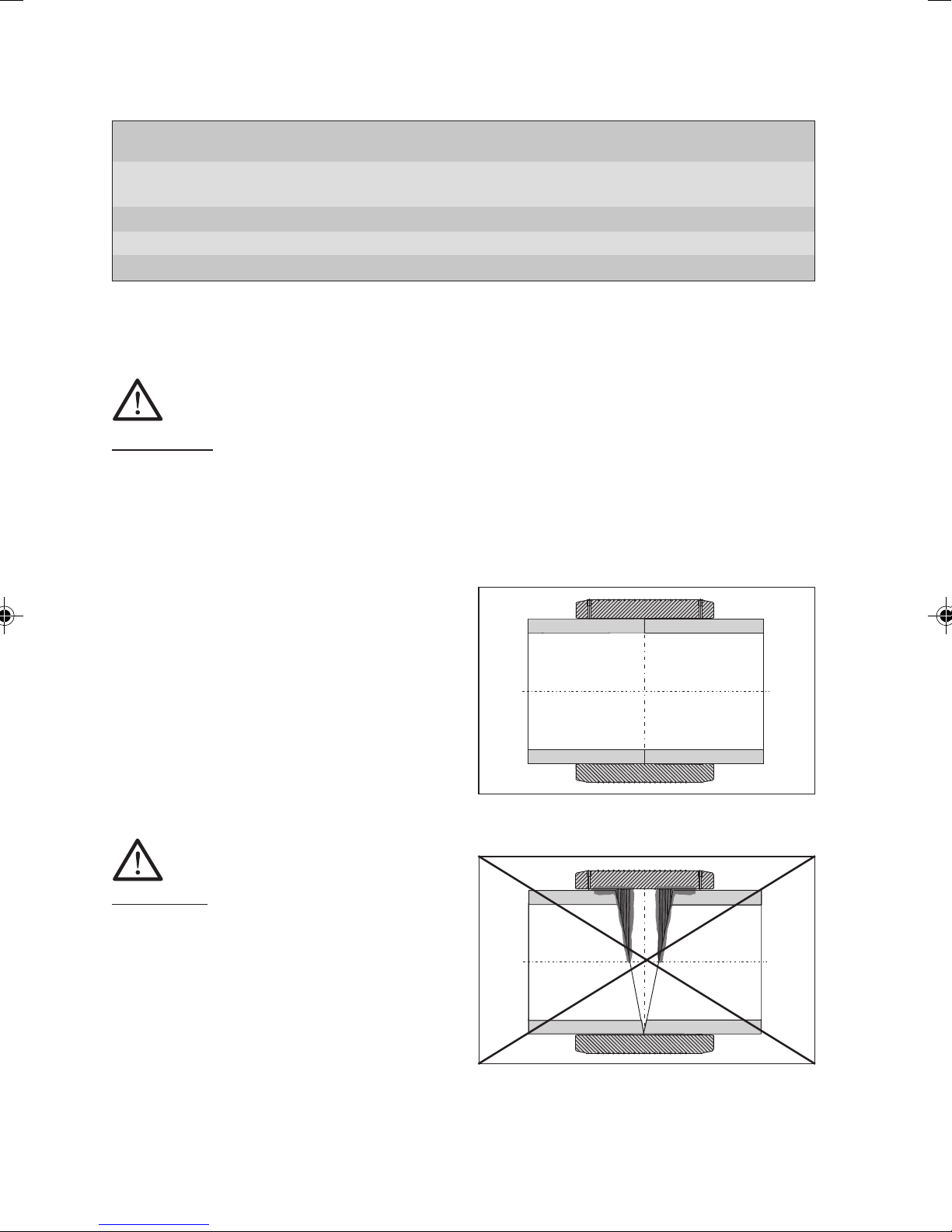
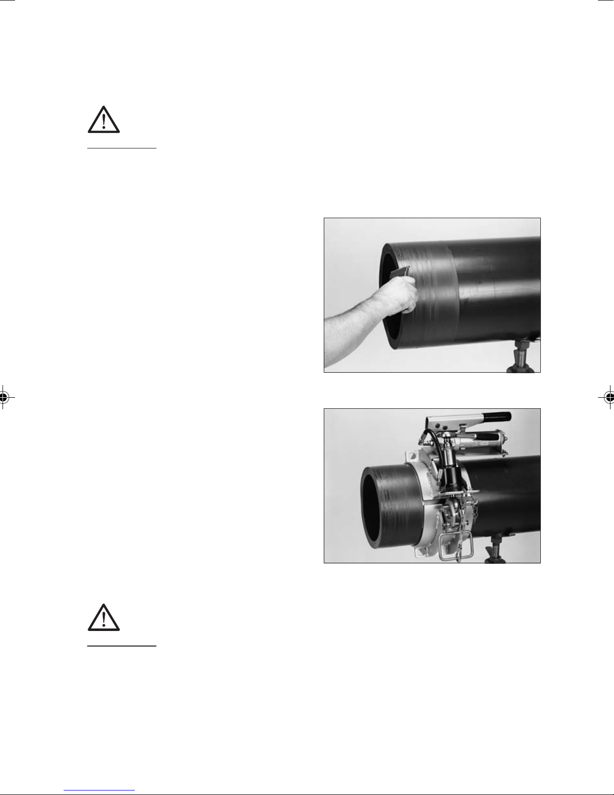
Cut off the pipe in a right angle
to the pipe axis (see Figure 1). A
suitable tool is a PE pipe cutter or a
saw with toothing suitable for
plastics.
Distinctive conical oblique pipeends
must be cut off, if necessary.
DANGER!
A non-rectangular pipe cutting
may cause the heating coil
partially not being covered by the
pipe which may result in
overheating, uncontrolled melt
formation or self-ignition (see
Figure 2).
Figure 1
Figure 2
6
4.2 Measure fusion zone, mark
with a FRIALEN® marker
and remove oxide layer
Fusion zone:
The length of the fusion zone
corresponds to half the length of the
coupler.
At first, remove contaminations from
the pipe. A processing allowance of
approx. + 5 mm in addition of the
insertion depth provides proof after
fusion that the oxide layer has been
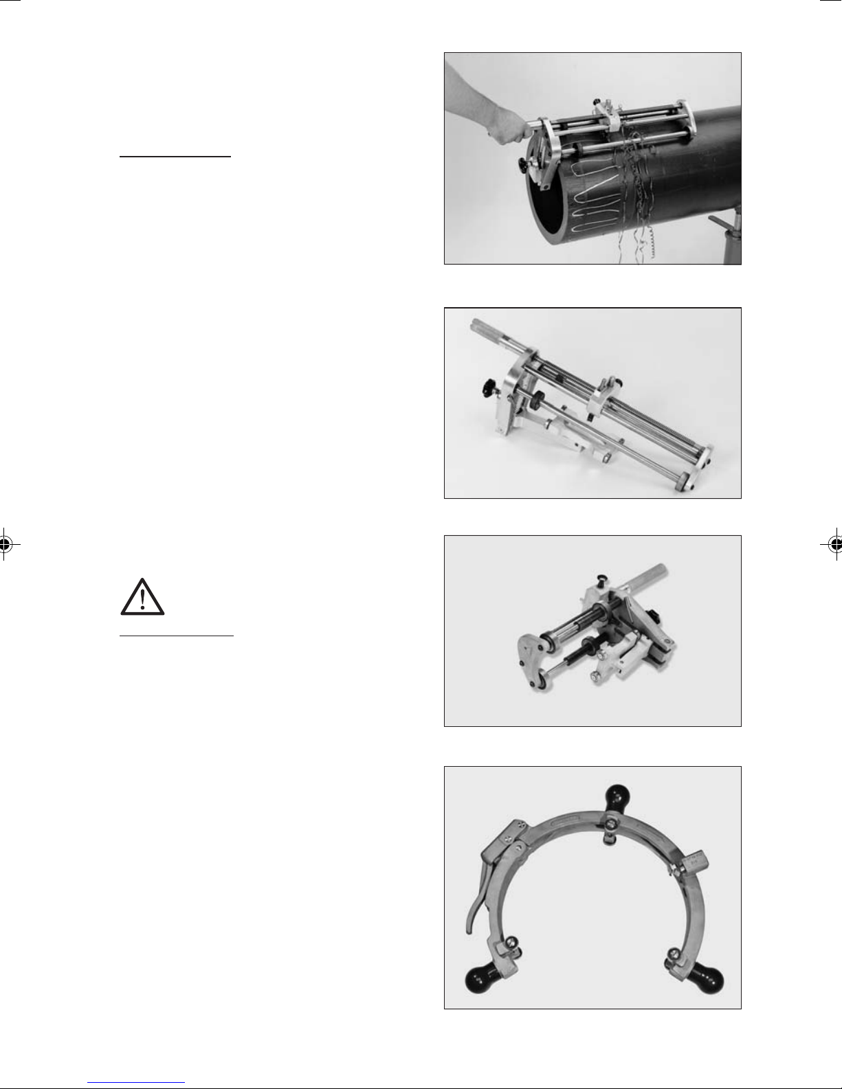
removed properly. Using a manual
scraper or FRIALEN® Scraper tools
(see Figure 4 a+b+c), the oxide layer,
which formed during on the surface
of HDPE pipes and spigot fittings
during storage, has to be removed
completely directly before the
assembly.
IMPORTANT!
The Scraper tool FWSG 710 S and
FWSG 710 L have proved themselves for a long time in use
application and serve for the
scraping of pipes in the dimension
area d 250 to d 710.
Figure 3
Figure 4a
Figure 4b
Besides, the FWSG 710 S scrapes
only half a sleeve length, so that it
is possible to scrape spigot
fittings. With the FWSG 710 L the
whole sleeve length is scraped to
make easier the assembly as a
slide-over coupler.
The scraper tools FWSG SE 250,
280 and 315 are proper for both,
preparation of couplers-, and
saddle assembly.
Figure 4c
7
WARNING!
If the oxide layer is not removed completely, inhomogeneous, leaking
fusion joints may result.
WARNING!
The FWSG 710 scraper tool must in all circumstances be used for fittings
from d 710.
A one-time, complete removal is sufficient (min. 0.15 mm).
Damages to the pipe surface as e.g. axial grooves or scratches may not be
located within the fusion zone.
WARNING!
An excessive swarf removal may result in an excessively large annular
gap which either cannot or only insufficiently closed by fusion (for the
remedy see item 4.8).
Please thus regularly check the condition of the blade at the manual
scraper and the wear of the scraper blade at the scraper tool. Worn blades
must be replaced (see FRIALEN® Info No. 1).
Scraper Tool Estimated swarf thickness (mm) Abrasion limit (mm)
FWSG 225 0.25 - 0.35 0.4
FWSG 710 0.30 - 0.40 0.5
FWSG SE 250 - 315 0.25 - 0.35 0.4
Please note that the indicated wearing margin applies to FRIALEN
Safety Fittings. Where appropriate please observe manufacturers’
indications.
Filing or sanding are not permitted because contaminations are
introduced.
For a control of the complete surface removal over the entire surface, we
recommend to apply marking (control) lines (see Figure 3). If during scraping of
the surface non-scraped areas occur at some points (e.g. in case of oval pipes),
these areas are to be reworked.
®
8
The processed zone is to be protected against dirt, soap, grease, subsequently
flowing water and unfavourable effects of weather (e.g. moisture, frost formation).
Do not touch the fusion zone again after scraping.
WARNING!
FRIALEN® Safety Fittings with integrated heating coils guarantee optimal
heat transfer through their exposed heating coils and may thus not be
scraped at the inside of the fitting.
4.3 External and internal
chamfering of the cutting
edge (See Figure 5)
For this purpose, the manual scraper
is a suitable tool. A good chamfer on
the outside diameter of the face of
the pipe will make it easier to fit the
coupler. Remove swarves from
within the pipe.
4.4 Restoration of irregular /
Figure 5
oval pipes
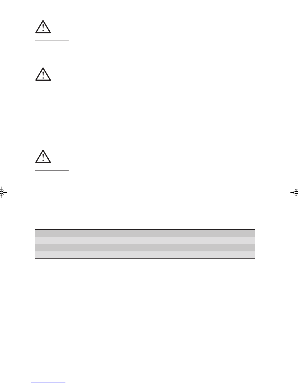
Pipes, in particular bundled coils and
drums, may loose their roundness
during storage. If the pipe out-ofroundness in the fusion zone area
exceeds 1.5% of d (outer diameter)
or is > 3.0 mm, these pipes must
be rounded in the fusion zone
area. Please use rounding clamps
for this purpose which are installed
at the end of the fusion zone (See
Figure 6).
Figure 6
WARNING!
For the installation of of fittings from d 710 rounding clamps for the
pipes need to be applied in all circumstances.
With UB couplers d 280 to d 450 the pipe may be adjusted to the coupler
following evaluation of the annular gap (> 1 mm) by using the pre-heating
barcode.
9
WARNING!
The pre-heating barcode must be applied when using fittings from d 500.
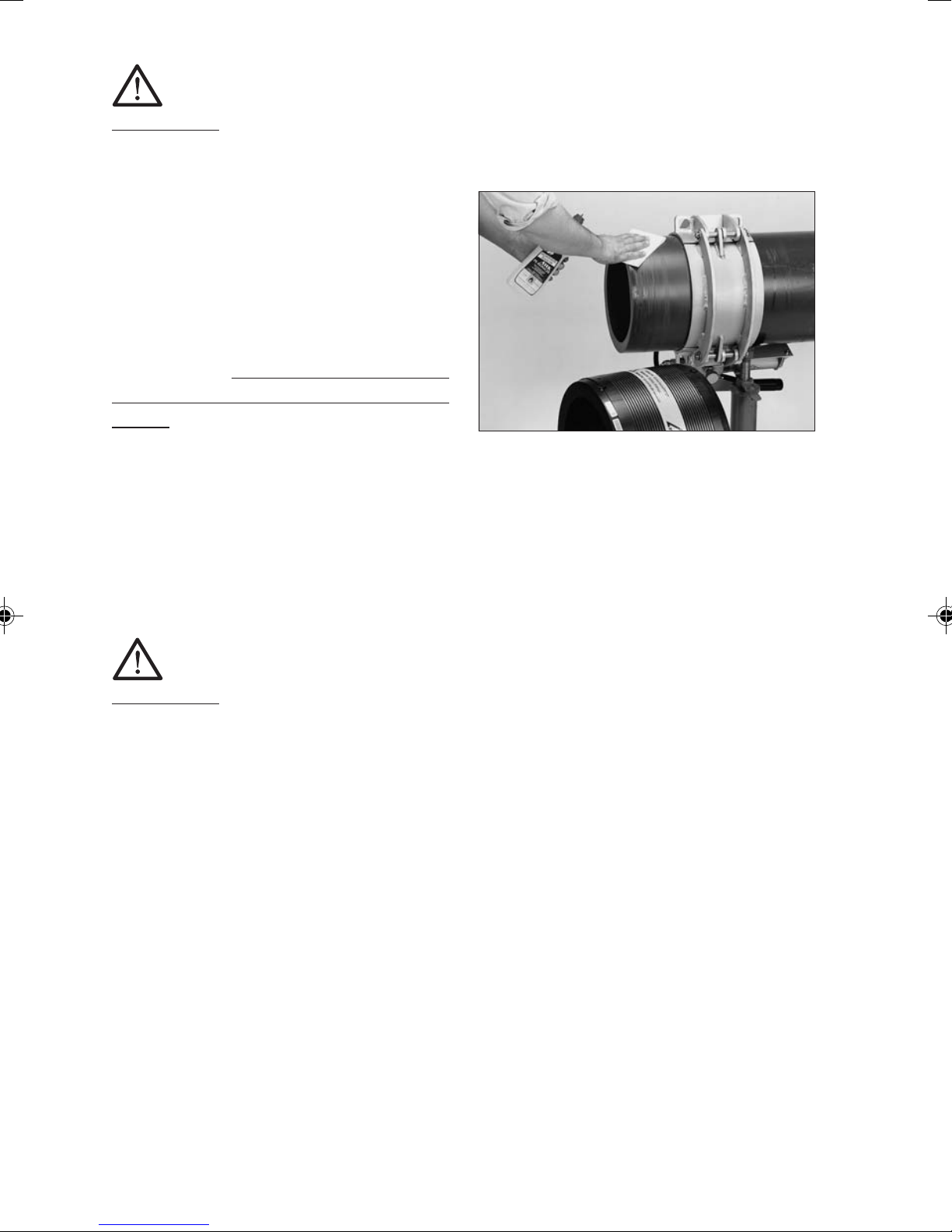
4.5 Cleaning
The surfaces of the pipes to be fused
and the interior surfaces of the
FRIALEN® Safety Fittings must be
absolutely clean, dry and free from
any grease. These areas are to be
cleaned with a suitable cleaning
agent and exclusively with ab-
sorbent, lint-free and non-dyed
paper directly before the assembly
and after scraping (see Figure 7).
Figure 7
We recommend PE cleaning agents which meet the requirements of the test
basis DVGW-VP 603, e.g. AHK cleaning agents.
When cleaning, ensure that no contaminations from the unscraped pipe
surface are introduced into the fusion zone.
WARNING!
When using alcoholic cleaning agents, the alcohol percentage must be
at least 99.8% according to DVGW-VP 603.
The cleaning agent must be completely evaporated before starting the
fusion process.
Now, using the FRIALEN® marker, re-mark the line (approx. 120 ° distributed around the circumference) to show the width of the fusion zone on the
pipe since this will have been removed by scraping and cleaning.
The joint surfaces must be clean and dry before installing the fitting. The
cleaned fusion zone should not be touched with bare hands. Moisture in the
area of the joint area, e.g. because of dew or frost, is to be removed using
suitable aids.
The fusion fitting is to be removed from the packaging only directly before
the planned processing. The packaging protects the fittings against external
influences during transport and storage.
10

4.6 Inserting push fit ends or pipe ends into the fitting.
When the FRIALEN® Safety Fittings and pipes are being assembled care
should be taken to ensure that the contact sockets are accessible to allow
connection of the fusion plug. Assembly can be assisted by tapping around the
face with a plastic hammer at the same time. When assembling do not tilt.
The worked insertion end must be pushed into the fitting up to the mark. If
necessary hydraulic rounding clamps should be used (see Figure 6).
Repeated scraping of the outer diameter might be necessary if the tolerance
is big. Repeated scraping may not be performed to remedy installation
problems due to out-of-roundness!
If the fitting cannot be slipped on without using force despite the above
described procedure, a repeated scraping is permitted. (see item 4.4).
A simple control of the high points is possible by installing the coupler and
evaluating the annular gap.
4.7 Ensuring a tension-free assembly of the components
All joints prepared for fusion must be tension-free. Pipes may not be positioned
in the FRIALEN® Safety Fitting under bending stress or self-load. After the
installation on the pipe ends, it must still be possible to move the couplers by
hand.
If required, the piping or the fitting is to be supported or suitable fixing
facilities are to be used. The tension-free fixing of the joint is to be maintained
until the cooling time stated on the barcode and in the table is reached. (see
item 4.9).
Before starting the fusion process, check again based on the markings
whether the position of the pipe insertion end in the FRIALEN® Safety Fitting
has shifted (correct, if required).
WARNING!
A non-tension-free or shifted joint
may result in an impermissible melt
flow and a defective joint during
fusion (see Figure 8).
Figure 8
11

4.8 Pre-heating for reducing the annular gap between coupler and
pipe.
WARNING!
Only use fusion units which have been approved by the manufacturer
with regard to their function for the processing of FRIALEN® Safety
Fittings. See DVS 2207-1.
Use FRIAMAT® fusion units only for FRIALEN® UB d 710!
Preheating barcode (see also instruction leaflet enclosed with the
component part)
The ring gap between the coupler and the pipe can be compensated for
to a certain extent by using a specifically matched preheating barcode
(Figure 9). The maximum bridgeable distance between the coupler and the
pipe may not exceed 3 mm across the entire circumference. For the coupler
mounted and centred at the pipe,
this means: Δ d ≤ 6 mm.
For relining slide-over couplers REM
d110/DN100 and d160/DN150, a
maximum gap of 2 mm applies. The
thermal reduction of tensions in the
joining area has also a positive
effect on the fusion result.
Figure 9
Procedure:
1. Preparation of the joining area corresponding to the FRIALEN® installation
instructions for large pipes and pipe network relining.
2. Centre the coupler on the pipe such that the ring gap across the
circumference is as equal as possible. If required, support the coupler.
3. Close the ring gap with adhesive tape to prevent heat losses.
4. Close open pipe ends (chimney effect).
5. Standard processing:
I. Preheating of first coupler side, record yellow barcode with FRIAMAT
electrofusion unit and start the process; then
II. preheating of second coupler side, record yellow barcode with
FRIAMAT® electrofusion unit and start the process; then
III. first coupler side: check the ring gap: if it is still too large, the
preheating can be repeated 2 x maximum. If ok: Start fusion of first
coupler side, (white barcode), then
IV. second coupler side: check the ring gap: if it is still too large, the
preheating can be repeated 2 x maximum. If ok: Start fusion of
second coupler side, (white barcode)
®
12

WARNING!
Between preheating and fusion, a waiting time is always required to
ensure heating through of the component parts. This waiting time
corresponds approximately to the preheating or fusion time, depending
on the dimension approx. 15-30 minutes. If only one coupler side is to
be processed, the waiting time between preheating and fusion is to be
observed.
If the waiting time is exceeded by more than the double time, the
described process is to be repeated.
4.9 Carrying out the fusion
WARNING!
Only use fusion units which have
been approved by the manufacturer with regard to their function
for the processing of FRIALEN
®
Safety Fittings. See DVS 2207-1.
Use FRIAMAT® fusion units only
for FRIALEN® UB d 710!
Figure 9a
For the fusion of the coupler d 800
please observe our FRIALEN® Info
No. 42.
The fusion parameters are contained in the main barcode affixed to the
FRIALEN® Safety Fitting. When using fully automatic fusion units (e.g.
FRIAMAT®), the parameters are entered into the fusion unit using the reader.
After reading of the barcode (see Figure 9a), the fitting data are to be
compared with the data shown on the unit’s display.
The subordinated barcode contains the data for component traceability (see
information). This barcode is only to be read if the component traceability
function is to be used. This requires suitable fusion units.
The fusable pipe series are listed in the SDR labelling on the label.
The fusion units automatically monitor the fusion process and control the
supplied energy in determined limits.
13

Information:
The fusion parameters are encoded on the barcode label in the form
of a 24-digit figure (top), the data for component traceability in the
form of a 26-digit column of numbers (bottom), and can also be
entered manually into the FRIAMAT® fusion unit using the emergency
entry mode.
Information:
Fusion units FRIAMAT® L and
FRIAMAT® LE are not suitable for
the fusion of large couplers.
For fittings with separate coils (see
Figure 10), each fitting side is to be
fused separately.
For fittings with continuous coil, both
fitting sides are to be fused simultaneously (see Figure 11).
FRIALEN® Safety Fittings are equipped with a swell indicator, this only
gives an indication that fusion has
taken place. This swell indicator
signalises the fusion process, by
changing its colour (red) and by
increase of volume. The proper
progress of the fusion process,
however, is only shown by the
fusion
unit.
After reading of the barcode, the
fitting data are to be compared with
the data shown on the unit’s display.
If they are identical, start fusion.
Please observe the operating instruction of the FRIAMAT® fusion
unit.
Figure 10
Avoid stress on the connecting spot.
14
Figure 11

WARNING!
Keep a distance of one meter to the fusion site during the fusion
process for general safety reasons.
The obtained actual fusion time is
to be compared with the target
fusion time on the unit and to be
noted on the pipe or the FRIALEN
®
Safety Fitting (See Figure 12).
With this identification it is ensured
that no fusion point is overlooked.
In case of doubt, a fusion can be
repeated. But the joint surfaces
must be cooled down to ambient
Figure 12
temperature before each renewed fusion. Please contact for this purpose
your local FRIALEN® sales engineer by phone or the FRIALEN® Hotline.
4.10 Cooling times.
The cooling time is
a) the time which is required to cool down the component to the temperature
which facilitates the movement of the joint. This time is also listed on the
barcode and is identified by CT.
b) the time which is required to cool down the component to the temperature
which facilitates the application of the full test or operating pressure. This is
classified into pressure volumes of up to 8 bar and > 8 bar.
WARNING!
When inserting piping (e.g. relining) it is the cooling time before pressurising which is important.
Diameter Cooling time in minutes for FRIALEN
in mm couplers and fittings
CT Up to pressurising Up to pressurising
until the joint at up to 8 bar at > 8 bar
may be moved
250 – 355 30 75 100
400 – 710 40 95 120
800 90 200 240
®
15

Information:
A piping may only be commissioned after successful pressure test (see
EN 805, EN 12007 and DVGW G 469, W 400). The guidelines of the
DVGW leaflets for pressure tests, the European standards or the
country-specific regulations are to be observed.
Information:
The detachment of the outer armouring wire during the cooling down
stage is caused by the thermal expansion characteristics of the fused
joint and does not present a problem.
5. Saddle parts - Top Loading
FRIALEN® TL saddle parts are used with pipes from SDR 17 to SDR 11
from d 250 mm. The processing occurs with the FRIATOP Clamping Unit
(Figure 15b).
5.1 DAA-TL Pressure Tapping Tees - Top Loading, d 250 - 315 (400)
FRIALEN® DAA-TL Pressure Tapping Tees Top-Loading are suitable for
fitting as branch connectors onto unpressurised or pressurised pipelines.
WARNING!
FRIALEN® pressure tapping valves
≥ d 355 mm may be processed
using only SDR 17 and SDR 17,6
pipes due to tapping technique.
Processing temperature: between
0 °C and 45 °C.
Figure 13
16

5.1.1 Measuring of fusion zone of
the pipes (and the lateral
outlet spigot), marking and
removing oxide layer
The fusion zone: is the area of pipe
covered by the saddle; for a side outlet
it is the insertion depth on the smooth
pipe spigot. The oxide layer in the
area of the fusion zone, which has
formed on the surface of the HDPE
pipes during storage, must be totally
removed with a hand scraper or a
scraper tool (e.g. FWSG SE) immediately before assembly (See Figure
14).
A processing allowance of several
millimetres in addition to the covered
area provides proof after fusion that
the oxide layer has been properly
removed from the pipe.
Figure 14
WARNING!
If the oxide layer is not removed
Figure 14 a
completely, leaking fusion joints
may result.
Worn blades of the scraper tool and manual scraper must be replaced.
A one-time, complete removal is sufficient (min. 0.15 mm). A uniform surface
without flattening and material grates at the pipe diameter should be the
result.
WARNING!
Filing or sanding of the pipe is not permitted because contaminations
are introduced.
17

For a control of the complete surface removal over the entire surface, we
recommend to apply marking (control) lines (see Figure 13). If during scraping
of the surface non-scraped areas occur at some points, these areas are to
be reworked.
The processed zone is to be protected against dirt, soap, grease,
subsequently flowing water and unfavourable effects of weather (e.g.
moisture, frost formation).
5.1.2 Cleaning
The surfaces of the pipes to be fused and the interior surfaces of the
FRIALEN® DAA-TL Pressure Tapping Tees Top-Loading must be
absolutely clean, dry and free from any grease. These areas are to be
cleaned with a suitable cleaning agent and exclusively with absorbent,
lint-free and non-dyed paper directly before the assembly and after
scraping.
We recommend PE cleaning agents which meet the requirements of the test
basis DVGW-VP 603, e.g. AHK cleaning agents.
When cleaning, ensure that no contaminations from the unscraped pipe
surface are introduced into the fusion zone.
WARNING!
When using alcoholic cleaning agents, the alcohol percentage must be
at least 99.8% according to DVGW-VP 603.
The cleaning agent must be completely evaporated before starting the
fusion process.
Subsequently, re-apply marking line for the fusion zone width with the
FRIALEN® marker because this line was removed during scraping and
cleaning. The joint surfaces must be clean and dry before installing the
fitting. The cleaned fusion zone should not be touched with bare hands.
Moisture in the area of the joint area, e.g. because of dew or frost, is to be
removed using suitable aids.
18

The fusion fitting is to be removed
from the packaging only directly
before the planned processing. The
packaging protects the fittings
against external influences during
transport and storage.
5.1.3 Assembly
- Place the saddle onto the prepared
surface of the pipe.
- Fit the adapter of the FRIATOP
clamping device (Figure 15a).
- Fit the clamping device as directed
in the Operating Instructions (Figure
15b).
WARNING!
For pressure tapping tees and
pressure tapping valves, the
factory drill setting may not be
changed before starting the fusion
process.
Figure 15a
5.1.4 Carrying out of fusion
When fusing Pressure Tapping
Tees to media-carrying pipings, the
following operating pressures may
not be exceeded until the pipe has
cooled down completely:
Figure 15b
19

Pipe material PE 80 PE 100
SDR 17 11 17 11
Maximum permissible working pressure in bar
Gas pipe 2 5 5 10
Water pipe 8 12.5 10 16
WARNING!
Only use fusion units which are authorised by their manufacturer to
process FRIALEN® Safety Fittings as part of their function. See DVS
2207-1.
The fusion parameters are contained in the main barcode affixed to the
FRIALEN® Safety Fitting. When using fully automatic fusion units (e.g.
FRIAMAT®), the parameters are entered into the fusion unit using the reader.
After reading of the barcode, the fitting data are to be compared with the
data shown on the unit’s display. If they are identical, start fusion. Please
observe the operating instruction of the FRIAMAT® fusion unit.
The fusion units automatically monitor the fusion process and control the
supplied voltage in determined limits.
The swell indicator only indicates to the performed fusion process. The
proper fusion process is, however, only indicated by the fusion unit!
WARNING!
Keep a distance of one meter to the fusion site during the fusion
process for general safety reasons.
The obtained ACTUAL fusion time is to be compared with the target
fusion time on the unit and to be noted on the pipe or the FRIALEN
Safety Fittings.
With this identification it is ensured that no fusion point is overlooked.
After the fusion process has finished always maintain the jointing
pressure for a 10 minute cooling period!
®
20

5.1.5 Tapping and application of the test and operating pressure
The following waiting times are to be observed:
Diameter Cooling time in minutes for FRIALEN
in mm Saddle fittings
Up to pressurisation CT
via outlet Up to
tapping
≥ 250 50 60
®
The cooling time CT stated on the components corresponds to the cooling
time until tapping.
WARNING!
If the waiting times are not observed, leaking fusion joints may result. The
general installation instructions must be observed before tapping.
5.1.6 Tapping of Pressure
Tapping Tees
Remove blanking plug. Turn the drill
down up to the lower stop using the
matching FRIALEN® activating key
(SW 19) (See Figure 16).
Turn the drill backwards up to the
upper stop. Position the blanking
plug and turn down the FRIALEN
®
activating key until the collar of the
plug slightly touches the front face
of the drill spigot.
Subsequently, turn back the plug
half a turn to relieve the O-ring
tension.
WARNING!
If the collar is excessively tightened, the plug may break or the hexagonal seat may be overwound. In this case, the plug has to be replaced.
We recommend closing the tapping dome with a fusion cap K. The
required scraping and cleaning are to be performed (see items 4.2 - 4.8).
Figure 16
21

5.1.7 Tapping of DAV-TL pressure tapping valves d 250 - 315 (400)
(Figure 17)
WARNING!
Because of tapping requirements,
the FRIALEN-pressure tapping
valves ≥ d 355 can only be installed
on pipes with SDR 17.
Installation, fusion and cooling times
as 5.1.3 et seq.
Tap by turning square spanner
clockwise up to lower end position.
The valve is now closed. In order to
open the valve, the tap must be moved
Figure 17
anti-clockwise up to the end position.
After arriving the end position turn
back approx. half a rotation.
The metal end points for the ‘open shut’ positions of the valve lead to a
distinctly noticeable increase in the activating force. As sealing takes place
in the closed position using a radially injected O-ring, it is not necessary to
apply a great deal of pressure when closing the valve.
Install the FRIALEN Installation Kit EBS on the 14 mm square of the DAV-TL
and secure the splint against pull out. Set the required overlapping height on
telescoping frame. Telescoping frame may be adjusted by sliding scale and
will stop securely at any point. The FRIALEN® EBS is technically perfectly
adapted to the FRIALEN® DAV-TL.
22

5.2 VAM-RG-TL Valve Tapping Saddles d 250 - 315 (560)
5.2.1 Assembly
The preparation of the installation
and the fusion process is made
analogue to the FRIALEN® Pressure
Tapping Tee (see 5.1.1 to 5.1.4).
WARNING!
The fusion range of the saddle
covers the dimensions d 250 up
to d 560. If necessary application
Figure 18
technology restrictions must be considered by drill tool (usually
applicable until d 315 SDR 11).
Restrictions concerning the application must be considered, e.g. length
of drilling tool. Details of these components, given by manufacturer,
have to be regarded.
The cooling times are to be observed (see item 5.1.5 Pressure Tapping Tee).
The fitting is drilled using a suitable close-off device or fitted with a valve in
accordance with the relevant Fitting Instructions from the different valve
manufacturers. The preparation and conduct of the pressure test are carried
out in accordance with the details given by the valve manufacturer.
The threaded components fitted at the factory must be secured with a
spanner to prevent them from twisting.
Care should be taken to ensure that the insulation work is carried out in
accordance with the regulations (DVGW Standard Publication).
5.3 SPA-TL Shut off Saddles
Top-Loading d 250 - 315 (560)
5.3.1 Assembly
WARNING!
The fusion dimensions of the component includes d 250 - d560. If
necessary application technological restrictions have to be regarded.
For example by borer tool or balloon, normally applicable up to d 315
SDR 11. Details of these components, given by manufacturer, have to
be regarded. Processing temperature: between 0 °C and 45 °C.
23

FRIALEN® Shut-off Saddles (see
Figure 19) are prepared for
installation and fused analogue to
FRIALEN® Pressure Tapping Tees
(see Chapters 5.1.1 – 5.1.4). The
tapping of the pipe can be made
after cooling down (see item 5.1.5)
and observing the installation instructions of the tapping/shut-off
saddle installation equipment of the
relevant manufacturer.
Installing the brass plug
The plug is to be installed up to the
stop; the O-ring must seal in the
dome. The required torque of
approx. 150 Nm can be achieved
through a lever. A visual control
takes place (Figure 20). A torque
screwdriver is not necessary.
Figure 19
After fitting the brass plug either the
plastic nut must be screwed on or a
FRIALEN® cap for Shut off Saddles must be fused on, ensuring that
the usual scraping and cleaning
work is carried out (see Figure 21).
5.4 SA-TL Spigot Saddles
Top-Loading d 250 - 560
5.4.1 Assembly
The preparation of the installation
and the fusion process is made
analogue to the FRIALEN® Pressure
Tapping Tee (see 5.1.1 - 5.1.5).
Figure 20
Figure 21
24
Figure 22

WARNING!
The tapping is made with commercially available tapping units in an
unpressurised state with or under pressure using shut-off valves.
We recommend the tapping unit of the company of Hütz + Baumgarten,
Remscheid (www.huetz-baumgarten.de), especially designed for this
purpose.
Please ask our FRIALEN® Application Engineering Department.
The manufacturer’s installation instructions are to be observed.
5.5 VSC-TL Repair Saddle
Top-Loading d 250 - 560
5.5.1 Assembly
For localised damage to the pipe at a
single point the damaged spot can be
sealed off with a plug and then fused
with the repair Saddle Top-Loading.
The preparation of the installation
and the fusion process of the
Figure 23
individual half shells is made
analogue to the FRIALEN® Pressure
Tapping Tee (see 5.1.1 - 5.1.5).
WARNING!
Care must be taken to ensure that during assembly the damaged or
deformed point on the pipeline lies in the centre of the heating element.
Fusion with escaping media is not permissible.
25

5.6 AKHP-TL Tapping Ball Valves d 250 - d 560
AKHP-TL Tapping Ball Valves allow
the drilling of unpressurised or
pressurised pipelines.
WARNING!
The fusion zone of the component
includes the dimensions d 250d 560. If necessary application
technological restrictions have to
Figure 24
be regarded. For example by borer
tool or balloon, normally applicable up to d 315 SDR 11. Details of these
components, given by manufacturer, have to be regarded.
5.6.1 Assembly
The preparation of the installation and the fusion process of the tapping ball
valve AKHP is made as saddle component analogue to the FRIALEN
Pressure Tapping Tee (see items 5.1.1 - 5.1.5).
®
INFORMATION:
For a leakage-free tapping of pressurised pipings, we recommend the
tapping unit of the company of Hütz + Baumgarten, Remscheid
(www.huetz-baumgarten.de). Please ask our Application Engineering
Department.
The telescopic FRIALEN-actuation key BS is particularly designed for the
technical and geometrical requirements of the KHP ball valve.
6. Pipeline relining
6.1 Procedures and areas of application
Defective old pipelines made of cast iron, steel or other conventional materials
can be renovated by drawing in an HDPE pipe, as an alternative to laying new
pipes.
Standard pipes are used for the relining process and are joined using
suitable FRIALEN® Safety Fittings.
26

For the so-called close-fit process (lining with precisely fitting pipes),
however, the pipes which are used have a cross section which has been
changed in the manufacturing process (e.g. U-liners) or on the building site
itself (e.g. Swage lining). The outside diameter of these pipes is matched to
the inside diameter of the old pipeline and thus deviates from the standard.
The ends of each renovated section of pipeline can be fused with FRIALEN
REM Relining Slide-over Couplers.
At points where it is scheduled to fuse on a coupler or a saddle the relining
pipe should be sized to the nominal inside diameter during the reshaping by
fitting half shells.
6.2 REM Relining Adapter Couplers
One end of the REM Relining Adapter Coupler (Figure 25) is matched to
the dimensions of the pipes used for
this process. The other end corresponds to the standard pipe size. This
allows renovated sections of pipeline
to be connected using fitted pieces of
standard pipe. The fittings are used
like slide-over couplers.
Figure 25
®
6.3 Fitting and fusion
6.3.1 Relining using HDPE standard pipes
When joining standard pipes the appropriate FRIALEN® Safety Fittings are
used. The fitting and fusion is carried out in a similar fashion to that in
item 2. For couplers > d 250 mm preheating in accordance with item 4.8 is
recommended when there are larger annular gaps.
6.3.2 Close-fit relining
After the renovation the HDPE pipes used will often exhibit deviations both in
their diameter and from the ideal round shape in the area of the proposed
joint. Depending on the characteristics of the pipe the joint can be made using
a preheating code, and also in conjunction with a support sleeve or a pipe
expander tool.
27

6.3.3 Pre-heating: Procedure see
item 4.8
6.3.4 Support sleeve
In case of larger deviations in shape
or size on the ends of the pipes in the
area of the joint the use of support
sleeves is recommended (Figure 26).
The fitting can then be used as a
slide-over coupler.
For fitting the support sleeve a suitable
pipe expander tool has to be employed
(Figure 27). Before using the pipe
expander tool deviations in shape
must be taken into account. The
expander shells should be positioned
to give an optimum rounding effect.
Figure 26
Pipe expander tool
The design of the support sleeve is
dependent on the medium flowing,
the material and the pipe size.
Figure 27
The fitting of coupler and sleeve will
be made easier if the pipe tolerances
are taken into account when deciding
on the size. The use of preheating in
accordance with item 6.3.3 will
then be essential.
6.3.5 Use of a pipe expander tool
as a temporary support
sleeve
Figure 28
If a support sleeve is not wanted the
coupler can be fused using a suitable
pipe expander tool, matched to the
size of the pipe. Use of the preheating barcode (see item 6.3.3) is particularly
important to reduce the stresses in the pipe. The tool must remain in place
during the fusion process and until the cooling period has passed.
28

6.4 Cooling times
For cooling times item 4.10 is applicable.
6.5 Relining fittings and clips
(top loading)
When fitting saddle components
(Figure 29) care must be taken with
any ovality or flattening of the HDPE
pipe. In order to achieve a uniform
Figure 29
surface pressure, and thus a proper
fusion, the radius of curvature on the inner liner at the site of the proposed
joint must correspond to the diameter range d of the moulded component
being used. If necessary the saddle must be brought into line either axially or
radially.
The assembly of the saddle components occurs according to items 5.1.1
to 5.1.6
Before the renovation the old pipe should be cut away at the point where a
moulded saddle component is to be fused to the inner liner pipe. The pipe
diameter will be brought to size at the proposed jointing point by fitting half
shells.
When fitting a house connection at some later point access to the inner liner is
gained by using a window cutter to get through the old pipe.
29

7. Update of these assembly instructions
Further operating and assembly instructions are available:
- FRIALEN® Safety Fittings for House Service
and Supply pipings up to d 225
- FRIAFIT® Sewage System
- FRIAMAT® Electrofusion Units
- FRIATOOLS® Scraper Tools
- FRIATOP Clamping Unit
- FWFIT Clamping and Tapping Tool
These technical statements are regularly revised to be up-to-date. The date
of the last revision is stated on the document. For an updated version of the
operating instructions, please visit our website www.frialen.com on the
Internet. You will find the “Download” page on the navigation bar. This page
contains our updated operating instructions as pdf documents. We will also
mail them to you on request.
30

31

FRIATEC Aktiengesellschaft · Technical Plastics Division
P.O.Box 71 02 61 · D-68222 Mannheim
Phone: +49 621 486-1486 · Fax: +49 621 479196
E-Mail: info-frialen@friatec.de · www.frialen.com
32
2104/8e · II.08 · Update: 26.02.08
 Loading...