

Friant & Associates Interra Installation Manual

Interra Installation Manual
to install the Friant
Interra panel system
Instructions
Friant & Associates, LLC

Table of Contents
Getting Started
Introduction ��������������������������������������������������������������������������������������������������3
General Tools, Staging & Safety ��������������������������������������������������������� 4
Before Installation ��������������������������������������������������������������������������������������5
A/B Style Frames ���������������������������������������������������������������������������������������6
Frame Connection Point Locations ��������������������������������������������������7
Frame Assembly & Connectors
Frame to Frame Assembly ��������������������������������������������������������������������8
Frame to Frame of Dierent Heights �����������������������������������������������9
Stacking Frame Installation �����������������������������������������������������������������10
Stacking Frame to Stacking Frame Installation ������������������������� 11
Door Frame Installation ������������������������������������������������������������������������ 12
Frame to Connector Assembly ���������������������������������������������������������13
Frame to Connector Assembly: 2-Way, 3-Way 4-Way ���������� 14
Stacking Frame to Connector Installation ����������������������������������� 15
Other Connectors & Finished Ends
Wall Strips ����������������������������������������������������������������������������������������������������16
Tile Adapters ���������������������������������������������������������������������������������������������� 17
Wall Start ������������������������������������������������������������������������������������������������������18
Frame Finished End Installation�������������������������������������������������������20
Finished End Change of Height Installation�������������������������������� 21
Trims & Top Caps
A/B Base Trim �������������������������������������������������������������������������������������������24
Top Cap Installation �������������������������������������������������������������������������������29
Glass Top Cap Installation, Center & End Cap ��������������������������30
Tiles
Fabric Tile����������������������������������������������������������������������������������������������������46
Fabric Tile to Floor ���������������������������������������������������������������������������������47
Window Tile �����������������������������������������������������������������������������������������������48
Markerboard Tile ��������������������������������������������������������������������������������������49
Rail Tile ���������������������������������������������������������������������������������������������������������50
Upper Components
Straight Front Half Height Shelf �������������������������������������������������������51
Sliding Door Overhead Cabinet ������������������������������������������������������� 52
Upmount Sliding Overhead Cabinet ���������������������������������������������54
Radius Front Half Height Shelf ��������������������������������������������������������� 55
Pneumatic Overhead Cabinet �����������������������������������������������������������56
Upmount Pneumatic Overhead Cabinet ������������������������������������� 57
Frameless Glass Installation ���������������������������������������������������������������58
Wire Manager ��������������������������������������������������������������������������������������������59
Task Lights ������������������������������������������������������������������������������������������������� 60
Worksurfaces & Legs
Worksurface: Rectangular ������������������������������������������������������������������� 61
Worksurface: Corner ������������������������������������������������������������������������������ 62
Open Metal Leg ���������������������������������������������������������������������������������������63
Square Post Leg ��������������������������������������������������������������������������������������64
Square Metal P-Leg ��������������������������������������������������������������������������������73
Square Metal Leg Triangle Frame ��������������������������������������������������� 74
Triangle Leg with Frame Support Bar ������������������������������������������65
Laminate End Panel �������������������������������������������������������������������������������68
Electrical
Wiring Diagram: Ceiling & Base �������������������������������������������������������32
8-Wire Electrical, Base Feed Installation ������������������������������������� 33
Ceiling Power Pole ����������������������������������������������������������������������������������34
8-Wire Electrical, Baseline Power Retro ��������������������������������������35
Power Connection: 2-Way, 3-Way, 4-Way �����������������������������������36
Beltline Power Retro ����������������������������������������������������������������������������� 40
In Frame Power Jumper ����������������������������������������������������������������������� 41
Beltline Power Connection �����������������������������������������������������������������42
Power Connection: Panel Through Post ��������������������������������������43
Receptacle Installation �������������������������������������������������������������������������44
Base Cover Installation ������������������������������������������������������������������������� 45
Lower Storage
Pedestals �����������������������������������������������������������������������������������������������������69
Lateral Files ������������������������������������������������������������������������������������������������70
Laterals Counterweight Installation ������������������������������������������������ 71
Interra 120° Build-out ���������������������������������������������������������������������������� 72
2

Interra System Installation Manual
Introduction
The Interra System Installation manual provides the necessary instruction
for the safe installation of the Interra System for:
• The Installers with visual and written instructions.
• The End Users to ensure continued safe use of the product when
maintaining and reconfiguring the product.
To ensure proper installation of the product, the Interra System requires
layout and wall supports as specified in this manual. Reconfiguration
of the product and additions to an installation must be performed per
the instructions in this manual to ensure the continued safe use of the
product. Friant & Associates, LLC does not assume any responsibility for
product that is altered in any way.The Interra System is composed of full
and/or partial height Walls, Support Cabinets, Wall Mounted and FreeStanding components, and accessories.
The Interra System is considered to be portable furniture; therefore,
subject to applicable local Fire, Electrical and Building Codes. Check with
local authorities prior to installation.
ELECTRICAL STATEMENT: Friant’s Interra System Electrical Distribution
System is listed with the Underwriters Laboratories, and complies with
the National Electrical Code, ANSI/BIFMA 70. Check with local authorities
prior to installing the product.
NOTE: To ensure proper installation of the product, frames
must be leveled during the installation process.
WARNING: Failure to follow the instructions
in this manual can result in product damage,
personal injury, or death.
Friant | Interra Installation Manual
3

General Tools, Staging & Safety
General Tools
Thefollowingtoolsarenecessaryforeldassemblyandinstallation
of Friant’s Interra product:
• allen wrench 1/4”
• #2 phillips head screwdriver
• #3 phillips head screwdriver
• screwdriver, med slotted
• measuring tape (25’ or more)
• rubber mallet or dead blow mallet
• carpenter’s level (48”)
In addition, the following tools will help speed up installations:
• drill (12v or more)
• set of drill bits
• set of screw bits #2 and #3
• 1/4” allen bit for drill
• wrench open end 10 mm (long handle is best)
• pliers
• carton knife
• ratchet head with 1/4” allen bit
• 6’ step ladder
• material handling carts
Safety
• Please note all warnings, as
these are for your safety�
• Always use proper tools when
installing�
• Keep your work area clean,
clutter-free and safe during
installation�
• Use eye protection when
working under a workstation or
when working with tools�
• Many products weight more
than 35 pounds, so use two or
more people to safely lift, carry
and install the products�
• When using tools, extension
cords or ladders, use them in
accordance to OHSA guidelines�
• Work safe, work smart�
Staging
Inaneorttomakeyourprojectrunmoresmoothly,thefollowingis
recommended:
1. Check in and count all products for accuracy and damage prior to
the delivery truck leaving. Note any damages or shortages on the
Bill of Lading before signing.
2. Notify the factory immediately of any shortages or damages (with
photo to document).
3. Unload all products into a staging area on your job site and sort by
product number.
4. Keep and maintain a clutter-free staging area — it will help speed up
your assembly.
5. Protect all building walls with furniture pads or cardboard where
productisleaningagainstthemorinhightracareas.
Friant | Interra Installation Manual
4
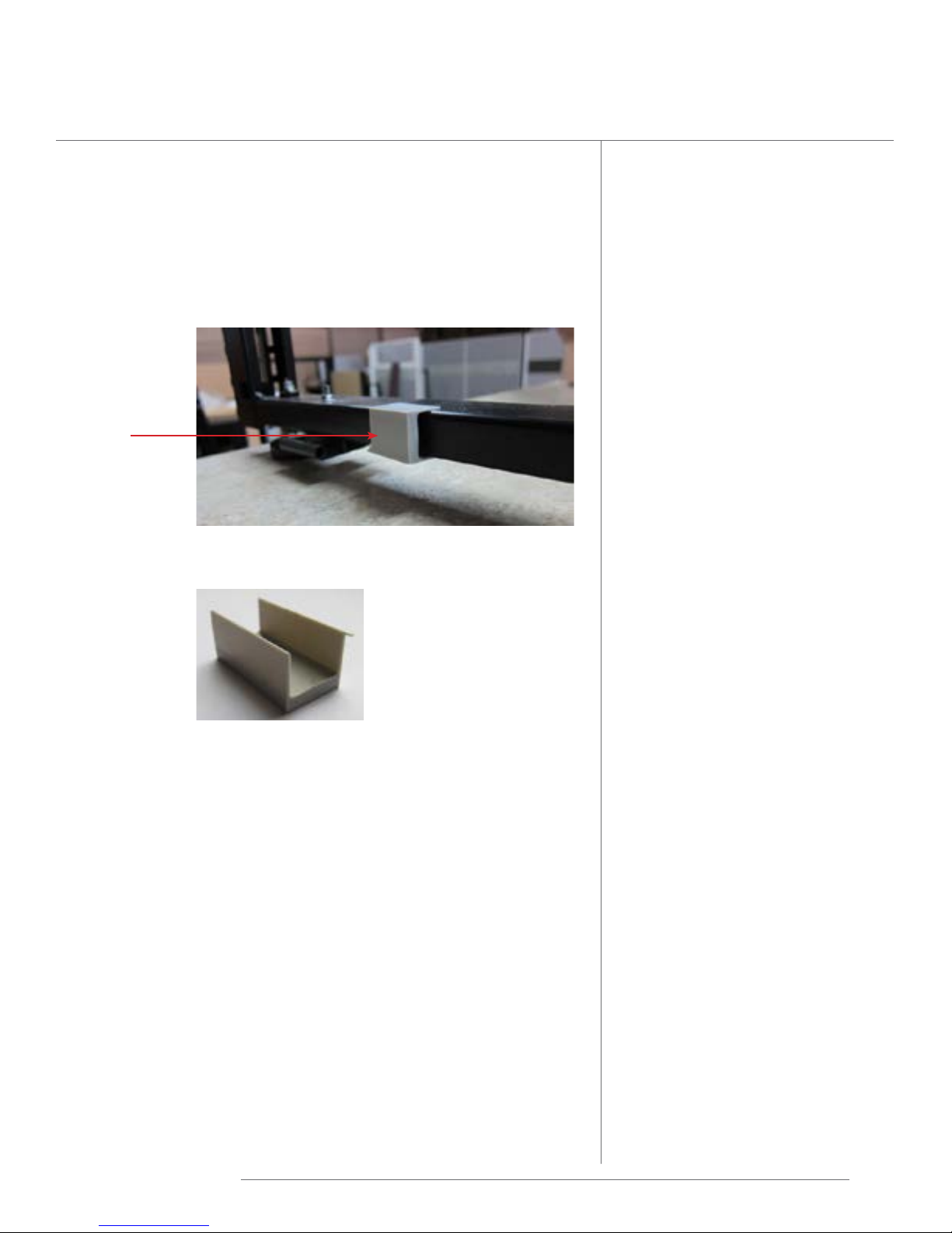
Before Installation
Remove shipping spacers
Some sizes of Interra frames ship with stability bar at the top
corners. All sizes ship with gray plastic spacers at the bottom.
These are on the frame for shipping purposes only and must be
removed before installation.
spacer
Spacers on the bottom of the frame can be removed by
pullingthemotheframe.Theydonothavescrews.
Friant | Interra Installation Manual
5
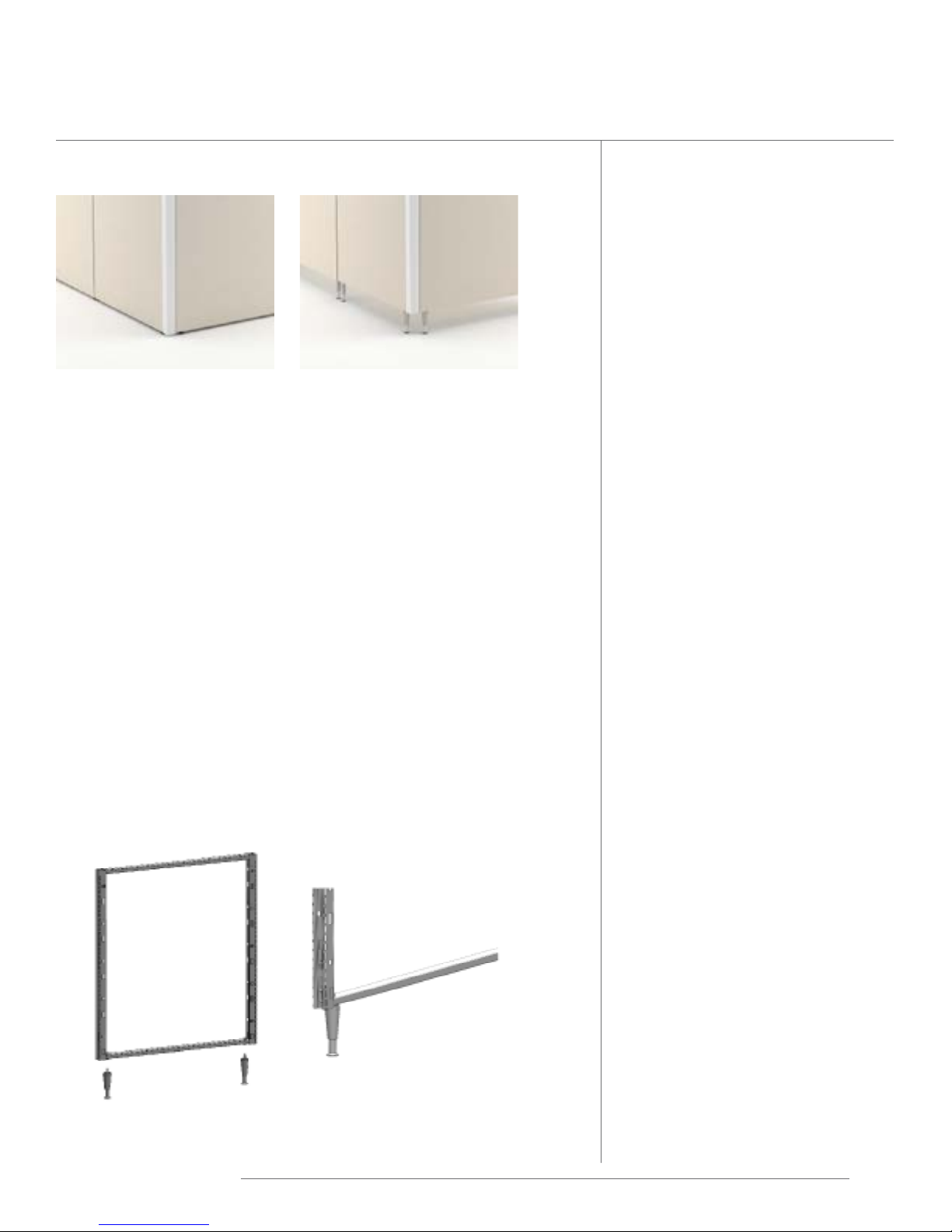
A/B Style Frames
A-Style B-Style
(tiletooorshown)
A-Style Frame
tiletooorstyleorbasecoverstylewithadjustableglides
• Ships assembled with adjustable glides at bottom.
• Be sure that the glides are all the way in the bottom of the frame.
Iftheoorisuneven,glideadjustmentshouldbemadeduring
assembly of the product.
B-Style Frame
open base style with adjustable legs
• Ships unassembled.
• Prior to beginning the installation, attach legs to frame by inserting
the leg and tightening the bolt.
• Leg is adjustable. Be sure the legs are all the way in at their lowest
point.Iftheoorisuneven,glideadjustmentshouldbemadeduring
assembly of the product.
Friant | Interra Installation Manual
6
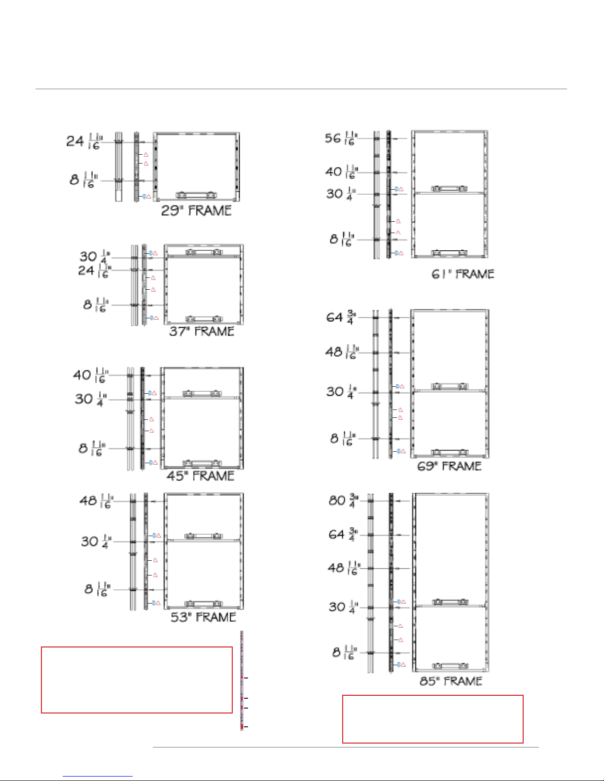
Frame Connection Point Locations
For Frame to Frame or Frame to Connector. Shown below with beltline power.
Power & data distribution cut outs are
approximately 2.75” tall and are located
approximately 2.5”, 16”, 22”, & 33” from the
bottom of the frame.
in product damage, personal injury, or death.
Friant | Interra Installation Manual
33”
22”
16”
2.5”
WARNING: Failure to follow the
instructions in this manual can result
7
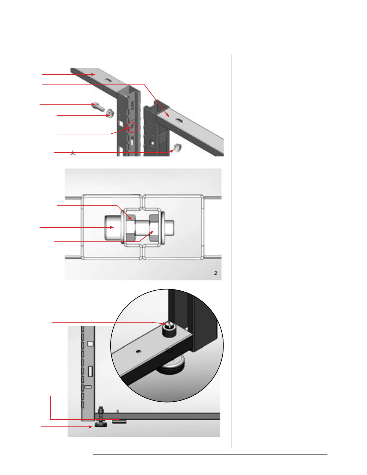
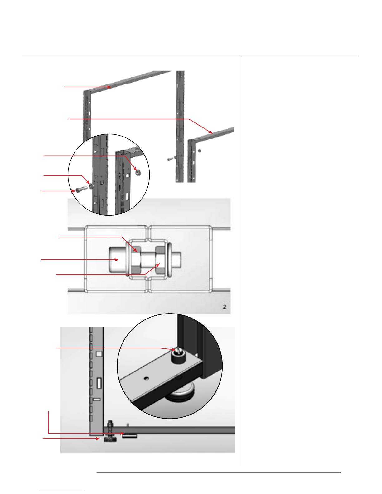
Frame to Frame Assembly
Frame
Frame
Bolt
Alignment
Nut
Hexagonal
Cutout
Threaded
Nut
Alignment
Nut
Bolt
Threaded
Nut
Use Frame to Frame packages to
connect frames of equal or dierent
heights in a straight line� Frame to
Frame package consists of: a bolt,
alignment nut, and threaded nut�
Use the quantity of Frame to Frame
connection packages needed per the
chart below, and see Frame Connection
Point Location page�
Frame Connection points per height:
Height Connections
29” 2
37” 3
45” 3
53” 3
61” 4
69” 4
85” 5
Frame to Frame of the same
height
1� Frames are connected to each other
by means of connecting bolts� A
connecting bolt consists of: a bolt, a
alignment nut and a threaded nut�
Glide
Adjustment
Base cover
holder
Glide
Correct Assembly
2� Bring frames to be connected to-
gether� Insert alignment nut in the
hexagonal cutout in frame number 1�
3� Insert threaded nut in the hexagonal
cutout in frame number 2�
4� Insert bolt through the alignment
nut and secure to threaded nut�
5� Prior to tightening the bolt, insert
the correct number of connecting
bolts, as per the table above and at
the location indicated in the Connection Point Location reference
page�
6� After all connecting bolts are in-
serted, tighten all bolts until all stiles
come securely together�
7� Do not over tighten�
NOTE: To ensure proper installation
of the product, frames must be
leveled during the installation
process.
Friant | Interra Installation Manual
8
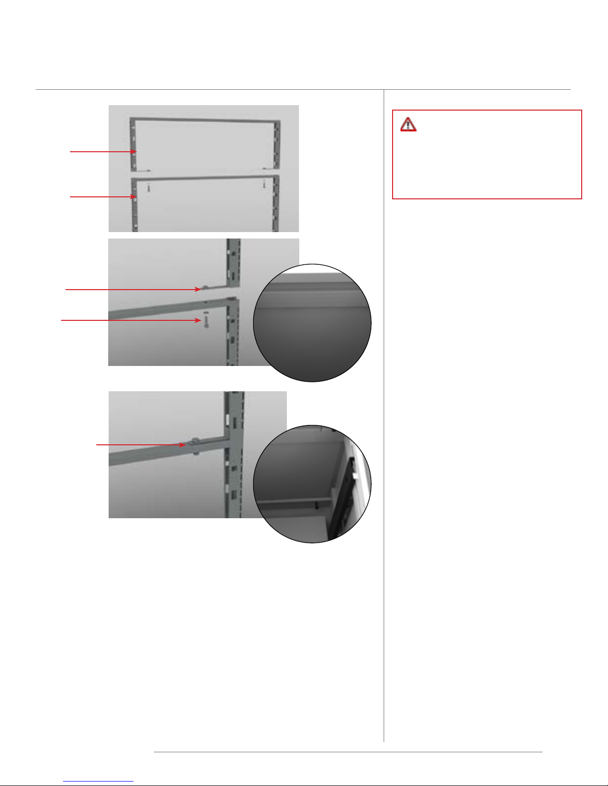
Frame to Frame of Dierent Heights
Taller Frame
Shorter Frame
Use Frame to Frame packages to
connect frames of equal or dierent
heights in a straight line� Frame to
Frame package consists of: a bolt,
alignment nut, and threaded nut�
Use the quantity of Frame to Frame
connection packages needed per the
chart below, and see Frame Connection
Point Location page�
Threaded
Nut
Alignment
Nut
Bolt
Alignment
Nut
Bolt
Threaded
Nut
Correct Assembly
Frame Connection points per height:
Height Connections
29” 2
37” 3
45” 3
53” 3
61” 4
69” 4
Frame to Frame of dierent
height
1� Frames are connected to each other
by means of connecting bolts� A
connecting bolt consists of: a bolt, a
alignment nut and a threaded nut�
2� Bring the shorter frame together
with the taller frame and insert
alignment nut in the hexagonal
cutout at the top of the shorter
frame�
3� Insert threaded nut in the hexagonal
cutout in the taller frame�
Glide
Adjustment
Base cover
holder
Glide
Friant | Interra Installation Manual
4� Insert bolt through the alignment
nut and secure to threaded nut in
the taller frame�
5� Prior to tightening the bolt, insert
the correct number of connecting
bolts for the shorter frame, as per
the table above and at the location
indicated in the Connection Point
Location reference page�
6� After all connecting bolts are
inserted, tighten all bolts until all
stiles come securely together�
7� Do not over tighten�
NOTE: To ensure proper installation
of the product, frames must be
leveled during the installation
process.
9
Stacking Frame Installation
Stacking
Frame
Base
Frame
Securing
Plate
Bolt
WARNING: Never install worksurfaces
on Stacking Frames. Never install
more than one Stacking Frame
on top of a base frame. Overhead
shelves and storage can only be
hung on a Stacking Frame when it
is connected to connectors or other
frames.
1� Remove top tile from base panel at
desired location by pulling towards
you to disengage top clips from
the frame� Pull tile up to disengage
bottom hooks from frame� Repeat
for other side of frame�
2� Remove top cap by removing wing
nuts and lifting top cap� Set aside
for reuse on top of Stacking Frame�
3� Position Stacking Frame above
existing frame, aligning the holes
in brackets with the holes in the
frame� Install two (2) bolts through
the securing plates on the Stacking
Frame� Do not tighten�
Bolt secured
into top of
base frame
4� When installing (2) Stacking Frames
side by side, see Stacking Frame to
Stacking Frame installation on page
11�
5� Tighten bolts into top of base frame�
6� Install top cap on Stacking Frame�
7� Reinstall all tiles�
NOTE: If installing Window Tile
on a Stacking Frame, must specify
Window Tile Stacking.
Friant | Interra Installation Manual
10
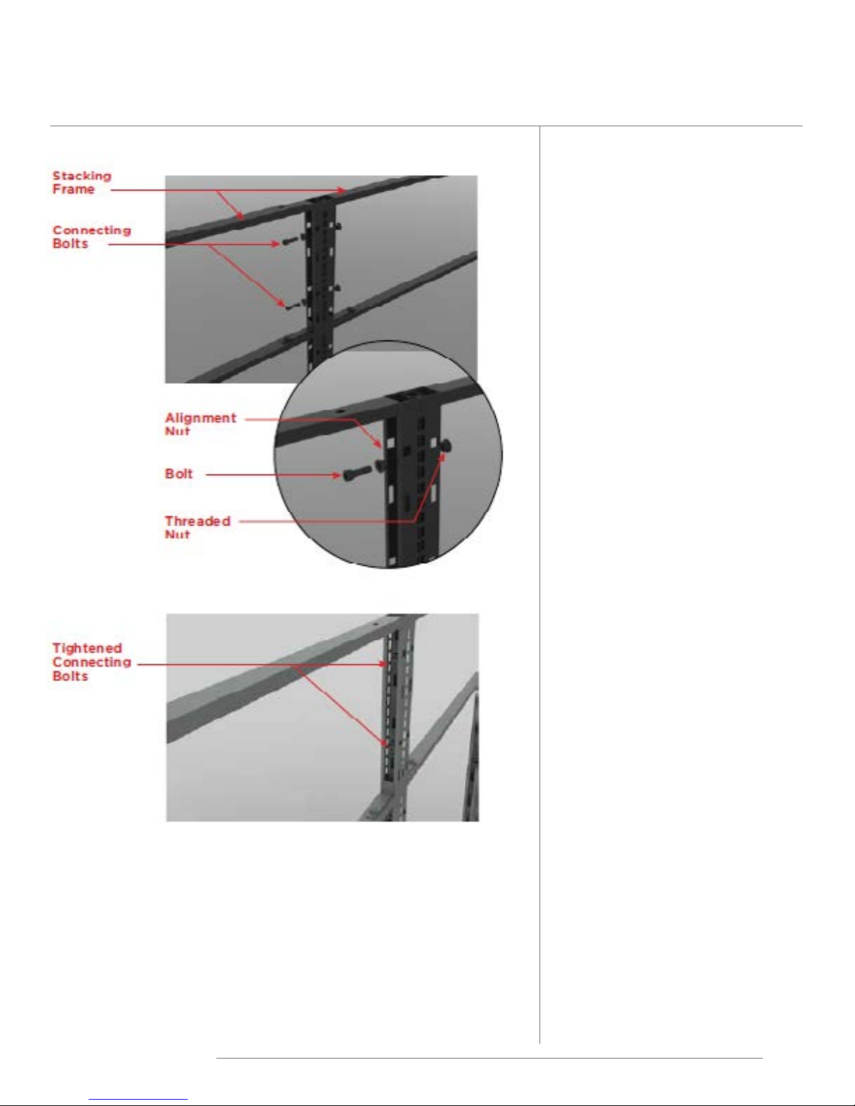
Stacking Frame to Stacking Frame Installation
Frame to Frame of the same
height
1� After securing Stacking Frame
to the base frame (page 8), level
them for attaching together�
2� Stacking Frames are connected
to each other by means of
connecting bolts� A connecting
bolt consists of: a bolt, a
alignment nut and a threaded
nut�
3� Insert alignment nut in the hex-
agonal cutout in frame number 1�
4� Insert threaded nut in the hexag-
onal cutout in frame number 2�
5� Insert bolt through the align-
ment nut and secure to threaded
nut�
6� Prior to tightening the bolt, in-
sert two (2)connecting bolts�
7� After all connecting bolts are
inserted, tighten all bolts until all
stiles come securely together�
8� Do not over tighten�
Friant | Interra Installation Manual
11
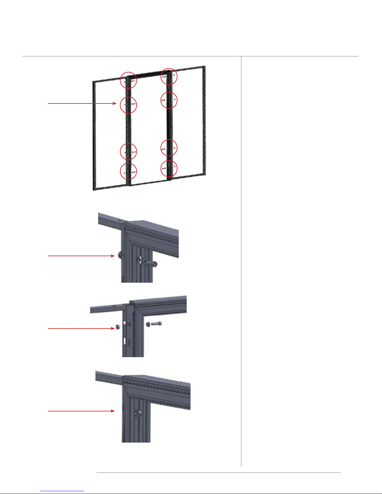
Door Frame Installation
Connecting
Bolts
NOTE: Door swing cannot be
changed. If opposite swing
configuration is needed, a new
door is required.
1� Door Frame is factory
assembled for either left of
right hand swing�
2� Place Door Frame at the
proper location with door
swing on the desired side of
frame�
3� Connect Door Frame
to adjacent frame with
connecting bolts� Each door
frame has a total of eight (8)
bolts, four (4) on each side�
Connecting
Bolt
Connecting
Bolt
Connecting
Bolt
4� Adjust adjacent frame glides
so door opening is square
with the door� Door frame
must be parallel to the flat
face of the door�
Friant | Interra Installation Manual
12
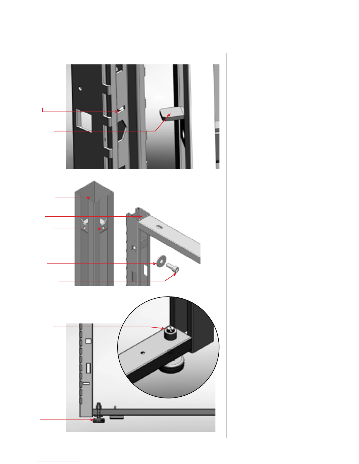
Frame to Connector Assembly
Insertion
Point
Alignment
Tab
Connector
Post
Frame
Frame to Connector
Assembly
Alignment tabs and threaded
inserts are already secured to the
connecting posts�
1� Position frame so that the
alignment tabs at the bottom
of the connector post align with
the corresponding insertion
point on the Frame�
2� Frames are secured to
connector posts by means of
connecting bolts� For frame
to connector assembly, the
connecting bolt consists of a
bolt and a washer as shown in
image to the left� Insert the first
bolt and washer� Tighten bolt
lightly�
Threaded
Insert
Washer
Connecting
Bolt
Glide
Adjustment
Glide
Friant | Interra Installation Manual
3� Continue by inserting the
correct number of connecting
bolts as per the table below,
at the location indicated in the
Connection Point Location
reference page�
4� Prior to tightening all bolts,
ensure that the frame and
connector post are squarely
aligned�
5� Tighten all bolts until stiles and
connector post come securely
together�
See next page for diagram of 2-Way,
3-Way, 4-Way connector post
installation�
Frame Connection points per
height:
Height Connections
29” 2
37” 3
45” 3
53” 3
61” 4
69” 4
85” 5
13
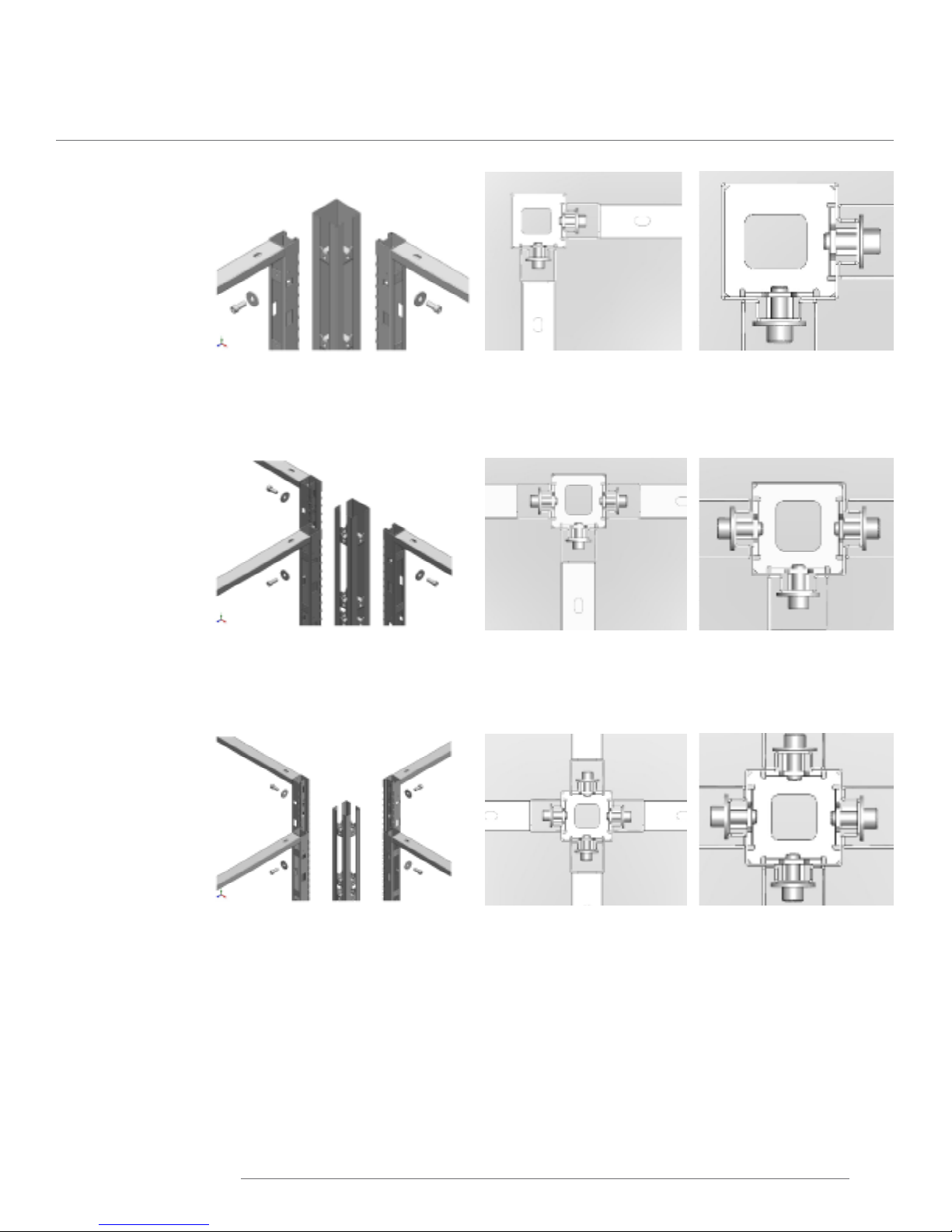
Frame to Connector Assembly: 2-Way, 3-Way, 4-Way
2-Way
3-Way
4-Way
Friant | Interra Installation Manual
14

Stacking Frame to Connector Installation
Stacking Frame to
Connector
1� Stacking Frames are secured to
connector posts by means of
connecting bolts� For Stacking
Frame to connector assembly,
the connecting bolt consists of
a bolt and a washer as shown in
image to the left� Insert the first
bolt and washer� Tighten bolt
lightly�
2� Continue by inserting the
second as shown�
3� Prior to tightening all bolts,
ensure that the frame and
connector post are squarely
aligned�
4� Tighten all bolts until stiles and
connector post come securely
together�
5� Do not over tighten�
Friant | Interra Installation Manual
15
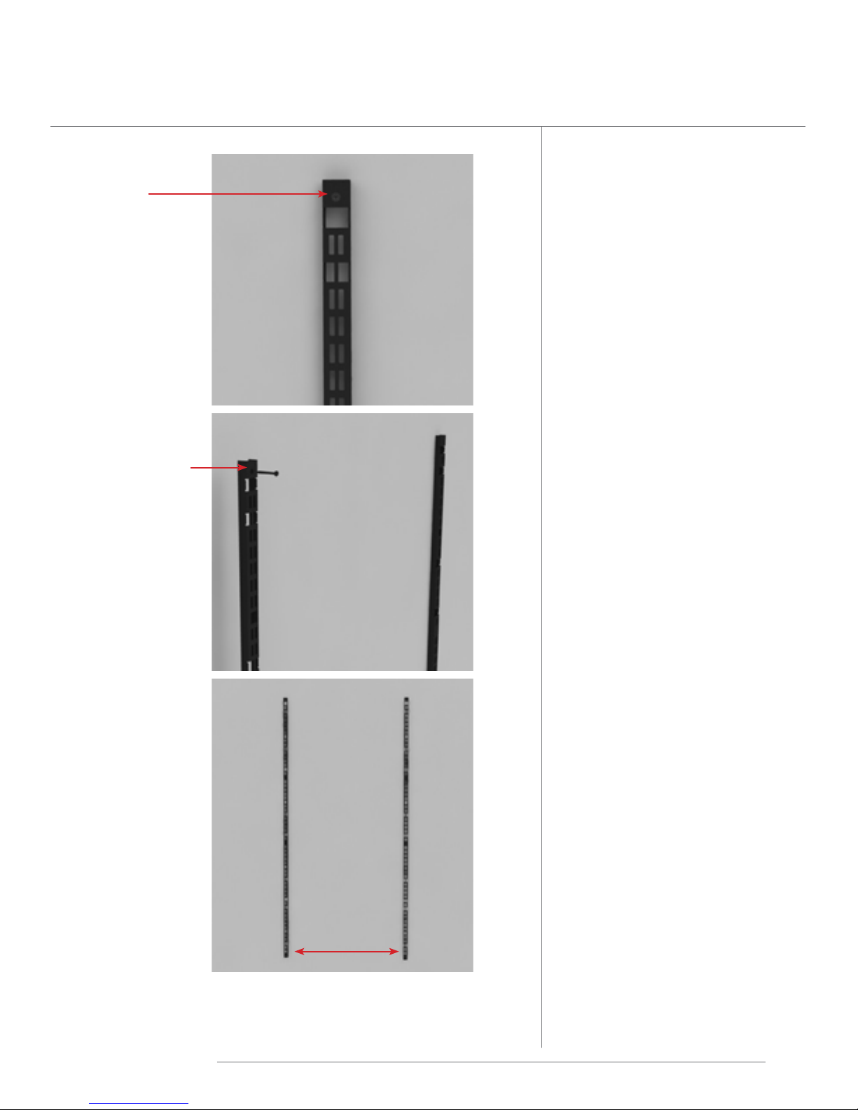
Wall Strip
Wall Strip
secured at
the top hole
NOTE: Wall strips must be installed to
structural walls. Be sure to install wall
strips at studs, if possible.
1� Install the first wall strip,
securing with a screw through
the hole at the top�
2� Ensure that the wall strip is level�
Mark the attachment points on
the wall through the wall strip�
3� Complete attachment to the
wall, by drilling holes at the
attachment points, and securing
with screws�
Second Wall Strip
secured at top
4� Aligning with a level, mark the
location for the second wall
strip� The spacing between wall
strips should be either: 47”, 41”,
35”, 29” or 23”�
5� Repeat steps 2 and 3 to secure
the second wall strip�
distance between
Friant | Interra Installation Manual
Wall Strips
16
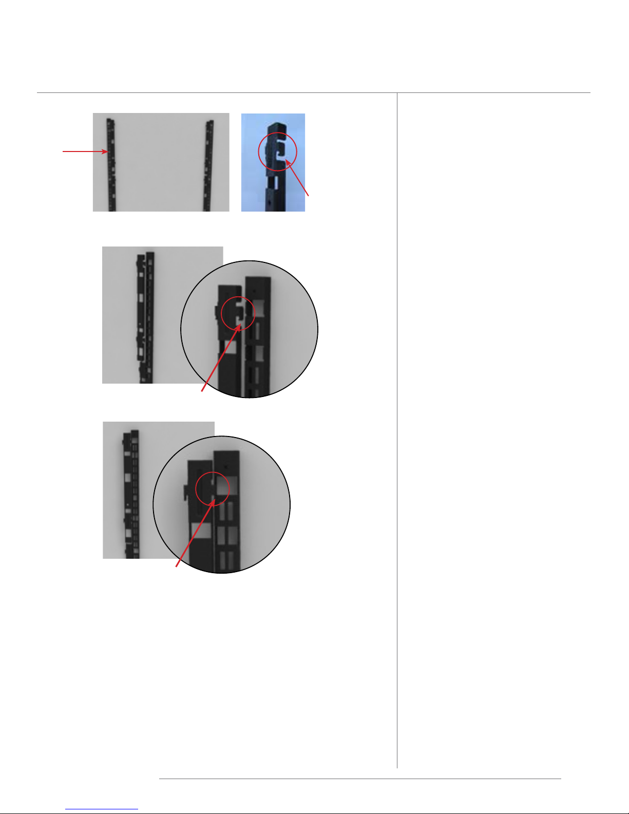
Tile Adapters
Wall
Strips
installed
Inserting Tile Adapter
Tile Adapter hook
Tile Adapter
hook
NOTE: Only available for use with
these tiles: fabric, rail, and perforated
metal.
1� Wall strips should already be
installed�
2� Insert hook of Tile Adapter into
the Wall Strip� Hook should be
oriented as shown in image to
the left�
3� Push Tile adapter to be sure it is
seated securely�
4� For Tile Installation, see pages
45-49�
NOTE: 8” Tile Adapters for use
only at the bottom of a 40” or 56”
wall strip. Not for use in any other
position nor in 64/80” high wall
strips.
Tile Adapter hook
engaged
NOTE: Tile Adapter dimension does
not need to match the tiles installed
(i.e. a 24” tile should be installed on a
32” tile adapter.)
NOTE: When using a 32”H Tile
Adapter, do not use an 8”H tile in the
bottom position.
Friant | Interra Installation Manual
17
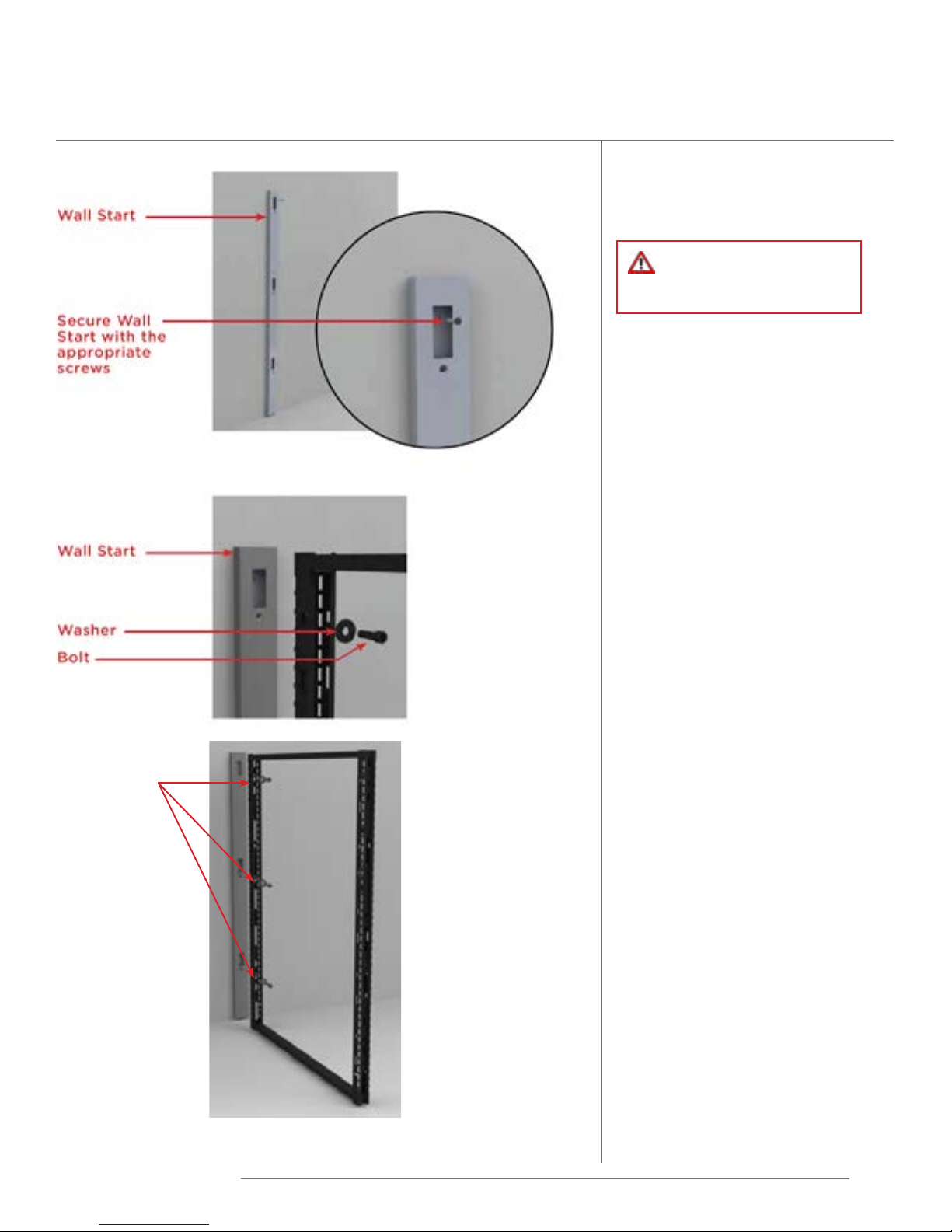
Wall Start
NOTE: Wall Start applications
require some additional tools. Most
important are a good tape measure,
level, drill and appropriate screws for
the type of wall attaching to.
WARNING: The wall
should be reinforced to
prevent damage or injury.
1� Locate on your plan the wall
start� Measure the wall, and
very lightly with a pencil, mark
the location of the wall start�
2� Take a panel and level it to
the wall to determine the
mounting height of the wall
start� Lightly mark the wall at
the top of the panel�
3� Locate the top 2 holes of the
wall start and mark on the
wall for positioning�
Connection
Points
Correct number of bolts
inserted at locations for
this example of a 53”H
frame is 3.
4� Level the wall start and repeat
this step on the middle and
bottom�
5� Secure the wall start to the
wall using the appropriate
screws for the type of wall it
will be attached to�
6� Frames are secured to wall
start by means of connecting
bolts� For frame to wall start
assembly the connecting
bolt consists of a bolt and a
washer as shown in image to
the left�
7� Insert the first bolt and
washer� Tighten bolt lightly�
8� Continue by inserting the
correct number of connecting
bolts at the location indicated
as per the table below, at
the location indicated in the
Connection Point Location
reference page�
Friant | Interra Installation Manual
Frame Connection points per
height:
18
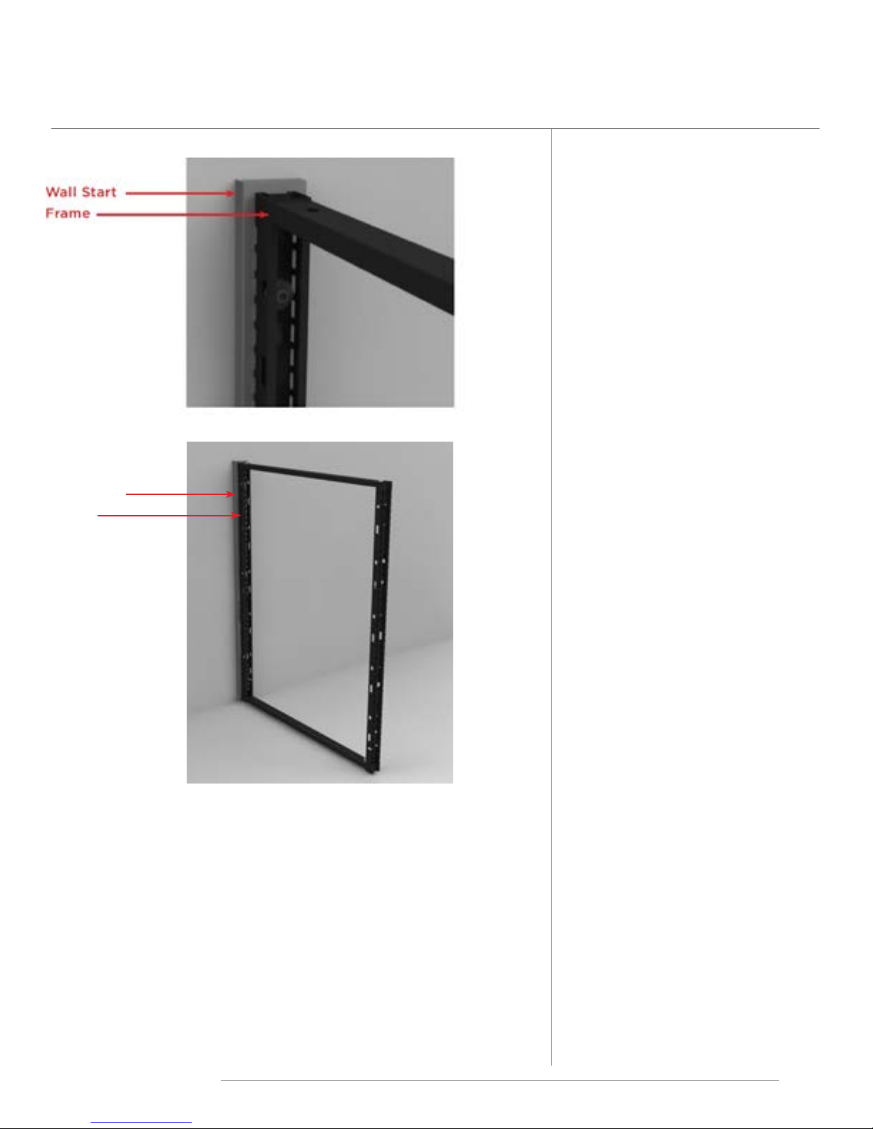
Wall Start
Wall Start
Frame
Height Connections
29” 2
37” 3
45” 3
53” 3
61” 4
69” 4
85” 5
9� Prior to tightening all bolts,
ensure that the frame and wall
start are squarely aligned�
10� Tighten all bolts until stiles
and wall start come securely
together�
11� Do not over tighten�
Friant | Interra Installation Manual
19
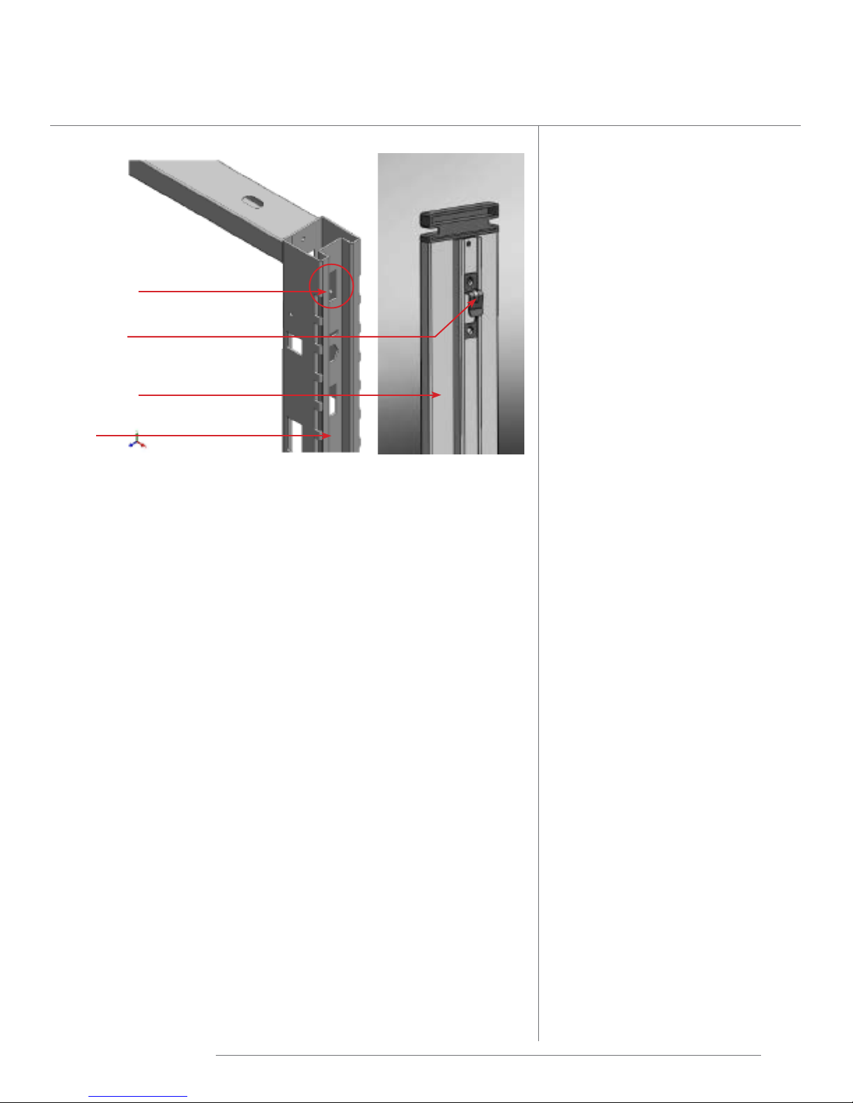
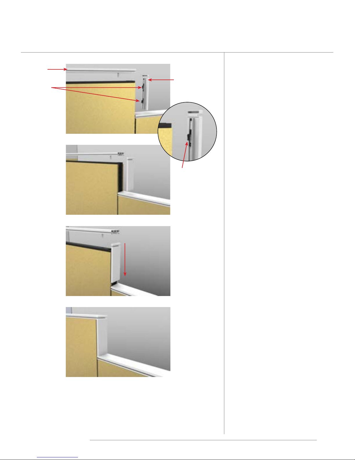
Frame Finished End Installation
Rectangular
Slot
Extended
Tab
Finished
End
Frame Finished End
NOTE: Frame Finished End must
be installed prior to installing the
frame Top Caps.
1� Position the Finished End
onto the frame channel so
the extended tabs at the top
and bottom pass through
the rectangular slots on the
side of the frame�
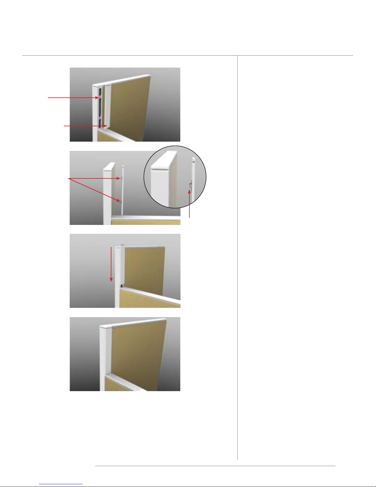
2� Hold the Finished End tight
against the frame and slide
the Finished End down�
Frame
3� To remove Finished End
from the frame, pull the
Finished End up until it
disengages from the frame�
NOTE: After installation of the
Frame Top Cap, should you need to
remove the Finished End, you will
first need to loosen and lift the Top
Cap in order to pull the Finished
End off.
NOTE: If Finished End is loose,
remove Finished End, tighten the
extended tab by pressing down on
it and reinstall.
Friant | Interra Installation Manual
20
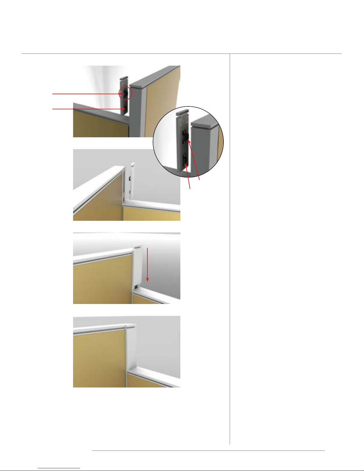
Finished End Change of Height Installation
Finished End Change of
Height for Connectors
Welded
Connection
Plate
Finished End
Change of
Height
Extended Tabs
slide down
to engage
Extended Tab
1� Position the Finished End
Change of Height onto the
connector so the extended
tabs at the top and bottom
pass through the opening
and align with the welded
connection plate�
2� Hold the Finished End
Change of Height tight
against the connector and
slide the Finished End
Change of Height down�
3� To remove Finished End
Change of Height from the
connector, pull the Finished
End Change of Height up
until it disengages from the
connector�
NOTE: If Finished End Change
of Height is loose, remove the
Finished End Change of Height,
tighten the extended tabs by
pressing down on it, and reinstall.
Friant | Interra Installation Manual
21
Finished End Change of Height Installation
Top Cap
Extended
Tabs
Finished End
Change of
Height
Extended Tab
Finished End Change of
Height for Frame to Frame
NOTE: Finished End Change of
Height for Frame to Frame must
be installed prior to installing the
frame Top Caps.
1� Position the Finished End
Change of Height onto
the frame channel so the
extended tabs at the top
and bottom pass through
the rectangular slots on the
side of the frame�
2� Hold the Finished End
Change of Height tight
against the frame and slide
the Finished End Change of
Height down�
3� To remove Finished End
Change of Height from the
frame, pull the Finished End
Change of Height up until it
disengages from the frame�
slide down
to engage
NOTE: After installation of the
Frame Top Cap, should you need to
remove the Finished End, you will
first need to loosen and lift the Top
Cap in order to pull the Finished
End off.
NOTE: If Finished End Change
of Height is loose, remove the
Finished End Change of Height,
tighten the extended tabs by
pressing down on it, and reinstall.
Friant | Interra Installation Manual
22
Finished End Change of Height Installation
Finished End Change of
Height 8”, for Connectors
29”H to 37”H
Magnet
Extended
Tab
Magnet
Extended Tab
1� Position the Finished
2� Hold the Finished End
End Change of Height
onto the connector so
the extended tab at the
bottom passes through the
opening and align with the
welded connection plate,
and magnet holds to the
connector�
Change of Height tight
against the connector and
slide the Finished End
Change of Height down�
slide down
to engage
3� To remove Finished End
Change of Height from the
connector, pull the Finished
End Change of Height up
until it disengages from the
connector�
NOTE: If Finished End Change
of Height is loose, remove the
Finished End Change of Height,
tighten the extended tab by
pressing down on it, and reinstall.
Friant | Interra Installation Manual
23
A/B Base Trim
For use at a 2-Way or
3-Way 90°
When an A-style frame meets a
B-styleframeinaconguration,
an A/B Base Trim is necessary to
cover the exposed frame at the
base. The A/B Base trims snap
into place with little pressure.
FIABBT-2
1� Insert A/B Base Trim inside
connector, long side first�
2� Align u-shaped channel with
edge of connector�
u-shaped
channel
3� Rotate A/B Base Trim
outward until it clicks�
Friant | Interra Installation Manual
24
 Loading...