

Page 1
P/N 70-9008
November 2010
Revision G
Friability T ester
Operator’s Manual
Page 2

Limitation of Liability
The information in this document is subject to change without notice.
Varian, Inc. makes no warranty of any kind with regard to this material,
including, but not limited to, the implied warranties or merchantability
and fitness for a particular purpose. Varian, Inc. shall not be liable for
errors contained herein or for incidental consequential damages in
connection with the furnishing, performance, or use of this material.
All rights are reserved. Reproduction, adaptation, or translation without
prior written permission is prohibited, except as allowed under copyright
laws.
First Edition (November 2010)
Friability Tester Operator’s Manual
Part Number 70-9008 Revision G
Printed in the United States of America
The following terms are trademarks of Varian, Inc.:
• Benchsaver
• BIO-DIS III
• Enhancer Cell
• Full Flow Filters
• Peak Vessel
TM
®
TM
• Practical Solutions
®
TM
• QA and QAII
• TruCenter
• VanKel
• VK
TM
®
®
®
TM
All other trademarks are the property of their respective owners.
Varian, Inc.
13000 Weston Parkway
Cary, North Carolina 27513-2250
800.229.1108
919.677.1108
Fax: 919.677.1138
www.varianinc.com
Copyright (c) 1999 - 2010 by Varian, Inc.
Page 3

T a ble of Contents
Chapter 1 Safety Practices and Hazards 7
Electrical Hazards 8
Other 8
General 10
WEEE Directive 11
Chapter 2 Introduction 13
Available Configurations 15
Conventions Used in this Manual 16
Varian, Inc.
Page 4

Table of Contents
Chapter 3 Installation and Setup 17
Unpacking Your Equipment 17
Connecting the Report Center Printer 18
Setting the Date and Time 19
Hidden Key Functions 20
Chapter 4 Operation 21
Operating the Friability Tester without a Printer 21
Running a Test 21
Stopping a Test 23
Operating the Friability Tester with a Printer 24
Configuring for the Number of Chambers or Drums Used 24
Running a Test 25
Stopping a Test 28
Chapter 5 Maintenance and Troubleshooting 29
Maintenance 29
Periodic Maintenance 29
Acrylic Care 30
Report Center Impact Printer 31
Installing the Cartridge Ribbon 31
Replacing the Paper Roll 32
Toggling Your Printer Online 34
Printer Self Test 34
Printer Configuration 35
Fuse Replacement 37
Troubleshooting 38
Varian, Inc.
Page 5

Table of Contents
Chapter 6 Service and Warranty 39
Exclusions and Limitations 40
Obtaining Warranty Service 40
Warranty Limitations 40
Exclusive Remedies 41
Index 43
Tell Us How We Are Doing 45
Varian, Inc.
Page 6

Table of Contents
This page was intentionally left blank, except for this message.
Varian, Inc.
Page 7

Chapter 1 Safety Practices
and Hazards
The Friability Tester has been carefully designed so that when used properly you have an
accurate, fast, flexible, and safe instrument.
If the equipment is used in a manner not specified by the manufacturer, the protection
provided by the equipment may be impaired.
Operation of a Friability Tester involves the use of solid dosage forms. Unskilled,
improper, or careless use of this instrument can create shock hazards, fire hazards, or
other hazards which can cause death, serious injury to personnel, or severe damage to
equipment and property.
Information on safety practices is provided with your instrument and operation manuals.
Before using your instrument or accessories, you must thoroughly read these safety
practices.
Observe all relevant safety practices at all times.
Varian, Inc.
Page 8

Page 8 Friability Tester Revision G, 11/10
Safety Practices and Hazards Operator’s Manual P/N 70-9008
Electrical Hazards
The Friability Tester contains electrical circuits, devices, and components operating at
dangerous voltages. Contact with these circuit s, de vices, and component s ca n cause
death, serious injury, or painful electric shock.
Panels or covers that are retained by fasteners which require the use of a tool for
removal may be opened only by Varian-trained, Varian-qualified, or Varian-authorized
service engineers. Consult the manuals or product labels supplied with the Friability
Tester to determine which parts are operator-accessible.
Application of the wrong supply voltage, connection of the instrument to an incorrectly
wired supply outlet, or lack of proper electrical grounding can create a fire hazard or a
potentially serious shock hazard and could seriously damage the instrument and any
attached ancillary equipment.
Always use a three-wire outlet with ground connection which is adequately rated for
the load. The installation must comply with local, state, and federal safety regulations.
Do not connect the instrument to the main power supply until you have made sure
that the operating voltage is correctly set for the main power supply in the specific
outlet in your laboratory to which the equipment will be connected.
Other
Other specific warnings and cautions appear in the manuals where appropriate and
detail the specific hazard, describe how to avoid it, and specify the possible
consequences of not heeding the warning or caution.
Warning
A ‘Warning’ message appears in the manual when failure to observe instructions or
precautions could result in death or injury . Symbols dep icting the nature of the specific
hazard are also placed alongside warnings.
Varian, Inc.
Page 9
Revision G, 11/10 Friability Tester Page 9
P/N 70-9008 Operator’s Manual Safety Practices and Hazards
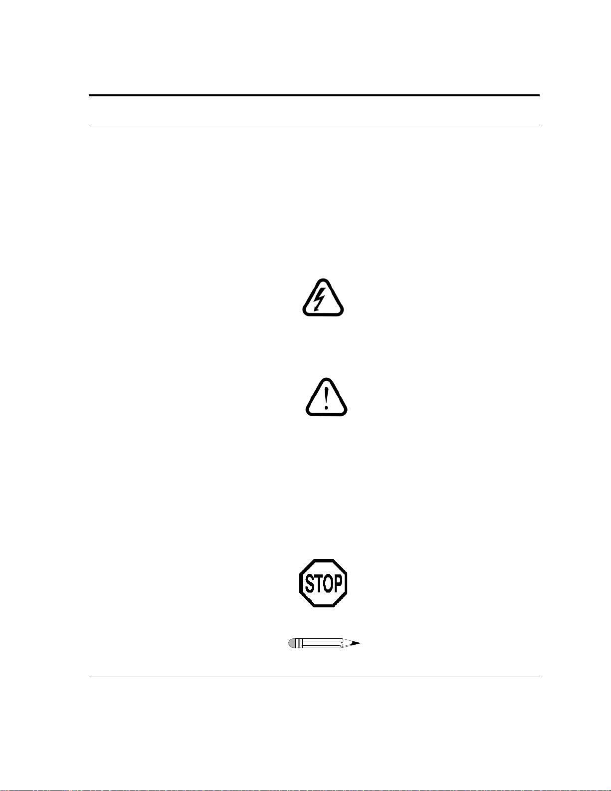
These symbols may be used on warning labels attached to the instrument. When you see
one of these symbols you must refer to the relevant operation or service manual for the
correct procedure referred to by that warning label.
The meaning of the symbols that appear alongside warnings in this manual are as
follows:
Electrical shock
Caution
Refer to accompanying documents
Read all warnings and cautions carefully and observe them at all times.
Caution
A ‘Caution’ message appears in the manual when failure to observe instructions could
result in damage to equipment (Varian supplied and / or other associated equipment).
A ‘Note’ appears in the manual to give advice or information.
Varian, Inc.
Page 10
Page 10 Friability Tester Revision G, 11/10
Safety Practices and Hazards Operator’s Manual P/N 70-9008
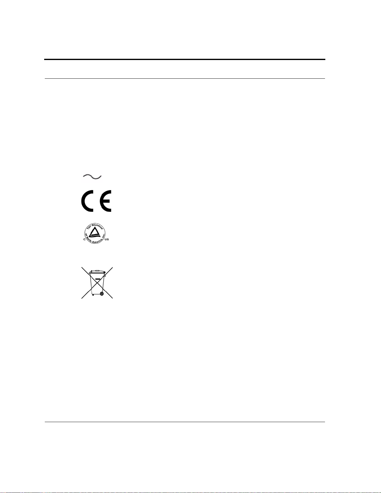
Information symbols
Switches main power on
I
Switches main power off
0
Indicates single-phase alternating current
Indicates the product complies with the requirements of one
or more European Union (EU) directives
Indicates specific equipment meets consensus-based
standards of safety to provide assurance, required by
OSHA, that these products are safe for use in the workplace
for North America
Indicates that this product must not be disposed of as
unsorted municipal waste (see “WEEE Directive” on
page 11)
General
CE Compliant Products
The Friability Tester has been designed to comply with the requirements of the
Electro-magnetic Compatibility (EMC) Directive and the Low Voltage Directive (LVD)
of the EU.
Varian, Inc. has confirmed that each product complies with the relevant directives by
testing a prototype against the prescribed European Norm (EN) standards.
Varian, Inc.
Page 11

Revision G, 11/10 Friability Tester Page 11
P/N 70-9008 Operator’s Manual Safety Practices and Hazards
Proof that a product complies with the directives is indicated by:
• the CE marking appearing on the rear of the product.
• the documentation package that accompanies the product containing a copy of
the declaration of conformity. This declaration is the legal declaration by Varian,
Inc. that the product complies with the directives and also shows the EN standards
to which the product was tested to demonstrate compliance. The declaration of
conformity is signed by the representative of the manufacturing plant.
cTUVus - U.S. and Canadian Product Approvals
The Friability Tester has been designed to comply with North American safety
requirements.
This product has been tested and certified for the North American market by TUV
Rheinland of North America, Inc. The TUVus mark signifies that this product has been
tested to U.S. standards and certified for the U.S. market. The cTUV mark signifies that
this product has been tested to Canadian standards and certified for the Canadian
market. When the two marks are coupled, the cTUVus mark signifies that this product has
been tested to standards and certified for both markets.
WEEE Directive
All Varian products that are subject to the WEEE directive shipped after August 13, 2005
are compliant with the WEEE marking requirements. Such products are marked with the
“crossed out wheelie bin” WEEE symbol shown on page 10 in accordance with European
Standard EN 50419.
This symbol on the product or on its packaging indicates that this product must not be
disposed of as unsorted municipal waste. The separate collection and recycling of your
waste equipment at the time of disposal will help to conserve natural resources and
ensure that it is recycled in a manner that protects human health and the environment.
For more information on collection, reuse, and recycling systems, please contact your
local/regional waste administration, your local distributor, or Varian, Inc.
Varian, Inc.
Page 12

Page 12 Friability Tester Revision G, 11/10
Safety Practices and Hazards Operator’s Manual P/N 70-9008
This page was intentionally left blank, except for this message.
Varian, Inc.
Page 13
Chapter 2 Introduction
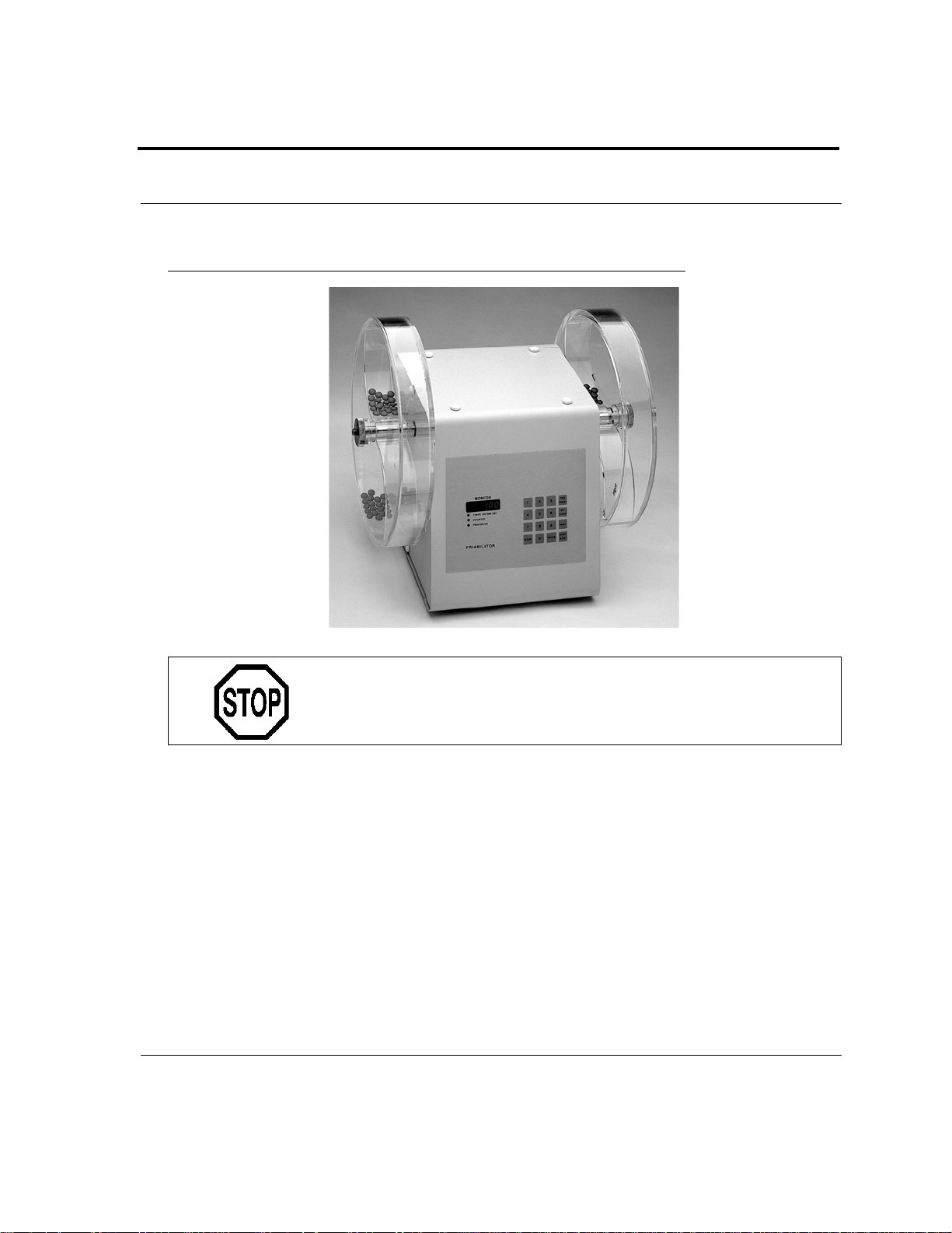
Your Friability Tester provides a standardized, reproducible method for measuring the
tendency of a tablet or its coating to chip or powder when subjected to the mechanical
stresses of the coating as well as the shipping and handling processes. The Friability
Tester drums turn at a constant 25 RPM with precision and accuracy ensured by the use
of a synchronous motor. Speed is linked to the AC line frequency, usually either 50 or 60
Hz, depending on your geographic location. As the product in the drum tumbles against
the drum’s internal vane, its loss due to breakage or chipping can be measured. The
Friability Tester is available in a single-drum and dual-drum model.
An optional Report Center Printer provides documentation of instrument operation
including test start time, operating mode, and set du ration in either number of rot ations or
elapsed time. On units equipped with the Report Center Printer, you can enter the starting
and ending weights of the tablets and the percentage loss is calculated per USP.
Warning
The Friability Tester contains electrical circuits, devices, and
components operating at dangerous voltages. Contact with these
circuits, devices, and components can cause death, serious
injury, or painful electric shock.
Varian, Inc.
Page 14
Page 14 Friability Tester Revision G, 11/10
Introduction Operator’s Manual P/N 70-9008
FIGURE 1. Dual-drum Friability Tester
Caution
Panels or covers that are retained by fasteners which require the
use of a tool for removal may be opened only by Varian-trained,
Varian-qualified, or Varian-authorized service engineers.
Varian, Inc.
Page 15

Revision G, 11/10 Friability Tester Page 15
P/N 70-9008 Operator’s Manual Introduction
Available Configurations
The Friability Tester is available in a single-drum or dual-drum configuration. The
dual-drum configuration turns synchronously on opposite ends of the same shaft. This
option allows two tests to run simultaneously.
Three types of drums are available:
• Traditional Roche-type USP drum with a single-chamber design.
• Varian USP drum with two arched bridges which saves time by allowing for two
tests in one drum.
• Abrasion drum with internal baffles to agitate the product inside—for applications
requiring a high degree of mechanical stress.
Varian, Inc.
Page 16

Page 16 Friability Tester Revision G, 11/10
Introduction Operator’s Manual P/N 70-9008
Contact the Dissolution Systems Service Department for any special drum needs you
may have.
Conventions Used in this Manual
• Items you are asked to press are in bold. For example, “press START STOP on
the keypad” or “Press ENTER”.
• Key sequences you are asked to press appear like this: CLEAR > 1.
Note
Remember to return the warranty card supplied with this manual.
Completing and returning the card ensures your right to
protection under the terms and conditions of your warranty. It
also enables us to better assist you in the event of any problems.
Additionally, it guarantees you will be informed of any iss ues that
arise concerning your equipment, such as upgrades, retrofits, or
regulatory changes.
Varian, Inc.
Page 17
Chapter 3 Installation
and Setup
Unpacking Your Equipment
Complete these steps to safely unpack and set up your equipment:
Step 1. Open each carton and check the contents for damage which may have
occurred during shipping. Shipping damage rarely occurs, but if it does
contact both the carrier who delivered the instruments and the
Dissolution Systems Service Department. Though claims for damage
should be filed with the carrier, we can help you file a claim.
Step 2. Carefully remove the Friability Tester base unit from the shipping carton.
Place it on a clean, dry, level area of your benchtop within four feet
(122 cm) of a grounded electrical outlet.
Warning
The electrical connection at the back of the tester is the primary
disconnect for the instrument. The tester should be positioned to
allow accessibility to the power cords for easy disconnection.
Step 3. Ensure the Friability Tester is turned off.
Varian, Inc.
Page 18
Page 18 Friability Tester Revision G, 11/10
Installation and Setup Operator’s Manual P/N 70-9008
Warning
Before plugging the Friability T e ster into any power outlet, en sure
the instrument is properly configured for the voltage provided.
Check the serial number tag on the rea r panel of th e instrument to
confirm the voltage requirement.
Step 4. Connect the power cord (found in the instrument accessory kit) between
the receptacle on the rear panel and an electrical outlet of the
appropriate voltage.
Step 5. Turn on the Friability Tester. The LED screen on the front panel
illuminates. If not, ensure the unit is securely plugged in and there is
power at the outlet. If the unit still fails to respond, see “Troubleshoot ing”
on page 38 or call the Dissolution Systems Service Department.
Connecting the Report Center Printer
If your tester is equipped with the optional Report Center Printer, complete the following
steps:
Step 1. Remove the printer from the shipping carton.
Step 2. Place it on a clean, dry, level area of your benchtop to the right of your
Friability Tester.
Step 3. Connect the printer cable between the rear of the printer and the port on
the right side panel of the Friability Tester.
Step 4. Connect the AC power adapter between the jack on the rear of the
printer and an electrical outlet of the appropriate voltage.
Step 5. Toggle the printer online by pressing the printer toggle switch to the
OnLine / Off Line position. The Ready LED illuminates. If not, ensure the
printer is securely plugged in and there is power at the outlet. If the
device still fails to respond, see “T roubleshooting ” on page 38 or call the
Dissolution Systems Service Department.
Varian, Inc.
Page 19

Revision G, 11/10 Friability Tester Page 19
P/N 70-9008 Operator’s Manual Installation and Setup
Setting the Date and Time
The Friability Tester comes equipped with a battery-backed up clock which stores the
date and time. If your unit is equipped with the Report Center Printer, the date and
starting time print on the report. If applicable, complete the following step s to se t the date
and time:
Step 1. Press SET CLOCK. The current date (in mm/dd/yy format) and time (in
24-hour format) display alternately.
Step 2. To accept the current date and time, press CLEAR. The test duration
displays and no further action is required.
To change the date and time, press SET CLOCK again. The date
displays in mm/dd/yy format.
Step 3. To accept the date as it displays, press ENTER. The time displays in
24-hour format.
To change the date, enter the new value and press ENTER. The time
displays in 24-hour format.
Step 4. To accept the time as it displays, press ENTER. The test duration
displays.
To change the time, enter the new value and press ENTER. The test
duration displays.
Varian, Inc.
Page 20

Page 20 Friability Tester Revision G, 11/10
Installation and Setup Operator’s Manual P/N 70-9008
Hidden Key Functions
Hidden keys can be accessed only when the Printer On LED is not illuminated, indicatin g
that the printer is disabled, and the motor is running. Press PRINT to enable or disable
the printer. To enable the PRINT key, press CLEAR > 9. In the following table, CLEAR >
(function) indicates you should press CLEAR and then the function key.
Key
Sequence Function
CLEAR > 1 Use this key sequence to indicate one chamber.
CLEAR > 2 Use this key sequence to indicate two chambers.
CLEAR > 3 Use this key sequence to indicate three chambers.
CLEAR > 4 Use this key sequence to indicate four chambers.
CLEAR > 6 Use this key sequence to enable the PCB display.
CLEAR > 8 Use this key sequence to indicate the Friability Tester.
CLEAR > 9 Use this key sequence to enable the PRINT key.
CLEAR > 0 Use this key sequence to disable PRINT key.
Varian, Inc.
Page 21

Chapter 4 Operation
Operating the Friability Tester without a Printer
If your unit is equipped with a Report Center Printer, see “Operating the Friability Tester
with a Printer” on page 24.
Running a Test
Complete the following steps to run a test using a Friability Tester not equipped with a
Report Center Printer:
Step 1. Ensure the PRINT key is disabled. See “Hidden Key Functions” on
page 20 for instructions on how to disable the PRINT key.
Step 2. Select the mode of operation, either timer or counter, by pressing
TIME COUNT. This key toggles the unit between the two operating
modes. The Timer LED illuminates to indicate the timer option is
selected. The Counter LED illuminates to indicate the counter option is
selected.
Varian, Inc.
Page 22
Page 22 Friability Tester Revision G, 11/10
Operation Operator’s Manual P/N 70-9008
Step 3. Enter either the number of rotations (up to 999,999) or the time
duration (in hh:mm:ss format) as applicable and press ENTER. Once
entered, the test duration is saved by the unit and does not need to be
reset unless you want to change it. To change the duration, enter the
new value and press ENTER.
Step 4. Locate the drums supplied with your unit. Hold the drums firmly so the
covers do not fall off. Place the drums on the benchtop and carefully
remove the covers and set them aside.
Note
The right- and left-side drums are not interchangeable. The vanes
curve in opposite directions. Be sure to identify them properly
before mounting. Drums supplied with dual-drum units have
right- and left-side co nfigurations. Check the lab el on the cover of
each to identify them. Left-side drums mount on the left side of
the unit as viewed from the front. Right-side drums mount on the
right side as viewed from the front.
Step 5. Brush away any loose dust from the tablets to be tested.
Note
Follow USP guidelines or applicable test procedures to determine
the number of tablets to be tested. Generally, a minimum of 20
tablet s should be used in testing. For tablets weighing over
650 mg each, 10 tablets are usually sufficient.
Step 6. Accurately weigh the tablets.
Step 7. Load the tablets to be tested into the drums and replace the covers.
Step 8. For each drum, hold the cover firmly in place and slide the drum body
onto the shaft. There are two pins at the end of the shaft which hold
the drum while the shaft turns. Match the pins with the slots in the hub.
Step 9. For each drum, place the locking nut on the end of the shaft and
tighten. Do not overtighten or damage to the drum may result.
Varian, Inc.
Page 23

Revision G, 11/10 Friability Tester Page 23
P/N 70-9008 Operator’s Manual Operation
Step 10. Press START STOP to begin. The time duration or number of rotations
count down on the display screen and the test stops automatically when
0 is reached. The display automatically resets to the original set value
preparing the instrument for the next test.
Step 11. At the conclusion of the test, remove the drums.
Step 12. Remove the tablets and brush away any loose dust. Per the USP, if
obviously cracked, cleaved, or broken tablets are present in the tablet
sample after tumbling, the sample fails the test.
Step 13. Re-weigh the tablets. Calculate the percentage of weight loss using the
following formula:
% weight loss = initial weight - final weight
x 100%
initial weight
Stopping a Test
When running a test on a Friability Tester without a printer, you can stop the test by
pressing START STOP. The drums stop immediately and the display returns to the
original test length setting.
Varian, Inc.
Page 24

Page 24 Friability Tester Revision G, 11/10
Operation Operator’s Manual P/N 70-9008
Operating the Friability T ester with a Printer
If your unit is not equipped with a Report Center Printer, see “Operating the Friability
Tester without a Printer” on page 21.
Configuring for the Number of Chambers or Drums
Used
Complete the following steps to configure your printer-equipped Friability Tester for the
number of chambers or drums in use:
Step 1. Ensure the Printer On LED is not illuminated. If the LED is illuminated,
press PRINT to disable the printer.
Step 2. Press START STOP. The drums rotate.
Step 3. Press the following keystroke combinations depending on the number
of chambers you wish to specify:
• CLEAR > 1 - one chamber
• CLEAR > 2 - two chambers
• CLEAR > 3 - three chambers
• CLEAR > 4 - four chambers
Step 4. Press START STOP. The drums stop rotating.
Step 5. Press PRINT to enable the printer. The Printer On LED illuminates.
The next time you press START STOP, with the printer enabled, the
appropriate number of initial and final weights are requested based on
the number of chambers specified.
Varian, Inc.
Page 25

Revision G, 11/10 Friability Tester Page 25
P/N 70-9008 Operator’s Manual Operation
Running a Test
If your unit is equipped with the optional Report Center Printer, you can print a report at
the end of each test to document the date, starting time, mode selected, and the set
duration. If the Printer On LED is illuminated, the printer is enabled. Press PRINT to
enable or disable the printer.
Complete the following steps to operate your Friability Tester with Report Center Printer:
Step 1. Ensure the printer is enabled. When enabled, the Printer On LED
illuminates.
Step 2. Toggle the printer online by pressing the printer toggle switch to the
OnLine / Off Line position. The Ready LED illuminates.
Step 3. Select the mode of operation, either timer or counter, by pressing
TIME COUNT. This key toggles the unit between the two operating
modes. The Timer LED illuminates to indicate the timer option is
selected. The Counter LED illuminates to indicate the counter option is
selected.
Step 4. Enter either the number of rotations (up to 999,999) or the time duration
(in hh:mm:ss format) as applicable and press ENTER. Once entered, the
test duration is saved by the unit and does not need to be reset unless
you want to change it. To change the duration, enter the new value and
press ENTER.
Varian, Inc.
Page 26
Page 26 Friability Tester Revision G, 11/10
Operation Operator’s Manual P/N 70-9008
Step 5. Locate the drums supplied with your unit. Hold the drums firmly so the
covers do not fall off. Place the drums on the benchtop and carefully
remove the covers and set them aside.
Note
The right- and left-side drums are not interchange able. The vanes
curve in opposite directions. Be sure to identify them prop e r ly
before mounting. Drums supplied with dual-drum units have
right- and left-side configura tions. Check the label on t he cover of
each to identify them. Left-side drums mount on the left side of
the unit as viewed from the front. Right-side drums mount on the
right side as viewed from the front.
Step 6. Brush away any loose dust from the tablets to be tested.
Note
Follow USP guidelines or applicable test procedures to determine
the number of tablets to be tested. Generally, a minimum of 20
tablet s should be used in testing. For tablets weighing over
650 mg each, 10 tablets are usually sufficient.
Step 7. Accurately weigh the tablets.
Step 8. Load the tablets to be tested into the drums and replace the covers.
Step 9. For each drum, hold the cover firmly in place and slide the drum body
onto the shaft. There are two pins at the end of the shaft which hold
the drum while the shaft turns. Match the pins with the slots in the hub.
Step 10. For each drum, place the locking nut on the end of the shaft and
tighten. Do not overtighten or damage to the drum may result.
Varian, Inc.
Page 27

Revision G, 11/10 Friability Tester Page 27
P/N 70-9008 Operator’s Manual Operation
Step 11. Press START STOP. You are prompted to enter the initial weight (in
grams) of the product in the drum. Up to four weights can be entered
depending on the number of chambers or drums used (see “Co nfig uring
for the Number of Chambers or Drums Used” on p age 24). The following
is a summary of what displays after pressing START STOP but before
the drums begin to turn:
• The number 1 displays on the display screen alternating with the last
initial weight entered for the product in chamber or drum 1. Press
ENTER to accept the displayed value or enter the new initial weight and
press ENTER. If configured for one chamber or drum, the drum begins
to turn.
• If configured for two chambers or drums, the number 2 flashes on the
display screen alternating with the last initial weight entered for the
product in chamber or drum 2. Press ENTER to accept the displayed
value or enter the new initial weight and press ENTER. If configured for
two chambers or drums, the drums begin to turn.
• If configured for three chambers, the number 3 flashes on the display
screen alternating with the last initial weight entered for the product in
chamber 3. Press ENTER to accept the displayed value or enter the
new initial weight and press ENTER. If configured for three chambers,
the drums begin to turn.
• If configured for four chambers, the number 4 flashes on the display
screen alternating with the last initial weight entered for the product in
chamber 4. Press ENTER to accept the displayed value or enter the
new initial weight and press ENTER. If configured for four chambers,
the drums begin to turn.
Note
When the drums have stopped turning at the conclusion of the
test, the screen prompts you to enter ending weights for the
products in each chamber or drum as it did for starting weights.
Step 12. At the conclusion of the test, remove the drums.
Varian, Inc.
Page 28

Page 28 Friability Tester Revision G, 11/10
Operation Operator’s Manual P/N 70-9008
Step 13. Remove the tablets and brush away any loose dust. Per the USP, if
obviously cracked, cleaved, or broken tablets are present in the tablet
sample after tumbling, the sample fails the test.
Step 14. Re-weigh the tablets and enter the requested values.
Step 15. After the ending weight for the last chamber or drum has been
entered, the Report Center prints a test report includin g the ca lculated
percentage of weight loss for all samples.
Stopping a Test
Step 1. When running a test on a Friability Tester equipped with a printer, you
can stop the test by pressing START STOP. The drums stop
immediately and the display prompts you to enter the ending weights
for the products as described above.
Step 2. Enter the ending weights and press ENTER for each chamber as
applicable. The printer prints a test report and calculates the
percentage of weight loss for the products even though the test was
stopped prematurely.
Varian, Inc.
Page 29
Chapter 5 Maintenance and
Troubleshooting
Maintenance
Warning
The Friability Tester contains electrical circuits, devices, and
components operating at dangerous voltages. Contact with these
circuits, devices, and components can cause death, serious
injury, or painful electric shock.
Periodic Maintenance
Periodic maintenance needs may vary depending on frequency of instrument usage.
• Immediately wipe all spills or errant materials from the exterior of the instrument or
any exposed part using a clean cloth and plain water.
• Do not use cleaners containing ammonia or organic solvents, such as alcohol, on
the acrylic drums. These compounds can attack the plastic, causing cracks and
fractures which will not be covered by the warranty.
• Store all Friability Tester drums properly.
Varian, Inc.
Page 30
Page 30 Friability Tester Revision G, 11/10
Maintenance and Troubleshooting Operator’s Manual P/N 70-9008
Monthly Maintenance
• Check the drums for cracks or chips.
• Wipe the shaft clean.
• Ensure the pins which hold the drums while the shaft turns are not bent.
• Clean the outside of the tester with a damp cloth.
Annual Maintenance
Warning
The Friability Tester contains electrical circuits, devices, and
components operating at dangerous voltages. Contac t with these
circuits, devices, and components can cause death, serious
injury, or painful electric shock.
Panels or covers that are retained by fasteners which require the
use of a tool for removal may be opened only by Varian-trained,
Varian-qualified, or Varian-authorized service engineers.
• Inspect all electrical connections for corrosion and damage.
• Clean the inside and outside of the tester with a damp cloth.
• Check belt tension—total deflection should not exceed 1/2 inch (1.3 cm).
Acrylic Care
Caution
Do not use cleaning compounds cont ain ing ammon ia or abra sive
cleaners on your drums.
1. the Friability Tester drums are fabricated of commercial grade acrylic. Be sure to rinse
them thoroughly with deionized water after each use, and dry thoroughly with a soft
towel or cloth.
2. Do not clean with abrasive cleansers or cloths. Use deionized water whenever
possible. If you must use a cleanser or solvent, be sure that it is as mild as possible,
Varian, Inc.
Page 31

Revision G, 11/10 Friability Tester Page 31
P/N 70-9008 Operator’s Manual Maintenance and Troubleshooting
non-abrasive, and fully compatible with PETG and acrylic before use. If in doubt, call
the service department for advice before proceeding.
3. Do not use ammonia, window-cleaning sprays, kitchen scouring compounds, or
solvents such as acetone, gasoline, benzene, alcohol, carbon tetrachloride, or lacquer
thinner. These can scratch the material’s surface and / or weaken it causing small
surface cracks called “crazing”.
4. Our recommendations include but are not limited to the following:
• Hot water:< 150 °F
• Vinegar (5% Glacial Acetic Acid)
• Ethyl alcohol: maximum 10%
• Isopropyl alcohol: maximum 25%
Report Center Impact Printer
The following is helpful information for using your impact printer.
Installing the Cartridge Ribbon
If the printer is used infrequently, the print impression sometimes becomes weak because
the ribbon dries out. If the printed material is difficult to read and you suspect this is the
cause of the problem, advance to a new section of the ribbon by pressing the printer
toggle switch to the Paper feed position. If the printing is still faint, replace the cartridge.
To install the cartridge:
Step 1. Toggle the printer off line by pressing the printer toggle switch to the
OnLine / Off Line position. When the printer is off line, the Ready LED
does not illuminate.
Step 2. Four small grooves are embossed on the printer cover. Gently push on
these grooves to tilt the cover. When the printer cover is tilted up, you
can lift it off completely.
Varian, Inc.
Page 32

Page 32 Friability Tester Revision G, 11/10
Maintenance and Troubleshooting Operator’s Manual P/N 70-9008
Step 3. Push down on the right side of the ribbon cartridge (marked PUSH) and
remove the old cartridge.
Step 4. Install the new cartridge. If there is already paper in the printer, hold the
cartridge between your thumb and index finger, slide it over the paper
and into the printer compartment. Ensure the paper is between the
ribbon cartridge and the ink ribbon. Ensure the ribbon cartridge is
inserted firmly to prevent weak or irregular printing. The cartridge must
be properly seated and aligned for the best printing.
Step 5. Turn the cartridge knob (marked by an arrow) clockwise to stretch the
ribbon taut.
Step 6. Replace the cover.
Step 7. Toggle the printer online by pressing the printer toggle switch to the
OnLine / Off Line position. The Ready LED illuminates.
Step 8. Replace the paper if necessary.
If you get ribbon ink on the printer’s plastic cover, remove it immediately. Once dried, it is
difficult to remove.
Replacing the Paper Roll
Step 1. Toggle the printer off line by pressing the printer toggle switch to the
OnLine / Off Line position. When the printer is off line, the Ready LED
does not illuminate.
Step 2. Grasp the paper roll cover firmly by the grooves on the side and the front
edge. Pull outward to remove the cover.
Step 3. Press the printer toggle switch to Paper feed to advance the paper
approximately one inch beyond the paper cutter.
Step 4. Using scissors, cut the paper feeding to the printer and remove the
paper roll.
Varian, Inc.
Page 33
Revision G, 11/10 Friability Tester Page 33
P/N 70-9008 Operator’s Manual Maintenance and Troubleshooting
Step 5. Pull the remaining paper through the printer mechanism. Pull the paper
from the front (paper cutter side). Pulling the paper out of the back of t he
printer will damage the print mechanism.
Step 6. Unroll several inches of paper on the new roll.
Step 7. If it is jagged, cut a straight edge on the paper roll to facilitate the entry of
the paper into the printer.
Step 8. Slide the paper through the slot connecting the paper compartment and
the printer compartment. You can slide it in approximately 1/4 inch
before it stops.
Step 9. While holding the paper in place, press the printer toggle switch to the
Paper feed position and hold until approximately one inch of paper has
emerged from the top of the printer.
Caution
Ensure the roll of paper feeds squarely. If it does not, the paper
can jam and possibly damage the printer mechanism.
Step 10. Release the printer toggle switch.
Step 11. Turn the paper roll to take up any slack in the paper feeding to the
printer.
Step 12. Place the paper roll into the paper compartment.
Step 13. Replace the paper roll cover . If the cover is dif ficult to remove or replace,
the left and right edges can be trimmed or shaved with a utility knife
allowing the cover to slide easier.
Step 14. Toggle the printer online by pressing the printer toggle switch to the
OnLine / Off Line position. The Ready LED illuminates.
Varian, Inc.
Page 34

Page 34 Friability Tester Revision G, 11/10
Maintenance and Troubleshooting Operator’s Manual P/N 70-9008
Toggling Your Printer Online
Complete these steps to power up your printer:
Step 1. Toggle the printer online by pushing the printer toggle switch to the
OnLine / Off Line position.
Step 2. Release the switch and it returns to the center po sition. The Ready LED
illuminates and a
READY message prints if the PRINT READY command
has not been turned off. See “Printer Configuration” on page 35 for
instructions on turning on and off the
first turn on the printer, it prints a
PRINT READY command. When you
READY message to assure you that the
built-in microprocessor is operating properly.
When you turn off the printer, wait at least three seconds before turning it on again.
Printer Self Test
You can test the print head and ribbon only after inserting paper. Do not attempt to print
without paper. Follow these steps to perform a printer self test:
Step 1. Unplug the AC power adapter from the electrical outlet.
Step 2. Press and hold the printer toggle switch in the Paper feed position.
Step 3. Plug the AC power adapter into the electrical outlet.
Step 4. Hold the printer toggle switch until printing begins. The printer prints a
list of the current configuration settings and performs a continuous print
test.
Step 5. Press the printer toggle switch to the OnLine / Off Line position to stop
the printing operation.
Step 6. The printer is ready to resume normal operation.
Varian, Inc.
Page 35
Revision G, 11/10 Friability Tester Page 35
P/N 70-9008 Operator’s Manual Maintenance and Troubleshooting
Printer Configuration
Note
The printer configuration is set by the factory. This procedure
should be performed only if the printer displays erroneous
characters. Contact the Dis solution Systems Service Department
for assistance, if necessary.
Step 1. Unplug the AC power adapter from the electrical outlet.
Step 2. Press and hold the printer toggle switch in the OnLine / Off Line position
while plugging the AC power adapter into the electrical outlet. Hold the
printer toggle switch in the OnLine / Off Line position for six seconds
after the AC power adapter is replaced, then release the switch.
Step 3. The printer should print: ***
SETUP MENU *** and CONFIGURE... [NEXT/OK].
If this message does not print, repeat steps 1 and 2.
Step 4. The printer toggle switch is use d to complete the configuration. Pressing
the left side of the printer toggle switch selects
NEXT to advance to the
next menu item. Pressing the right side of the printer toggle switch
selects
OK to accept what is stated on this line of the menu item. Each
time the switch is pressed, another part of the menu prints. Allow the
printer to finish printing before pressing the switch again. See the table of
commands on the following page.
Note
The printout is easier to read if the printer cover is removed.
Varian, Inc.
Page 36

Page 36 Friability Tester Revision G, 11/10
Maintenance and Troubleshooting Operator’s Manual P/N 70-9008
*** SETUP MENU***
CONFIGURE [NEXT/OK] Press NEXT to avoid configuration
CUSTOM [NEXT/OK] Press OK to enter custom mode
***CUSTOM MENU***
PRINT CUSTOM SETUP [NEXT/OK] Press NEXT
AUTO SEQ = NO [NEXT/OK] Press OK
ZERO = Ø [NEXT/OK] Press OK
POUND SIGN = # [NEXT/OK] Press OK
_(UNDERSCORE) [NEXT/OK] Press OK
ONLINE/OFFLINE = YES [NEXT/OK] Press OK
EXT CH SET = NO [NEXT/OK] Press OK
PRINT READY = YES [NEXT/OK] Press NEXT
PRINT READY = NO [NEXT/OK] Press OK
READY...
Your printer is now configured correctly.
Varian, Inc.
Page 37
Revision G, 11/10 Friability Tester Page 37
P/N 70-9008 Operator’s Manual Maintenance and Troubleshooting
Fuse Replacement
Warning
The Friability Tester contains electrical circuits, devices, and
components operating at dangerous voltages. Contact with these
circuits, devices, and components can cause death, serious
injury, or painful electric shock.
Panels or covers that are retained by fasteners which require the
use of a tool for removal may be opened only by Varian-trained,
Varian-qualified, or Varian-authorized service engineers.
Follow these steps to replace the main power fuse:
Step 1. Before checking or attempting to replace a fuse, unplug the Friability
Tester and remove the power cord from the unit.
Step 2. Press the release tab on the fuse holder located in the power entry
module with the blade of a small screwdriver or equivalent.
Step 3. Upon release, slide the holder out of the power entry module.
Step 4. Remove the old fuse and insert the new fuse.
Step 5. Slide the holder back into the power entry module and push until it locks
into place.
Step 6. Replace the power cord.
Warning
Never replace a fuse with one of a higher amperage rating. Doing
so may compromise the safety margin and could result in damage
to the instrument or personal injury.
Varian, Inc.
Page 38

Page 38 Friability Tester Revision G, 11/10
Maintenance and Troubleshooting Operator’s Manual P/N 70-9008
Troubleshooting
The Dissolution Systems Service Department can assist you if you experience problems
or have questions concerning your Friability Tester. Many problems can be traced to
simple sources and are easily solved.
Following is a troubleshooting guide which may help you. The Dissolution Systems
Service Department can be reached at 800.229.1108 (within the USA) or 919.677.1108
(outside the USA). Optionally, you can send a fax to 919.677.1138. You can also e-mail
the Dissolution Systems Service Department at [email protected].
Problem Possible Cause Suggested Solution
The LED on the front
panel display screen does
not illuminate.
The drums do not turn. Program was not started. Press START STOP.
The test length is
incorrect.
The optional Report
Center Printer does not
function.
There is no power at the
outlet.
The unit is not plugged in. Ensure the unit is securely
The fuse is blown (open). Replace the fuse. See “Fuse
The drive belt is broken. Replace the drive belt.
The wrong operating mode is
selected.
The printer is disabled. Enable the printer . See “Hidden
There is no power at the
outlet.
The printer is not plugged in. Ensure the printer is securely
The printer is off line. Toggle the printer toggle switch
Ensure the outlet has power
going to it.
connected to an electrical outlet.
Replacement” on page 37.
Set the proper mode (counter or
timer). See “Running a Test” on
page 21 and page 25.
Key Functions” on page 20.
Ensure the outlet has power
going to it.
connected to an electrical outlet.
online. See “Toggling Your
Printer Online” on page 34.
Varian, Inc.
Page 39

Chapter 6 Service and
War r a n t y
The warranty is provided by Varian, Inc. or one of its authorized representatives.
Service and Warranty Information
V arian dissolution products carry a one-year warranty on p art s and labor. The Dissolu tion
Systems Service Department (or one of its represe ntatives) will, at its option, either rep air
or replace any mechanical and electrical components in your instrument which prove to
be defective. During the first year of warranty coverage, there is no charge for the labor to
repair your unit. The Dissolution Systems Service Department (or one of its
representatives) will determine the best site to repair the unit, either onsite or returned to
Varian, Inc. Any onsite warranty services are provided only at the initial installation point.
Installation and onsite warranty services are available only in Dissolution Systems service
travel areas.
Varian, Inc.
Page 40

Page 40 Friability Tester Revision G, 11/10
Service and Warranty Operator’s Manual P/N 70-9008
Exclusions and Limitations
Excluded from this warranty are expendable or consumable items such as, but not
limited to, paddles, baskets, vessels, and acrylic water baths. Also excluded are
defects from improper or inadequate maintenance by the customer, user-induced
chemical action or contamination, unauthorized modification or misuse, and improper
site preparation and maintenance.
Operation of software is not warranted to be uninterrupted or error-free.
Obtaining Warranty Service
To obtain warranty service in the United States, contact the Dissolution Systems
Service Department at 800.229.1108 to obtain authorization to return units for repair.
At the option of the customer, onsite warranty service is available, but travel charges
may be incurred. The customer should prepay all shipping charges for products
returned to the Dissolution Systems Service Department (unless otherwise
authorized), and Varian, Inc. will pay all charges for return to the customer.
Warranty Limitations
Varian, Inc. makes no other warranty, either express or implied, with respect to this
product. Specifically disclaimed are any implied warranties of merchantability and
fitness for a particular use. In no event will Varian, Inc. be liable for any indirect,
incidental, or consequential damages arising from the use of this product. This
warranty gives you specific legal rights which may vary from state to st ate or pr ovince
to province, so you may have other rights and some of these exclusions may not
apply to you.
Varian, Inc.
Page 41

Revision G, 11/10 Friability Tester Page 41
P/N 70-9008 Operator’s Manual Service and Warranty
Exclusive Remedies
The remedies provided herein are the customer’s sole and exclusive remedies. In no
event shall Varian, Inc. or its representatives be liable for any direct, indirect, special,
incidental, or consequential damages, whether based on contract, tort, o r any other legal
theory. Some states or provinces do not allow the exclusion or limitation of incidental or
consequential damages, so the above limitation or exclusion may not apply to you.
Varian, Inc.
Page 42

Page 42 Friability Tester Revision G, 11/10
Service and Warranty Operator’s Manual P/N 70-9008
This page was intentionally left blank, except for this message.
Varian, Inc.
Page 43

Index
a
acrylic care 30
c
calculating percentage of weight loss 23
cartridge ribbon 31
configurations, available 15
configuring for chambers/drums 24
connecting the report center printer 18
conventions 16
d
drum
abrasion 15
roche-type 15
e
equipment, unpacking 17
exclusions 40
exclusive remedies 41
Varian, Inc.
f
friability tester with a printer, operating 24
friability tester without a printer,
operating 21
fuse replacement 37
h
hazards 7
hidden key functions 20
i
installation 17
installing the printer cartridge ribbon 31
introduction 13
l
limitations 40
m
maintenance 29
monthly maintenance 30
Page 44

Index
o
obtaining warranty service 40
operating friability tester with a
operating friability tester without a
printer 24
printer 21
p
percentage weight lost formula 23
periodic maintenance 29
printer configuration 35
printer self test 34
printer, toggling online 34
r
reader comment form 45
report center printer 31
running a test 21, 25
s
safety practices 7
self test, printer 34
service 39
setup 17
stopping a test 23, 28
t
troubleshooting 38
typographical conventions 16
u
unpacking your equipment 17
w
warranty 39
warranty limitations 40
Varian, Inc.
Page 45

Tell Us How We Are Doing
We listen to our customers. We work hard to make ou r technical documentation user friendly, and
to make the information in our manuals easy to retrieve and use. W e’d like you to tell us the kinds
of additional information you’d find helpful in our documentation. Your feedback will be carefully
considered when we prepare future editions of this manual.
This manual should contain the following additional information:
The most useful thing about this book is:
This manual would be more helpful if:
My general impressions of this book are:
May we contact you regarding your comments? ____ YES ____ NO (If yes, please write your
name, address, and telephone number here.)
Please return this form via mail to: Technical Writing / Dissolution Systems, Varian, Inc.,
13000 Weston Parkway, Cary, North Carolina 27513-2250 USA. Optionally, you can return
this form via fax at 1.919.677.1550. Always, feel free to telephone us to discuss your
comments at 1.800.229.1108.
Friability Tester Operator’s Manual P/N 70-9008 Revision G
 Loading...