


OPERATING INSTRUCTIONS
WARNING: To reduce the risk of injury, the user must read and understand the
operating instructions before using this product.
FT1700VCE 21/4 HP Router

1
TABLE OF CONTENTS
Page
Safety . . . . . . . . . . . . . . . . . . . . . . . . . . . . . . . . . . . . . . . . . . . . . . . . . . . . . . . .4
General Safety Rules . . . . . . . . . . . . . . . . . . . . . . . . . . . . . . . . . . . . . . . . . .4
Additional Safety Rules for Routers . . . . . . . . . . . . . . . . . . . . . . . . . . . . . . .5
Functional Description and Specifications . . . . . . . . . . . . . . . . . . . . . . . . . .7
Parts and Feature Diagram . . . . . . . . . . . . . . . . . . . . . . . . . . . . . . . . . . . . . .7
Symbols . . . . . . . . . . . . . . . . . . . . . . . . . . . . . . . . . . . . . . . . . . . . . . . . . . . .8
Specifications . . . . . . . . . . . . . . . . . . . . . . . . . . . . . . . . . . . . . . . . . . . . . . . .8
Assembly and Operation . . . . . . . . . . . . . . . . . . . . . . . . . . . . . . . . . . . . . . . .9
Prior to Operation . . . . . . . . . . . . . . . . . . . . . . . . . . . . . . . . . . . . . . . . . . . . .9
Installing and Removing Router Bit . . . . . . . . . . . . . . . . . . . . . . . . . . . . . . .9
Adjusting Depth of Cut . . . . . . . . . . . . . . . . . . . . . . . . . . . . . . . . . . . . . . . .12
Mounting Template Guides . . . . . . . . . . . . . . . . . . . . . . . . . . . . . . . . . . . . .13
Operating Instructions . . . . . . . . . . . . . . . . . . . . . . . . . . . . . . . . . . . . . . . . .13
Starting the Tool . . . . . . . . . . . . . . . . . . . . . . . . . . . . . . . . . . . . . . . . . . . . .14
Variable Speed Control . . . . . . . . . . . . . . . . . . . . . . . . . . . . . . . . . . . . . . . .14
Cutting Applications . . . . . . . . . . . . . . . . . . . . . . . . . . . . . . . . . . . . . . . . . .15
Table Mounting . . . . . . . . . . . . . . . . . . . . . . . . . . . . . . . . . . . . . . . . . . . . . .15
Maintenance & Inspection . . . . . . . . . . . . . . . . . . . . . . . . . . . . . . . . . . . . . .16
Service . . . . . . . . . . . . . . . . . . . . . . . . . . . . . . . . . . . . . . . . . . . . . . . . . . . .16
Power Cord . . . . . . . . . . . . . . . . . . . . . . . . . . . . . . . . . . . . . . . . . . . . . . . . .16
Tool Lubrication . . . . . . . . . . . . . . . . . . . . . . . . . . . . . . . . . . . . . . . . . . . . . .16
Ventilation Openings . . . . . . . . . . . . . . . . . . . . . . . . . . . . . . . . . . . . . . . . . .16
Bearings . . . . . . . . . . . . . . . . . . . . . . . . . . . . . . . . . . . . . . . . . . . . . . . . . . .16
Inspect Accessories . . . . . . . . . . . . . . . . . . . . . . . . . . . . . . . . . . . . . . . . . .16
Inspect Screws . . . . . . . . . . . . . . . . . . . . . . . . . . . . . . . . . . . . . . . . . . . . . .16
Accessories . . . . . . . . . . . . . . . . . . . . . . . . . . . . . . . . . . . . . . . . . . . . . . . . . .17
Standard . . . . . . . . . . . . . . . . . . . . . . . . . . . . . . . . . . . . . . . . . . . . . . . . . . .17
Service Locations . . . . . . . . . . . . . . . . . . . . . . . . . . . . . . . . . . . . . . . . . . . . .17
Power Tool Warranty . . . . . . . . . . . . . . . . . . . . . . . . . . . . . . . . . . . . . . . . . . .18
English

2
TABLE DES MATIÈRES
Sécurité . . . . . . . . . . . . . . . . . . . . . . . . . . . . . . . . . . . . . . . . . . . . . . . . . . . . .21
Règles générales de sécurité . . . . . . . . . . . . . . . . . . . . . . . . . . . . . . . . . . .21
Règles additionnelles de sécurité pour toupie . . . . . . . . . . . . . . . . . . . . . .22
Description fonctionnelle et spécifications . . . . . . . . . . . . . . . . . . . . . . . .24
Diagramme des pièces et caractéristiques . . . . . . . . . . . . . . . . . . . . . . . .24
Symboles . . . . . . . . . . . . . . . . . . . . . . . . . . . . . . . . . . . . . . . . . . . . . . . . . .25
Spécifications . . . . . . . . . . . . . . . . . . . . . . . . . . . . . . . . . . . . . . . . . . . . . . .25
Assemblage et utilisation . . . . . . . . . . . . . . . . . . . . . . . . . . . . . . . . . . . . . . .26
Avant l’utilisation . . . . . . . . . . . . . . . . . . . . . . . . . . . . . . . . . . . . . . . . . . . . .26
Installation et retrait du couteau . . . . . . . . . . . . . . . . . . . . . . . . . . . . . . . . .26
Ajuster la profondeur de coupe . . . . . . . . . . . . . . . . . . . . . . . . . . . . . . . . .29
Montage des guides pour gabarit . . . . . . . . . . . . . . . . . . . . . . . . . . . . . . . .30
Instructions d’utilisation . . . . . . . . . . . . . . . . . . . . . . . . . . . . . . . . . . . . . . . .30
Mise en marche de l’outil . . . . . . . . . . . . . . . . . . . . . . . . . . . . . . . . . . . . . .30
Réglage de la vitesse de rotation . . . . . . . . . . . . . . . . . . . . . . . . . . . . . . . .30
Applications de coupe . . . . . . . . . . . . . . . . . . . . . . . . . . . . . . . . . . . . . . . .31
Montage sur table . . . . . . . . . . . . . . . . . . . . . . . . . . . . . . . . . . . . . . . . . . . .31
Maintenance et inspection . . . . . . . . . . . . . . . . . . . . . . . . . . . . . . . . . . . . . .32
Service . . . . . . . . . . . . . . . . . . . . . . . . . . . . . . . . . . . . . . . . . . . . . . . . . . . .32
Cordon d’alimentation . . . . . . . . . . . . . . . . . . . . . . . . . . . . . . . . . . . . . . . . .32
Lubrification . . . . . . . . . . . . . . . . . . . . . . . . . . . . . . . . . . . . . . . . . . . . . . . . .32
Ouvertures d’aération . . . . . . . . . . . . . . . . . . . . . . . . . . . . . . . . . . . . . . . . .32
Roulements à bille . . . . . . . . . . . . . . . . . . . . . . . . . . . . . . . . . . . . . . . . . . . .32
Inspection des accessoires . . . . . . . . . . . . . . . . . . . . . . . . . . . . . . . . . . . . .32
Inspection des vis . . . . . . . . . . . . . . . . . . . . . . . . . . . . . . . . . . . . . . . . . . . .32
Accessoires . . . . . . . . . . . . . . . . . . . . . . . . . . . . . . . . . . . . . . . . . . . . . . . . . .33
Accessoires standards . . . . . . . . . . . . . . . . . . . . . . . . . . . . . . . . . . . . . . . .33
Points de service . . . . . . . . . . . . . . . . . . . . . . . . . . . . . . . . . . . . . . . . . . . . . .33
Garantie . . . . . . . . . . . . . . . . . . . . . . . . . . . . . . . . . . . . . . . . . . . . . . . . . . . . .34
Français

3
TABLA DE CONTENIDOS
Seguridad . . . . . . . . . . . . . . . . . . . . . . . . . . . . . . . . . . . . . . . . . . . . . . . . . . . .37
Reglas de seguridad en general . . . . . . . . . . . . . . . . . . . . . . . . . . . . . . . . .37
Reglas adiciónales de seguridad para las Fresadoras . . . . . . . . . . . . . . . .38
Descripcion funcional y especificáciones . . . . . . . . . . . . . . . . . . . . . . . . .40
Diagrama de partes y caracteristicas . . . . . . . . . . . . . . . . . . . . . . . . . . . . .40
Símbolos . . . . . . . . . . . . . . . . . . . . . . . . . . . . . . . . . . . . . . . . . . . . . . . . . . .41
Especificáciones . . . . . . . . . . . . . . . . . . . . . . . . . . . . . . . . . . . . . . . . . . . . .41
Ensamblaje y Operación . . . . . . . . . . . . . . . . . . . . . . . . . . . . . . . . . . . . . . .42
Antes de la Operación . . . . . . . . . . . . . . . . . . . . . . . . . . . . . . . . . . . . . . . .42
Instalar y quitar broca fresadora . . . . . . . . . . . . . . . . . . . . . . . . . . . . . . . . .42
Reglaje de la Profundidad de Corte . . . . . . . . . . . . . . . . . . . . . . . . . . . . . .45
Montar las plantillas de guiar . . . . . . . . . . . . . . . . . . . . . . . . . . . . . . . . . . .46
Instrucciónes de Operación . . . . . . . . . . . . . . . . . . . . . . . . . . . . . . . . . . . . .46
Empezar la Herramienta . . . . . . . . . . . . . . . . . . . . . . . . . . . . . . . . . . . . . . .46
Control de Velocidad Variable . . . . . . . . . . . . . . . . . . . . . . . . . . . . . . . . . . .46
Applicaciónes de Corte . . . . . . . . . . . . . . . . . . . . . . . . . . . . . . . . . . . . . . . .47
Montajé de Mesa . . . . . . . . . . . . . . . . . . . . . . . . . . . . . . . . . . . . . . . . . . . .47
Mantenimiento e Inspección . . . . . . . . . . . . . . . . . . . . . . . . . . . . . . . . . . . .48
Servício . . . . . . . . . . . . . . . . . . . . . . . . . . . . . . . . . . . . . . . . . . . . . . . . . . . .48
Cable Eléctrico . . . . . . . . . . . . . . . . . . . . . . . . . . . . . . . . . . . . . . . . . . . . . .48
Lubricación de la herramienta . . . . . . . . . . . . . . . . . . . . . . . . . . . . . . . . . .48
Aberturas de Ventílación . . . . . . . . . . . . . . . . . . . . . . . . . . . . . . . . . . . . . . .48
Rodamientos . . . . . . . . . . . . . . . . . . . . . . . . . . . . . . . . . . . . . . . . . . . . . . . .48
Inspección de los Accesorios . . . . . . . . . . . . . . . . . . . . . . . . . . . . . . . . . . .48
Inspección de los tornillos . . . . . . . . . . . . . . . . . . . . . . . . . . . . . . . . . . . . .48
Accesorios . . . . . . . . . . . . . . . . . . . . . . . . . . . . . . . . . . . . . . . . . . . . . . . . . . .49
Estandar . . . . . . . . . . . . . . . . . . . . . . . . . . . . . . . . . . . . . . . . . . . . . . . . . . .49
Localizacion de Servício . . . . . . . . . . . . . . . . . . . . . . . . . . . . . . . . . . . . . . .49
Garantia de Herramienta Eléctrica . . . . . . . . . . . . . . . . . . . . . . . . . . . . . . .50
Español

4
SAFETY
SAVE THESE INSTRUCTIONS
GENERAL SAFETY RULES
1. Work Area
a) Keep your work area clean and well lit. Cluttered benches and dark areas invite accidents
which could result in personal injury.
b) Do not operate power tools in explosive atmospheres, such as in the presence of flammable
liquids, gases, or dust. Power tools create sparks which may ignite the dust of fumes.
c) Keep bystanders, children, and visitors away while operating a power tool. Distractions can
cause you to lose control.
2. Electrical Safety
a) Double Insulated tools are equipped with a polarized plug (one blade is wider than the
other). This plug will fit in a polarized outlet only one way. If the plug does not fit fully in the
outlet, reverse the plug. If it still does not fit, contact a qualified electrician to install a
polarized outlet. Do not change the plug in any way. Double Insulation eliminates the need
for the three wire grounded power cord and grounded power supply system.
b) Prevent body contact with grounded surfaces such as pipes, radiators, ranges, and
refrigerators. There is an increased risk of electric shock if your body is grounded.
c) Do not expose power tools to rain. Do not use power tools in damp or wet locations. Water
entering a power tool will increase the risk of electric shock.
d) Do not abuse the cord. Never carry the tool by the cord or yank the cord to pull the plug
from a receptacle. Keep cord away from heat, oil, sharp edges, or moving parts. Replace
damaged cords immediately. Damaged cords increase the risk of electric shock.
e) When operating a power tool outside, use an outdoor extension cord marked "W-A" or "W".
These cords are rated for outdoor use and reduce the risk of electric shock.
3. Personal Safety
a) Stay alert, watch what you are doing and use common sense when operating a power tool.
Do not operate a tool while you are tired or under the influence of drugs, alcohol, or
medication. A moment of inattention while operating power tools may result in serious
personal injury.
b) Dress properly. Do not wear loose clothing or jewelry. Wear protective hair covering to
contain long hair. Keep your hair, clothing, and gloves away from moving parts. Loose
clothes, jewelry, or long hair can be caught in moving parts. Rubber gloves and non-skid
footwear are recommended when working outdoors.
c) Avoid unintentional starting. Be sure switch is off before plugging in. Do not carry tools with
your finger on the switch or plug in tools that have the switch turned on.
d) Form the habit of checking to see that keys and adjusting wrenches are removed from the
tool before turning it on. A wrench or a key that is left attached to a rotating part of the tool
may result in personal injury.
e) Do not overreach. Keep proper footing and balance at all times. Proper footing and balance
enables better control of the tool in any situation.
f) Use safety equipment. Always wear protective glasses. Also use a face or dust mask if
cutting operation is dusty.
English
WARNING: Read and understand all instructions. Failure to follow all instructions listed below
may result in electric shock,fire, and/or serious personal injury.

5
4. Tool Use and Care
a) Secure your work. Use clamps or a vise to secure and support the work piece to a stable
platform. Securing the work with a clamp or vise will free both hands to operate the tool.
Holding the work by hand or against your body is unstable and may lead to loss of control.
b) Do not force tool. The power tool will do the job better and safer at the rate for which it was
intended.
c) Use the correct tool for your application. Do not use tools for purposes for which they were
not intended.
d) Do not use tool if switch does not turn it on or off. Any tool that cannot be controlled with
the switch is dangerous and must be repaired. Have defective switches replaced by an
authorized Freud service center.
e) Disconnect the plug from the power source when not in use, before servicing, and when
changing accessories such as blades, bits, and cutters. Such preventive safety measures
reduce the risk of starting the tool accidentally and causing personal injury.
f) Store idle tools when not in use. Tools should be stored in a dry, high, or locked-up place
and out of the reach of children.
g) Maintain tools with care. Keep cutting tools sharp and clean for better and safer
performance. Follow instructions for lubricating and changing accessories. Inspect tool
cords periodically and, if damaged, have repaired by and authorized Freud service center.
Inspect extension cords regularly and replace if damaged. Keep handles dry, clean, and free
from oil or grease. Properly maintained tools, with sharp cutting edges are less likely to bind
and are easier to control.
h) Check for damaged parts. Before further use of the tool, a guard or other part that is
damaged should be carefully inspected to determine that it will operate properly and
perform its intended function. Check for alignment of moving parts, binding of moving
parts, mounting, and other conditions that may affect the operation of the tool. A guard or
other part that is damaged should be properly repaired or replaced by an authorized Freud
service center unless otherwise indicated elsewhere in this instruction manual.
i) Use only accessories that are recommended by the manufacturer for your model.
Accessories that may be suitable for one tool may become hazardous when used with
another tool.
5. Service
a) Tool service must be performed only by a Freud authorized service center. Service or
maintenance performed by unqualified personnel could result in a risk of injury.
b) When servicing a tool, use only identical replacement parts. Follow instructions in the
Maintenance section of this manual. Use of unauthorized parts or failure to follow
maintenance instructions may create a risk of electric shock or injury. Certain cleaning
agents such as gasoline, carbon tetrachloride, ammonia, etc. may damage plastic parts.
ADDITIONAL SAFETY RULES FOR ROUTERS
• WARNING! Do not rout material containing amianthus. Working with materials containing
amianthus/asbestos and/or silica stones produces a dust which is harmful to health. Protect
yourself from inhaling this dust, in compliance with regulations on accident prevention.
• Tighten collet nut securely to prevent bit from slipping.
• Provide clearance under work piece for router bit when through-cutting.
• Remove any adjusting key or wrench before turning the power tool on. A wrench or key left
attached to a rotating part of the power tool may result in personal injury.
• Never tighten collet nut without a bit installed.
• Avoid "Climb-Cutting" (moving the router with the rotation of the bit) this will increase the
chance for loss of control resulting in possible personal injury.
English

6
• Do not overreach. Keep footing and balance at all times. This enables better control of the
power tool in unexpected situations.
• Do not pierce the motor housing as this could damage the double insulation (use adhesive
labels).
• Always unplug the tool before working on it.
• Always stop the tool by using the on/off switch, not by unplugging it.
• WARNING! Before each use, inspect the plug and cord. Should they need replacing, have
this done by an authorized Freud service technician.
• Always keep the tool cord and extension cord clear of the working range of the tool.
• Only plug in the tool with the switch in the OFF position.
• Hold the tool firmly in both hands and in a stable position or mounted to a router table.
• Adjust the speed for different diameter bits. The larger the bit the slower the speed.
• Router bits should be handled and kept with the utmost care, in accordance with the
manufacturer's instructions.
• Check the bit carefully before use to make sure it is not damaged or cracked. Replace
cracked or damaged bits immediately.
• Make sure the bits are chucked in the collet in accordance with the manufacturer's
instructions.
• Check that the bit has been properly fitted and secured before using the tool. Start the tool
with no load and run for a few seconds in a safe position. If you notice serious vibration or
any other defect, turn off the tool immediately.
• Use only Freud approved collets and collet nuts to chuck bits.
• Ensure that the material to be worked on is firmly secured before beginning any routing.
• Beware of shavings that fly off during operation. Hold the tool so that chips fly away from
you.
• When working on woods that irritate skin, eyes or respiration, use dust extraction equipment
and wear a mask.
• When working with the tool, always wear safety glasses and hearing protection. Other
personal protection equipment such as dust masks, apron, and non-slip footwear should
also be worn.
• Make sure the tool's air vents are clear of dust and debris. If they require cleaning, first
unplug the tool and vacuum. Do not use metal objects to clean the air vents or you may
damage the tool's internal parts.
• Do not touch the bits when rotating.
• WARNING! The bit keeps moving for a long time after the switch is turned off. Be sure the
bit has stopped rotating before putting the tool down or changing accessories.
DOUBLE INSULATION
To ensure safer operation of this tool, Freud has adopted a double insulation design. "Double
Insulation" means that two physically separated insulation systems have been used to insulate the
electrically conductive materials connected to the power supply from the outer frame handled by
the operator.
To keep the double insulation system effective, follow these precautions:
• Be careful not to pierce the motor housing as this could damage the efficiency of the double
insulation system.
• Only Freud Authorized Service Centers should disassemble or assemble this power tool, and
only genuine Freud replacement parts should be installed.
English
7
DESCRIPTIONS & SPECIFICATIONS
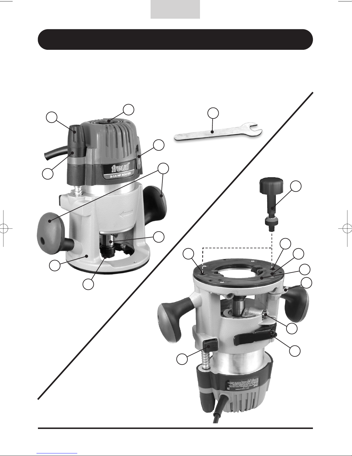
FUNCTIONAL DESCRIPTION
English
A - Micro Adjust Dial
B - Micro Adjusting Knob
C - Variable Speed Control
D - On/Off Switch
E - Side Handles
F - Spindle
G - Collet
H - Fixed Base
I - 22mm Wrench
J
L
Q
M
R
N
O
P
J - Above Table Height
Adjustment Access
K - Depth Adjustment Wrench
L - Above Table Base Clamp Access
M - Base Plate
N - Spindle Lock
(Shaft Lock)
O - Base Clamp
P - Base Release Button
Q - Spindle Lock Access
R - Locking Lever
K
B
A
G
C
F
D
H
E
I

8
SYMBOLS
Some of the following symbols may be used on your tool. Please study them and learn their
meaning. Proper interpretation of these symbols will allow you to operate the tool better and
more safely.
English
Symbol Name Designation/Explanation
V Volts Voltage (potential)
A Amperes Current
Hz Hertz Frequency (cycles per second)
W Watt Power
n
o No load speed Rotational speed, at no load
.../min Revolutions or reciprocation per minute Revolutions, strokes, surface speed,
orbits, etc. per minute
Class II construction Designates double insulated construction
tools
Alternating current Type or a characteristic of current
Safety Alert Precautions that involve your safety
Power Source Single-Phase, 120V, AC 60Hz
Amps 13
Watts 1500
No-Load Speed 10,000-23,000 RPM
Collet 1/4 inch & 1/2 inch
Max Bit Diameter* 3-1/2 inch (89 mm)
Weight 5.4 lbs
SPECIFICATIONS
* Router bits over 11/2” diameter should be used only with the router mounted in a router table. The router base
plate must be removed to to accept bits larger 21/2” diameter. Consult the router table’s user manual for
maximum bit diameter that can be used in the router table.

9
ASSEMBLY & OPERATION
PRIOR TO OPERATION
1. Check Power Supply
Ensure that the power source to be utilized conforms to the power source requirements
specified on the tool nameplate. Ensure the receptacle being used accepts the plug tightly. If
a faulty receptacle is used, it may cause overheating, resulting in a serious hazard.
2. Check Work Area
Confirm that the work site is placed under appropriate conditions conforming to precautions
prescribed in the safety section of this manual.
3. Before Plugging in the Tool
Ensure that the power tool switch (D) is in the OFF position to prevent the tool from accidental
start up which could cause serious injury.
INSTALLING AND REMOVING THE BIT (2 OPTIONS)
WARNING: Disconnect tool from power source. Make sure the correct collet is selected to
match the bit shank diameter before proceeding.
Option 1 – Hand Held Use
a) Open base clamp (O) on the router base (H). - Fig 1a
b) While pressing the router base release button (M), push down the router handles until the
entire collet extends past the base. Rotate Locking Lever (R) until it engages the Spindle
Lock (N) - Fig 1b
English
Fig. 1a Fig. 1b
1
3
2
10
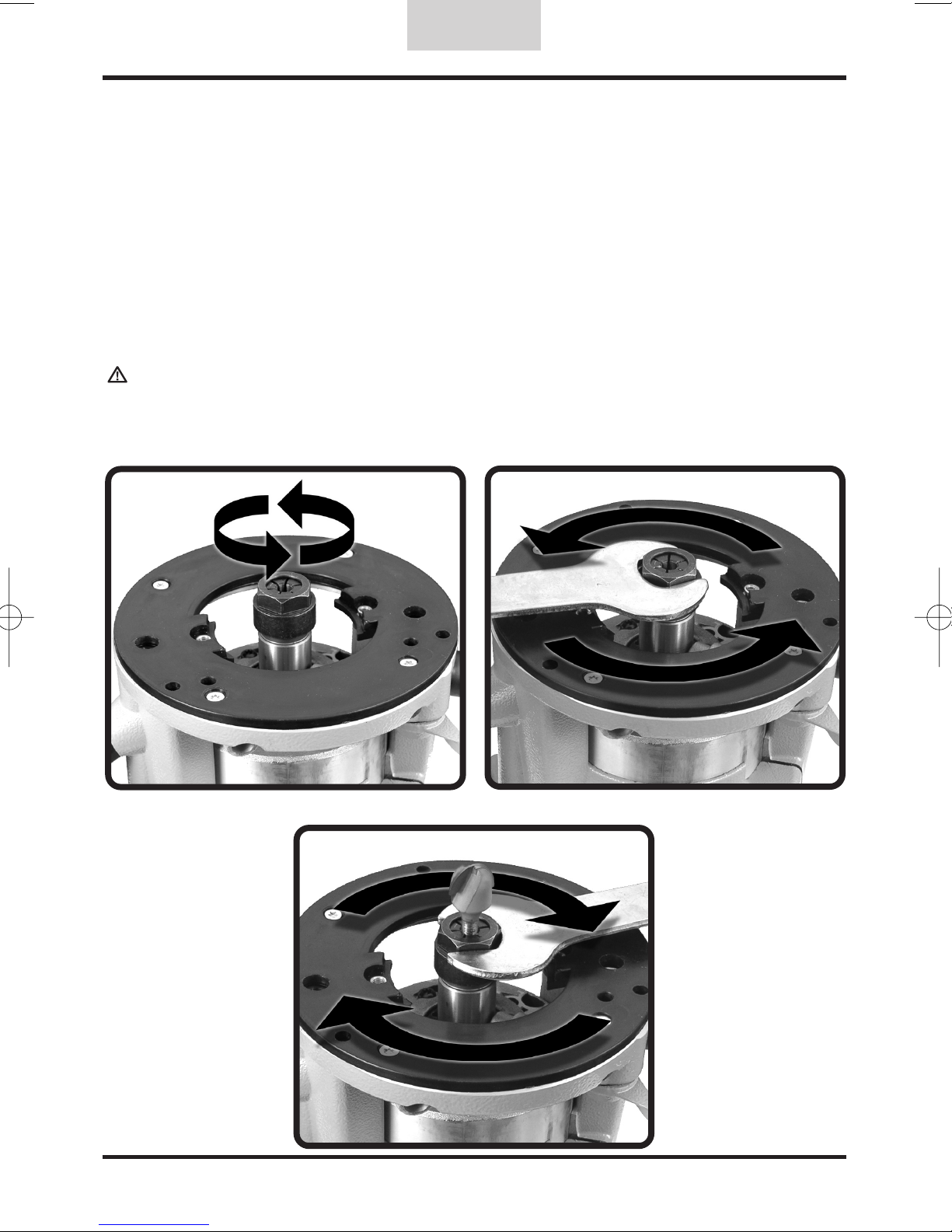
c) Rotate collet until the spindle lock pin engages with the spindle (F). When the locking pin
engages, you will not be able to rotate the spindle. - Fig 1c
d) Using the included 22mm wrench (I), turn the collet nut (G) counterclockwise to loosen the
collet. - Fig 1d
e) Insert the router bit and rotate the collet nut with the 22mm wrench clockwise to
tighten the collet. Always be sure that 80% of the router bit shank is inserted in the collet
- Fig 1e
f) Rotate Locking Lever (R) until it disengages the Spindle Lock (N). Press the router base
release button and slide the router motor out of the base until the router bit is back below
the surface of the router base and close base clamp.
g) Before operating the router, follow directions in the section in this manual titled "Adjusting
Depth of Cut" to properly set your depth of cut.
h) To remove a router bit from the collet, follow steps b,c, and d and then remove the router bit.
WARNING: Failure to disengage the spindle lock or remove the wrench before operating this
power tool could result in injury or damage to the tool.
English
Fig. 1e
Fig. 1c
Fig. 1d

11
Option 2 – Through The Base Bit Changes
The Freud FT1700 can also be mounted to a router
table.To mount the router, please follow the
instructions included with the router table.
a) Unlock the base by inserting the height
adjustment wrench (K) into the above table base
clamp access hole (L) and turn counter clockwise
until the wrench stops turning. - Fig. 2a
b) Insert the depth adjustment wrench into the
above table height adjustment access hole (J)
and rotate counter clockwise until the collet (G)
extends fully through the base. - Fig. 2b
c) Insert the depth adjustment wrench into the
spindle lock access hole (Q) and rotate clockwise
until it stops. Rotate spindle (F) until spindle lock
pin (N) engages. When the spindle lock pin is
correctly engaged, you will not be able to rotate
the spindle. - Fig. 2c
d) Using the 22mm collet nut wrench (I), turn the
collet nut counter clockwise to loosen the collet.
If a bit is already in the collet, the collet nut will
loosen for approximately 1 turn and then become
tight again. Continue turning the nut counter
clockwise with the wrench until the nut is loose
again. At the point the bit should be released and
easy to remove from the collet. - Fig. 2d
e) To install a router bit, insert the bit into the collet
and with the 22mm wrench rotate the collet nut
clockwise to tighten the collet. Always be sure
that at least 80% of the router bit shank is
inserted in the collet but never allow the bit
shank to “bottom out” in the collet. - Fig. 2e
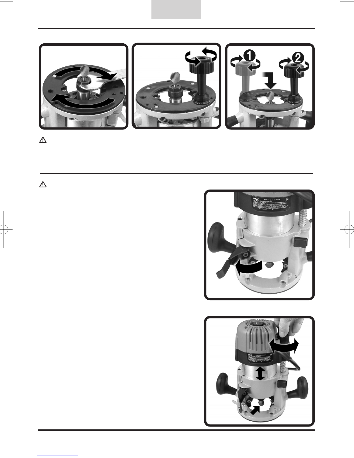
f) Insert the depth adjustment wrench into the
spindle lock access hole (Q) and rotate counter
clockwise until it stops turning.- Fig. 2f
g) 1. Insert depth adjustment wrench into the
above table height adjustment access hole (J)
and turn clockwise to lower the router bit.
2. Lock the base by inserting the height
adjustment wrench into the above table base
clamp access hole (L) and turn the wrench
clockwise until the wrench stops turning.
- Fig. 2g
h) Before operating the router, follow directions in
the section in this manual titled “Adjusting Depth
of Cut” to properly set your depth of cut.
English
Fig. 2a
Fig. 2b
Fig. 2c
Fig. 2d
12
WARNING: Failure to disengage the spindle lock or remove the wrench before operating this
power tool could result in injury or damage to the tool.
ADJUSTING DEPTH OF CUT (2 OPTIONS)
WARNING! Disconnect tool from power source.
Option 1 – Hand Held Use
a. Open the base clamp (O). - Fig. 3a
b. Turn the Micro Adjusting Knob until the bit
contacts the work surface making sure that
the router is level and flat. - Fig. 3b
c. Turn the Micro Adjustment Knob (B) clockwise to
the desired depth. (one complete rotation
varies the bit depth by 1/8").
d. Lock the base clamp (O) prior to operation.
English
Fig. 3a
Fig. 3b
Fig. 2e
Fig. 2f
Fig. 2g

13
Option 2– Through The Base Bit Changes
The Freud FT1700 can also be mounted to a
router table. To mount the router, please follow the
instructions included with the router table.
a) Unlock the base by inserting the height
adjustment wrench (K) into the above table base
clamp access hole (L) and rotate counter
clockwise until the wrench stops turning.
- Fig. 4a
b) Insert the depth adjustment wrench into the
above table height adjustment access hole (J).
Turn the wrench counter clockwise to raise the
bit and clockwise to lower the bit. - Fig. 4b
c) Once the bit is set at the desired depth of cut,
lock the base by inserting the height adjustment
wrench into the above table base clamp access
hole (L) and turn the wrench clockwise until the
wrench stops turning. - Fig. 4c
MOUNTING TEMPLATE GUIDES
WARNING! Disconnect tool from power source.
For template routing, the Freud FT1700 accepts
standard template guides which are available
separately. To use template guides an optional adapter
ring (Freud FT1100) must be attached to the base
plate using the two slotted screws provided. Remove
the slotted screws from the base plate, insert the
adapter ring with the flat side toward the router body.
Install and tighten the screws to secure the adapter
ring. - Fig. 5
The base plate (L) has been centered at the factory,
however, if the base plate has been removed and
remounted some adjustment may be necessary to
center the template guides to the router bit. To adjust,
loosen the four base plate screws that secure the base
plate to the router, reposition the base plate and
tighten the screws.
English
Base Plate
Screw
Adaptor Ring
Screws
Base
Plate Screw
Base Plate
Screw
Base
Plate Screw
Fig. 4a
Fig. 4b
Fig. 4c
Fig. 5
14
WARNING: Make sure that the voltage
from the power supply matches the voltage
specified on the tool. Before plugging in the
tool ensure that the bit is properly inserted
and tightened and that it spins freely.
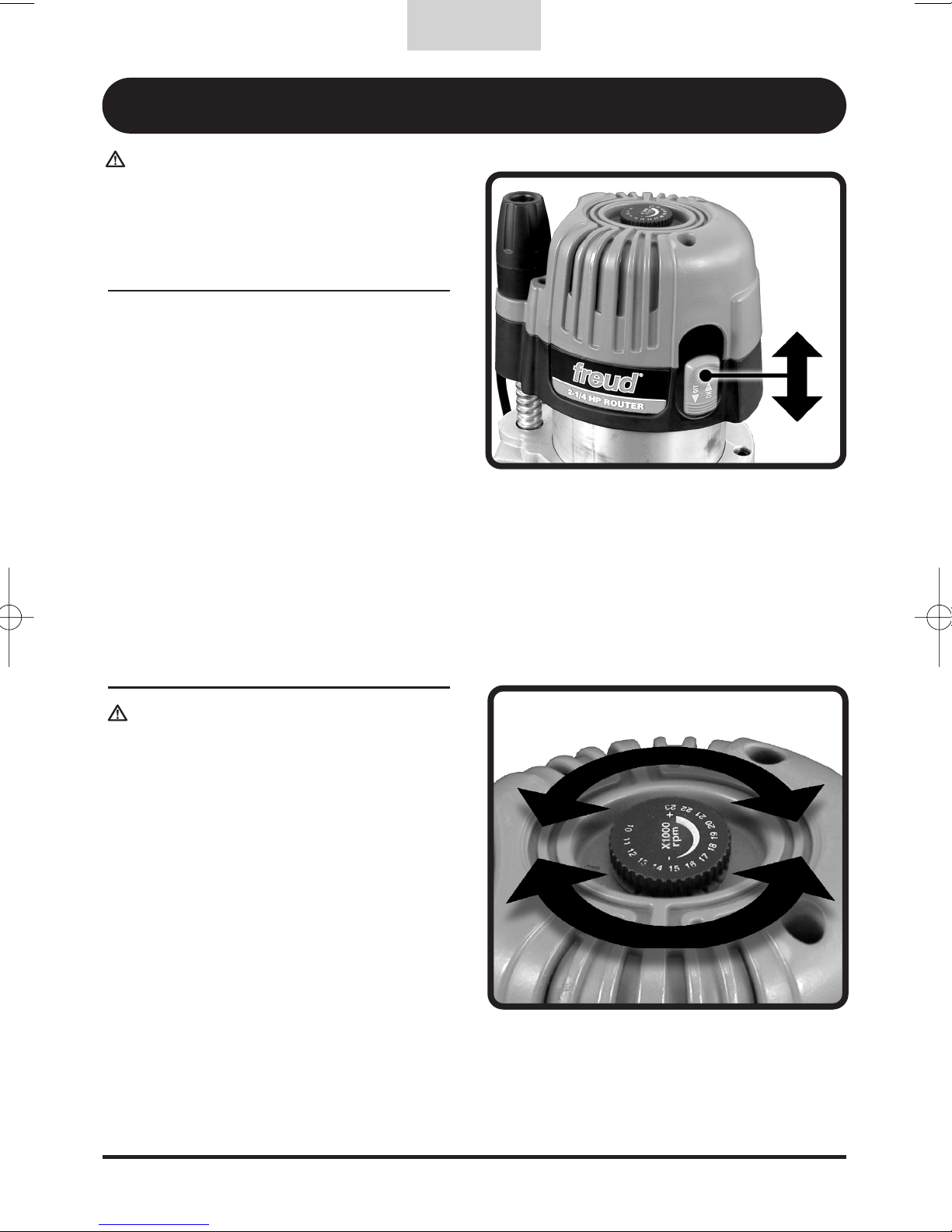
1. Starting the Tool
a) Plug in the tool with the switch in the
OFF position.
b) Hold the router firmly with both
handles with the bit away from you
and positioned so that the bit is not in
contact with the wood or any part of
your body or clothing.
c) Start the tool by sliding the switch in
the direction specified on the tool.
- Fig. 6
d) Turn off the tool by sliding the switch
in the opposite direction.
2. Variable Speed Control
WARNING: Always unplug the router
before making any speed adjustment.
The Freud FT1700 is equipped with an
electronic variable speed control feature.-
Fig. 7
This speed control has an infinite number of
speeds from 10,000 to 23,000 RPM. The
speed is adjusted by turning the speed
control knob (C). Consult the router bit
manufacturer for recommended bit speed.
The electronic speed control keeps constant
speed at all levels. If the motor speed
decreases in use you may be exceeding the
load capacity of the tool. This could cause
damage to the motor by overheating.
Reducing the depth of cut so that more
passes are required and/or slowing the rate
of feed will reduce the power requirements on
the router.
English
Fig. 7
Fig. 6
ON
OFF
OPERATING INSTRUCTIONS
15
CUTTING APPLICATIONS
Consider the material that you are cutting and
the amount of material that will be removed
before using the tool. Make sample cuts on
scrap wood before cutting the actual work piece.
WARNING! Always clamp your work piece
securely before making any cuts.
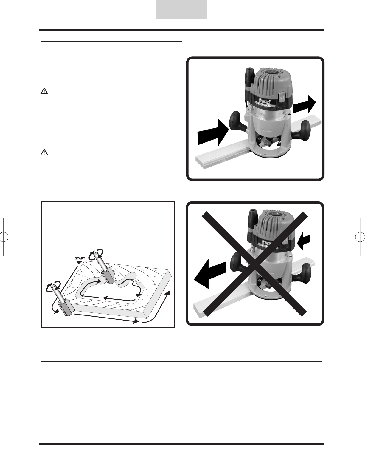
The router bit rotates in a clockwise direction
when viewed from the top of the router. On
external edge treatments move the router
counter clockwise from left to right. - Fig. 8a
WARNING! Avoid climb cutting (moving the
router clockwise with the rotation of the bit.
- Fig. 8b. Climb cutting increases the potential of
loosing control of the router and possible injury.
TABLE MOUNTING
The Freud FT1700 can also be mounted to a router table. To mount the router, please follow the
instructions included with the router table.
English
Fig. 8b
INCORRECT
Fig. 8a
CORRECT
Tip: When creating an edge treatment on all
four edges, begin with the end grain of the
board first. If tear out occurs at the end of
this cut it will be removed when the cut is
made along the edge or with the grain.

16
MAINTENANCE & INSPECTION
Service
It is recommended that all service on your Freud tool be performed by an
Freud Authorized service center. Service by unauthorized service personnel
may result in misplaced internal components resulting in risk of tool
malfunction and personal injury to the tool user.
Power Cord
Check that the power cord is in good condition. If it is not, have it replaced
immediately at a Freud Authorized service center.
Tool Lubrication
All power tools require care and attention. Every couple of years, or when
needed, it is recommended you take the tool to an Freud Authorized service
center for a general cleaning and lubrication.
Ventilation Openings
Make sure the air vents are always kept clean and free of obstacles. If
clogged, vacuum out obstruction. It is recommended that you blow off the
entire tool with compressed air after each use.
Bearings
Every two years, or when needed, the bearings should be inspected by a
Freud Authorized service technician. Bearings that become very noisy should
be replaced at once to avoid overheating or motor failure.
Inspect Accessories
Regularly inspect your router bits. Using worn accessories will diminish the
efficiency of the work and could damage the tool's motor.
Inspect Screws
Regularly inspect all screws in your power tool and make sure they are
properly tightened. Loose screws should be retightened immediately.
English

17
To locate a Freud Authorized Service Center near you, call: 1-800-334-4107
Or visit our web site at: www.freudtools.com
In Canada call: 1-800-263-7016
Or visit the Canadian site for a full list of service centers at: www.freud.ca
Standard Accessories
• Collet Nut Wrench
• Depth Adjustment Wrench
• 1/4" and 1/2" Collets
• Vacuum Adaptor
• Carrying Case
English
ACCESSORIES
Service Locations

18
NORTH AMERICAN POWER TOOL WARRANTY
FREUD LIMITED POWER TOOL WARRANTY
90 DAY MONEY BACK GUARANTEE
If within the first 90 days from the date of original purchase you are not completely satisfied with your Freud
power tool for any reason you may return the tool (in its original packaging and complete with all accessories) to
the place of purchase with proof of purchase (e.g. dated sales receipt) for a full refund.
FREUD LIMITED FIVE YEAR POWER TOOL WARRANTY
Freud warrants to the original consumer purchaser that each new Freud power tool shall be free from defects in
material and workmanship for a period of five (5) years from the purchase date. When warranty service is
requested, proof of purchase (e.g. dated sales receipt) is required. Should the power tool fail within ninety (90)
days from the date of purchase, it will be repaired or replaced AT THE CUSTOMER'S OPTION subject to the
guidelines below. Thereafter, upon verification of failure or malfunction, at Freud's option, Freud will repair or
replace the power tool, subject to the guidelines below. This warranty does not cover damage incurred from
repair or attempted repair by anyone other than Freud's authorized personnel, normal wear and tear, abuse, lack
of maintenance, or accidents.
FREUD WARRANTY GUIDELINES
1. In the event of failure or malfunction, return the product, properly packaged and postage prepaid, to Freud at
the address listed below or to an authorized Freud service station. For technical advice, instructions on returns,
or a list of authorized repair stations, please contact us at (U.S.) 1-800-334-4107 (Canada) 1-800-263-7016.
2. All implied warranties for Freud power tools (INCLUDING MERCHANTABILITY AND FITNESS FOR
PARTICULAR PURPOSE) are limited to the period of three years from the purchase date by the original
consumer purchaser. Some states do not allow limitations on how long an implied warranty lasts, so the above
limitation may not apply to you.
3. A warranty claim shall be limited to repair or replacement as stated in Freud's Limited Power Tool Warranty,
and in no event shall Freud be liable for any other direct, indirect, incidental or consequential damages, costs or
expenses. INCIDENTAL AND CONSEQUENTIAL DAMAGES ARE EXCLUDED UNDER ALL WARRANTIES. Some
States do not allow the exclusion or limitation of incidental or consequential damages, so the above limitation or
exclusion may not apply to you.
4. Freud's warranties give you specific legal rights, and you may also have other rights which vary from State to
State.
5. Freud's warranties shall not be deemed to have failed their essential purpose while Freud is willing to repair or
replace defective products.
6. Freud assumes no liability for defects or damage caused by abuse or misuse of any product or unauthorized
service of any product. The product must have been used for its recommended purpose and not modified or
changed. Normal wear and tear is not covered under Freud's warranties.
7. Any legal action for breach of warranty must be commenced within one year after the claim has arisen.
8. All warranties are expressly limited to the original consumer purchaser. All warranties and other rights of the
purchaser shall be governed under the laws of the State of North Carolina without regard to conflict of law
principles.
To obtain service under Freud Limited Power Tool Warranty, contact an authorized repair station or:
Freud America, Inc.
(Attn: Technical Service)
218 Feld Avenue
High Point, North Carolina 27263
1-800-334-4107
Freud Canada
(Attn: Technical Service)
7450 Pacific Circle
Mississauga, Ontario L5T 2A3
Canada
1-800-263-7016
(c) Copyright 2007, Freud America, Inc. All rights reserved.
English

19
NOTES:
English

20
NOTICE TECHNIQUE D’UTILISATION
Français
AVERTISSEMENT : Pour réduire les risques de blessure, l’utilisateur doit lire et comprendre
les consignes d’utilisation avant d’utiliser ce produit.
Toupie 2-1/4 HP FT1700VCE

21
SÉCURITÈ
AVERTISSEMENT! Lire attentivement et comprendre toutes les instructions. Le non respect
des instructions peut entraîner des risques de décharge électrique, d’incendie et (ou) de blessure
corporelle grave.
CONSERVER CES INSTRUCTIONS
RÈGLES GÉNÉRALES DE SÉCURITÉ
1. Aire de travail
a) Garder l’aire de travail propre et bien éclairée. L’encombrement et un mauvais éclairage sont
propices aux accidents pouvant causer des blessures corporelles.
b) Ne pas utiliser d’outils mécaniques dans un milieu déflagrant tel qu’en présence de liquide
inflammable, de gaz ou de poussière. Les outils mécaniques génèrent des étincelles qui
peuvent enflammer la poussière ou les vapeurs.
c) Garder éloignés les tiers, les enfants et les visiteurs pendant l’utilisation d’un outil
mécanique. Les distractions peuvent entraîner une perte de contrôle par l’utilisateur.
2. Règles de sécurité en matière d’alimentation
a) Les outils à double isolation sont dotés d’une fiche polarisée (une branche de la fiche est
plus large que l’autre). Ce type de fiche ne peut être branché que d’une seule façon dans
une prise de courant polarisée. Si la fiche ne peut être insérée complètement dans la prise,
inverser la fiche. Si la fiche ne peut toujours pas être correctement insérée, communiquer
avec un électricien qualifié et lui demander d’installer une prise de courant polarisée. Ne
jamais changer la fiche, d’aucune façon. La double isolation élimine le besoin d’utiliser un
cordon d’alimentation à trois fils et d’une source d’alimentation avec mise à la terre.
b) Éviter le contact corporel avec les surfaces mises à la terre telles que les tuyaux, les
radiateurs, les cuisinières et les réfrigérateurs. Le contact corporel avec les surfaces mises à
la terre augmente le risque de décharge électrique.
c) Ne pas exposer les outils mécaniques à la pluie. Ne pas utiliser les outils mécaniques dans
un endroit humide ou détrempé. L’eau entrant en contact avec un outil mécanique augmente
le risque de décharge électrique.
d) Prendre soin du cordon d’alimentation. Ne jamais transporter un outil en le tenant par le
cordon d’alimentation et ne jamais tirer sur le cordon pour retirer la fiche d’une prise. Tenir le
cordon à l’écart de la chaleur, de l’huile, des arêtes vives et des pièces en mouvement.
Remplacer immédiatement un cordon d’alimentation endommagé. Un cordon d’alimentation
endommagé augmente le risque de décharge électrique.
e) À l’extérieur, utiliser une rallonge électrique de catégorie « W-A » ou « W ». Ces rallonges
sont certifiées pour utilisation à l’extérieur et réduisent les risques de décharge électrique.
3. Sécurité personnelle
a) Demeurer vigilant, être attentif à ce que l’on fait et faire preuve de bon sens lorsqu’on utilise
un outil mécanique. Ne pas utiliser un outil lorsqu’on est fatigué ou sous l’influence de
drogues, d’alcool ou de médicaments. Un moment d’inattention peut être source de graves
blessures corporelles.
b) Porter des vêtements adéquats. Ne pas porter de vêtements amples ou de bijoux. Porter un
filet protecteur pour contenir les cheveux longs. Tenir les cheveux, vêtements et gants à
l’écart des pièces en mouvement. Les vêtements amples, les bijoux ou les cheveux longs
peuvent être happés par les pièces en mouvement. Des gants de caoutchouc et des
chaussures antidérapantes sont recommandés pour les travaux extérieurs.
c) Éviter les mises en marche non intentionnelles. S’assurer que l’interrupteur est à la position
(ARRÊT) avant de brancher un outil. Ne pas transporter un outil avec un doigt sur
l’interrupteur et éviter de brancher un outil dont l’interrupteur est à la position Marche.
d) Prendre l’habitude de s’assurer que les clés de réglage sont retirées avant de mettre l’outil
en marche. Une clé oubliée près d’une pièce mobile ou rotative peut causer des blessures
corporelles.
e) Garder son équilibre. Garder une pose des pieds adéquate et son équilibre en tout temps.
Une pose des pieds adéquate et un bon équilibre assurent un meilleur contrôle de l’outil, en
Français

22
toute situation.
f) Utiliser l’équipement de sécurité adéquat. Toujours porter des lunettes de protection. Utiliser
un masque facial ou anti-poussières si l’activité de coupe génère de la poussière.
4. Utilisation et maintenance de l’outil
a) Fixer la pièce sur laquelle on travaille. Utiliser des serres ou des pinces étau pour fixer la
pièce sur un support stable. L’utilisation de serres ou de pinces étau permet d’utiliser les
deux mains pour manier l’outil. Tenir la pièce à la main ou l’appuyer contre son corps est
une procédure instable qui peut engendrer une perte de contrôle.
b) Ne pas forcer l’outil. L’outil mécanique offre un meilleur rendement et est plus sécuritaire
lorsqu’il est utilisé à l’intensité pour laquelle il a été conçu.
c) Utiliser l’outil approprié au travail. Ne pas utiliser un outil mécanique pour un travail pour
lequel il n’a pas été conçu.
d) Ne pas utiliser l’outil si l’interrupteur ne peut en contrôler la mise en marche ou l’arrêt. Tout
outil ne pouvant être contrôlé au moyen de son interrupteur est dangereux et doit être
réparé. Un interrupteur défectueux doit être remplacé à un centre de service Freud autorisé.
e) Débrancher la fiche de la source d’alimentation quand l’outil n’est pas utilisé, avant sa
maintenance et avant de remplacer ou de changer un accessoire tel qu’une lame, un foret
ou un couteau. Le respect des mesures de sécurité préventives réduit le risque de mise en
marche accidentelle de l’outil et de blessure corporelle.
f) Ranger les outils non utilisés. Les outils doivent être rangés dans un endroit sec, élevé ou
verrouillé et hors de portée des enfants.
g) Prendre soin de ses outils. Garder les outils de coupe aiguisés et propres pour assurer un
meilleur rendement et une meilleure sécurité. Suivre les instructions pour lubrifier l’outil et
changer les accessoires. Inspecter régulièrement le cordon d’alimentation. Un cordon
d’alimentation endommagé doit être remplacé à un centre de service Freud autorisé.
Inspecter périodiquement les rallonges électriques et remplacer les rallonges endommagées.
Tenir les poignées sèches et propres, exemptes d’huile ou de graisse. Les outils
correctement entretenus, dotés de lames bien aiguisées, sont moins susceptibles de bloquer
et plus faciles à contrôler.
h) Vérifier la présence de pièces endommagées. Avant de continuer à utiliser l’outil, un
protecteur ou autre élément endommagé doit être inspecté pour déterminer s’il peut
fonctionner correctement et assurer sa fonction. Vérifier l’alignement des pièces mobiles, le
montage et les autres composants qui peuvent avoir une incidence sur l’utilisation de l’outil.
Un protecteur ou autre composant endommagé doit être réparé ou remplacé à un centre de
service Freud autorisé, à moins d’indication contraire dans le présent manuel d’utilisation.
i) N’utiliser que les accessoires recommandés par le fabricant pour le modèle d’outil utilisé. Des
accessoires adaptés à un outil donné peuvent être source de danger s’ils sont utilisés avec
un autre outil.
5. Service
a) Le service doit être assuré uniquement par un centre de service Freud autorisé. Le service
ou la maintenance exécuté par du personnel non qualifié peut entraîner des risques de
blessure.
b) Pour la maintenance d’un outil, n’utiliser que des pièces de remplacement identiques. Suivre
les instructions figurant à la section Maintenance du présent manuel. L’utilisation de pièces
non autorisées ou le non respect des instructions relatives à la maintenance peut entraîner
des risques de décharge électrique ou de blessure corporelle. Certains produits de
nettoyage tels que l’essence, le tétrachlorure de carbone, l’ammoniac, etc., peuvent
endommager les pièces en plastique.
RÈGLES DE SÉCURITÉ ADDITIONNELLES POUR TOUPIE
• AVERTISSEMENT! Ne pas défoncer de matériaux contenant de l’amiante. La poussière
dégagée lors de la défonce de matériaux contenant de l’amiante et (ou) de la silice contient
des produits chimiques dangereux pour la santé. Éviter d’inhaler cette poussière et se
conformer aux règles de prévention des accidents.
• Bien serrer l’écrou du collet pour éviter que le couteau glisse hors de son logement.
• Pour les coupes de part en part, laisser un espace suffisant sous le matériau coupé pour
permettre le passage du couteau.
• S’assurer que les clés de réglage sont retirées avant de mettre l’outil en marche. Une clé
Français

23
attachée à une pièce rotative de l’outil peut causer des blessures corporelles.
• Ne jamais serrer l’écrou du collet si aucun couteau n’est installé.
• Ne jamais faire une coupe de droite à gauche, cela augmente le risque de perdre le contrôle
de l’outil et peut causer des blessures corporelles.
• Ne jamais travailler à bout de bras. Garder une pose des pieds adéquate et son équilibre en
tout temps pour assurer un meilleur contrôle de l’outil dans les situations imprévues.
• Ne pas perforer le boîtier de cet outil mécanique, cela pouvant détruire le dispositif
d’isolation contre les décharges électriques (utiliser des étiquettes adhésives).
• Toujours débrancher l’outil avant de changer un couteau ou de travailler sur l’outil.
• Pour arrêter l’outil, utiliser toujours l’interrupteur Marche/Arrêt plutôt que de le débrancher.
• AVERTISSEMENT! Avant chaque utilisation, vérifier la fiche et le cordon d’alimentation. S’ils
doivent être remplacés, s’adresser à un centre de service Freud autorisé.
• Toujours tenir le cordon d’alimentation et la rallonge électrique à l’écart de la zone de travail.
• Avant de brancher l’outil, toujours s’assurer que l’interrupteur est à la position Arrêt.
• Toujours tenir fermement l’outil à deux mains et maintenir une position stable ou utiliser une
table pour toupie.
• Régler la vitesse en fonction du diamètre du couteau. Plus le couteau est gros, moins la
vitesse est élevée.
• Les couteaux à toupie doivent être manipulés et entreposés avec le plus grand soin,
conformément aux instructions du fabricant.
• Vérifier soigneusement les couteaux avant de les utiliser pour s’assurer qu’ils ne sont pas
endommagés ou fissurés. Remplacer immédiatement un couteau endommagé ou fissuré.
• S’assurer que le couteau est inséré dans le mandrin conformément aux instructions du
fabricant.
• Avant d’utiliser l’outil, s’assurer que le couteau est correctement inséré et solidement fixé.
Mettre en marche l’outil libre de charge et le laisser tourner quelques secondes en position
sécuritaire. Arrêter immédiatement l’outil si des vibrations anormales sont ressenties ou si un
défaut est décelé.
• Utiliser seulement les collets et écrous de collet approuvés par Freud pour le montage des
couteaux dans le mandrin.
• Avant de procéder à la coupe, s’assurer que le matériau à couper est solidement fixé.
• Se protéger des rognures qui sont éjectées pendant la coupe. Tenir l’outil de façon à ce que
les copeaux soient expulsés dans la direction opposée à l’utilisateur.
• Pour la coupe de matériaux qui peuvent irriter la peau, les yeux ou les voies respiratoires,
utiliser l’équipement de dépoussiérage et porter un masque.
• Pour utiliser l’outil, toujours porter des lunettes de sécurité et des protecteurs auriculaires.
Les autres équipements de sécurité personnelle tels que les masques anti-poussière, les
tabliers et les chaussures antidérapantes doivent être également portés.
• S’assurer que les ouvertures d’aération sont libres de poussière et de débris. Si elles doivent
être nettoyées, débrancher d’abord l’outil et utiliser un aspirateur. Pour éviter d’endommager
les pièces internes de l’outil, ne jamais utiliser d’objets métalliques pour les nettoyer.
• Ne pas toucher aux couteaux quand ils tournent.
• AVERTISSEMENT! Les couteaux continuent à tourner longtemps après que l’interrupteur ait
été mis à la position Arrêt. S’assurer que le couteau a cessé de tourner avant de déposer
l’outil ou de changer les accessoires.
DOUBLE ISOLATION
Pour assurer une utilisation sécuritaire de cet outil, Freud a adopté une solution de conception à
double isolation. « Double isolation » signifie que deux systèmes d’isolation physiquement séparés
ont été utilisés pour isoler le matériel conducteur d’électricité raccordé à l’alimentation du corps
extérieur tenu par l’utilisateur.
Pour préserver l’efficacité du système à double isolation, suivre les précautions suivantes :
• S’assurer de ne pas percer le boîtier du moteur, cela peut nuire à l’efficacité du système à
double isolation.
• Seuls les centres de service Freud autorisés doivent désassembler et assembler cet outil
mécanique et seules des pièces de rechange Freud d’origine doivent être installées.
Français

24
DESCRIPTION ET SPÉCIFICATIONS
Français
DESCRIPTION FONCTIONNELLE
A – Molette de réglage
micrométrique
B – Poignée de réglage
micrométrique
C – Cadran de réglage des
vitesses
D – Interrupteur Marche/Arrêt
E – Poignées de guidage
F – Arbre de rotation
G – Collet
H – Base fixe
I – Clé 22 mm
J
N
O
P
J – Accès au réglage de la
hauteur au-dessus de la table
K – Clé de réglage de la profondeur
L – Accès au réglage de la hauteur
au-dessus de la table
M – Semelle
N – Verrou de l’arbre de rotation (arrêt
pour essieu)
O – Bride de fixation de la base
P – Bouton de dégagement de la base
Q – Accès au blocage du mandrin
R – Levier de blocage
K
B
A
G
C
F
D
H
E
I
L
Q
M
R

25
Français
SYMBOLES
Certains des symboles suivants peuvent être utilisés sur l’outil. Étudier ces symboles et apprendre
leur signification. L’interprétation correcte de ces symboles permet d’utiliser l’outil plus
efficacement et de façon plus sécuritaire.
Symbole Nom Désignation / Explication
V Volts Tension (potentiel)
A Ampères Courant
Hz Hertz Cadence (cycles par seconde)
W Watt Puissance
n
o
Vitesse à vide Vitesse de rotation à vide
.../min Révolutions ou va-et-vient par minute Révolutions, courses, vitesse périphérique,
orbites, etc. par minute
Conception de classe 2 Désigne un outil à double isolation
Courant alternatif (c.a.) Type ou caractéristique du courant
Avertissement de sécurité
Précautions relatives à la sécurité de
l’utilisateur
Alimentation Monophasée 120V, c.a., 60HZ
Intensité 13 ampères
Puissance 1500 watts
Vitesse à vide 10 000 – 23 000 tr/min
Collet 1/4" po et 1/2” po
Diamètre maximal pour couteau 3-1/2" po (89 mm)
Poids 5,4 lbs
SPÉCIFICATIONS
* Pour utiliser des couteaux dont le diamètre est supérieur à 1-1/2" po, la toupie doit être montée sur
une table pour toupie. Pour les couteaux dont le diamètre est supérieur à 2-1/2" po, la semelle de la
toupie doit être enlevée. Voir le manuel d’instruction du fabricant de la table pour toupie pour le
diamètre maximal des couteaux pouvant être utilisés avec la table pour toupie.

26
ASSEMBLAGE ET UTILISATION
AVANT L’UTILISATION
1. Vérifier la source d’alimentation
S’assurer que la source d’alimentation est conforme aux spécifications figurant sur la plaque
signalétique de l’outil. S’assurer que la prise de courant est bien adaptée à la fiche. Une prise
défectueuse peut causer une surchauffe et constituer une source de grave danger.
2. Vérifier l’aire de travail
S’assurer que l’aire de travail est conforme aux précautions énoncées à la section Sécurité du
présent manuel.
3. Avant de brancher l’outil
S’assurer que l’interrupteur de l’outil mécanique
(D) est à la position ARRÊT pour éviter une mise
en marche accidentelle pouvant causer de graves
blessures corporelles.
INSTALLATION ET RETRAIT DES COUTEAUX
(2 CHOIX)
Avertissement! Débrancher l’outil de la source
d’alimentation. Avant de procéder, s’assurer que le
collet choisi est approprié au diamètre de la tige du
couteau.
(Choix 1) – Utilisation manuelle
a) Sur la base du routeur (H), ouvrir la bride de
fixation (O). – Fig. 1a
b) Presser sur le bouton de dégagement de la base
(M) et pousser les poignées de guidage
vers le bas jusqu’à ce que le collet dépasse de la
base. Tourner le levier de blocage (R) jusqu’à ce
que le système de blocage du mandrin (N) soit
engagé. – Fig. 1b
c) Tourner le collet jusqu’à ce que la tige de
verrouillage s’engage dans l’arbre de rotation (F).
Une fois la tige engagée, il n’est plus possible de
tourner l’arbre. – Fig. 1c
d) Au moyen de la clé 22 mm (I) fournie, tourner
l’écrou du collet (G) dans le sens anti-horaire
pour desserrer le collet. – Fig. 1d
Français
Fig. 1a
Fig. 1b
Fig. 1c
1
3
2

27
e) Insérer le couteau et, au moyen de la clé 22 mm,
tourner l’écrou du collet dans le sens horaire
pour resserrer le collet. Toujours s’assurer qu’au
moins 80 % de la tige du couteau est inséré
dans le collet. – Fig. 1e
f) Tourner le levier de blocage (R) jusqu'à ce que le
système de blocage du mandrin (M) soit dégagé.
Presser le bouton de dégagement de la base,
sortir le moteur de la base jusqu’à ce que le
couteau revienne sous la surface de la base et
fermer la bride de fixation de la base.
g) Avant d’utiliser la toupie, suivre les instructions
figurant à la section Réglage de la profondeur de
coupe du présent manuel.
h) Pour enlever un couteau du collet, suivre les
étapes b, c, et d puis retirer le couteau.
AVERTISSEMENT! Avant d’utiliser l’outil, s’assurer
de désengager le verrou de l’arbre de rotation et de
retirer la clé de serrage pour éviter les blessures
corporelles ou d’endommager l’outil.
(Choix 2) – Utilisation avec la table de toupie
La toupie Freud FT1700 peut aussi être montée sur une
table pour toupie. Pour le montage, voir les instructions
fournies avec la table pour toupie.
a) Pour ouvrir la base, insérer la molette
d’ajustement de la hauteur (K) dans le trou de
déblocage de la base situé au dessus de la table
(L) et tourner en sens inverse des aiguilles d’une
montre jusqu’à ce que la molette ne puisse plus
tourner. – Fig. 2a
b) Insérer la molette d’ajustement de la profondeur
dans le trou d’accès d’ajustement de la hauteur
par le dessus de la table (J) et tourner en sens
inverse des aiguilles d’une montre jusqu’à ce que
le collet (G) dépasse complètement au dessus de
la base. – Fig. 2b
c) Insérer la molette d’ajustement de la profondeur
dans le trou d’accès du blocage du mandrin (Q)
et tourner dans le sens des aiguilles d’une
montre jusqu’à l’arrêt complet de la molette.
Tournez le mandrin (F) jusqu’à ce que la cheville
de blocage du mandrin (N) soit engagée. Quand
la cheville de blocage est bien engagée, il est
impossible de tourner le mandrin. – Fig. 2c
d) Utiliser la clé à mandrin de 22mm (I) et tourner
l’écrou en sens inverse des aiguilles d’une montre
Français
Fig. 2a
Fig. 2b
Fig. 1d
Fig. 1e

28
pour desserrer le collet. Si une mèche est déjà
insérée dans le collet, l’écrou se desserrera
après un tour et se serrera de nouveau.
Continuez de tourner l’écrou en sens inverse des
aiguilles d’une montre avec la clé à mandrin
jusqu’à ce que l’écrou soit complètement
desserré. À ce point, la mèche devrait être
relâchée et facile à retirer du collet. – Fig. 2d
e) Pour installer une mèche de toupie, insérer la
mèche dans le collet, et avec la clé à mandrin de
22mm tournez l’écrou dans le sens des aiguilles
d’une montre. Il faut toujours s’assurer que 80 %
de la tige de la mèche de toupie soit insérée dans
le collet sans jamais laisser la tige toucher le
fond du collet. – Fig. 2e
f) Insérer la molette d’ajustement de la profondeur
dans le trou d’accès du blocage du mandrin (Q)
et tourner en sens inverse des aiguilles d’une
montre jusqu’à l’arrêt de la molette. – Fig. 2f
g) 1. Insérer la molette d’ajustement de la
profondeur dans le trou d’accès d’ajustement de
la hauteur par le dessus de la table (J) et tourner
dans le sens des aiguilles d’une montre pour
baisser la mèche de toupie. 2. Bloquer la base
en insérant la molette d’ajustement de la hauteur
dans le trou de blocage, par le dessus de la table
(L) et tourner dans le sens des aiguilles d’une
montre jusqu’à ce que la molette ne puisse plus
tourner. – Fig. 2g
h) Avant d’utiliser la toupie, assurez vous de suivre
les directives dans la section du manuel ‘Ajuster
la profondeur de coupe afin de bien régler la
profondeur de coupe.
AVERTISSEMENT! Avant d’utiliser l’outil, s’assurer
de désengager le verrou de l’arbre de rotation et de
retirer la clé de serrage pour éviter les blessures
corporelles ou d’endommager l’outil.
Français
Fig. 2c
Fig. 2d
Fig. 2e
Fig. 2f
Fig. 2g

29
AJUSTER LA PROFONDEUR DE COUPE
AVERTISSEMENT! Débrancher l’outil de la source
d’alimentation.
(Choix 1) – Utilisation manuelle
a) Ouvrir la bride de fixation de la base (O). –Fig. 3a
b) En s’assurant que la toupie est bien à plat et au
niveau, tourner la poigné de réglage
micrométrique (B) jusqu’à ce que le couteau
entre en contact avec la surface de travail.
- Fig. 3b
c) Tournée la poignée de réglage micrométrique
dans le sens horaire jusqu’à la position désirée
(une rotation complète déplace le couteau de 1/8
de pouce).
d) Fermer la bride de fixation de la base (O).
(Choix 2) – Utilisation avec la table de toupie
a) Pour ouvrir la base, insérer la molette
d’ajustement de la hauteur (K) dans le trou de
déblocage de la base situé au dessus de la table
(L) et tourner en sens inverse des aiguilles d’une
montre jusqu’à ce que la molette ne puisse plus
tourner. – Fig. 4a
b) Insérer la molette d’ajustement de la profondeur
dans le trou d’accès d’ajustement de la hauteur
par le dessus de la table (J). Tourner la molette
dans le sens inverse des aiguilles d’une montre
pour monter la mèche et tourner en sens des
aiguilles d’une montre pour baisser la mèche.
– Fig. 4b
c) Quand la mèche est ajustée à la profondeur de
coupe désirée, bloquer la base en insérant la
molette d’ajustement de la hauteur dans le trou
de blocage, par le dessus de la table (L) et
tourner dans le sens des aiguilles d’une montre
jusqu’à ce que la molette ne puisse plus tourner.
–Fig. 4c
Français
Fig. 3a
Fig. 3b
Fig. 4a
Fig. 4b Fig. 4c

30
MONTAGE DES GUIDES POUR GABARIT
AVERTISSEMENT! Débrancher l’outil de la
source d’alimentation.
Pour le toupillage avec gabarit, la toupie Freud
FT1700 accepte les guides pour gabarit standards
vendus séparément. Pour utiliser les guides pour
gabarit, un anneau adaptateur (FT1100) offert en
option doit être fixé à la semelle au moyen de deux
vis à filets interrompus (fournies). Enlever les vis à
filets interrompus de la semelle et placer l’anneau
adaptateur, le côté plat face au corps de la toupie.
Mettre les vis et les serrer pour fixer l’anneau.
– Fig. 5
La semelle (L) a été centrée en usine. Cependant, si
la semelle a été enlevée puis replacée, certains
ajustements peuvent être requis pour centrer le
guide autour du couteau. Pour ajuster, desserrer les
quatre vis qui fixent la semelle à la toupie,
repositionner la semelle et serrer les vis.
INSTRUCTIONS D’UTILISATION
AVERTISSEMENT! S’assurer que la tension de
la source d’alimentation correspond à celle indiquée
sur l’outil. Avant de brancher l’outil, s’assurer que le
couteau est correctement inséré et fixé et qu’il
tourne librement.
Démarrage de l’outil
a) Brancher l’outil, l’interrupteur à la position
Arrêt.
b) Tenir fermement la toupie avec les deux
mains, le couteau à l’écart de l’utilisateur et
placé de façon à ce qu’il ne touche pas à
la surface de travail, au corps de
l’utilisateur ou aux vêtements.
c) Démarrer l’outil en glissant l’interrupteur
dans la direction indiquée sur l’outil. – Fig. 6
d) Arrêter l’outil en glissant l’interrupteur dans
la direction opposée.
Réglage de la vitesse de rotation
AVERTISSEMENT! Toujours débrancher la
toupie avant de régler la vitesse.
La toupie Freud FT1700 est munie d’un dispositif
électronique de réglage de la vitesse de rotation.
– Fig. 7
Ce dispositif permet de sélectionner un nombre
quasi infini de vitesses allant de 10 000 à 23 000
tr/min. Pour ajuster la vitesse, tourner le cadran de
réglage de la vitesse (C). Voir les instructions du
fabricant des couteaux pour la vitesse
recommandée.
Le dispositif électronique de réglage de la vitesse
maintient une vitesse constante. Si la vitesse du
moteur diminue pendant l’utilisation, il est possible
que la capacité de charge de l’outil ait été excédée.
Le cas échéant, le moteur peut surchauffer et être
endommagé. Pour réduire la charge, réduire la
profondeur de coupe et faire plusieurs passes et (ou)
ralentir la coupe.
Français
Fig. 5
Fig. 6
ON
OFF
Vis de la
semelle
Vis de l’anneau
adaptateur
Vis de la
semelle
Vis de la
semelle
Vis de la
semelle
Fig. 7

31
APPLICATIONS DE COUPE
Avant d’utiliser l’outil, prendre en compte le
type de matériau et la quantité de matériau à
retirer. Avant de procéder à la coupe, faire
des coupes d’essai sur du matériau de rebut.
AVERTISSEMENT! Toujours bien fixer la
pièce à couper avant de procéder.
Vu du dessus de la toupie, le couteau tourne
dans le sens horaire. Pour les coupes sur les
bords extérieurs, déplacer la toupie dans le
sens anti-horaire, de gauche à droite.
– Fig. 8a
AVERTISSEMENT! Ne jamais faire une
coupe de droite à gauche (dans le sens de
rotation de la toupie) – Fig. 8b. Cela
augmente le risque de perte le contrôle de
l’outil et peut causer des blessures
corporelles
MONTAGE SUR TABLE
La toupie Freud FT1700 peut aussi être montée sur une table pour toupie. Pour le montage, voir
les instructions fournies avec la table pour toupie.
Français
Fig. 8b
INCORRECT
Fig. 8a
CORRECT
Truc : Pour l’ajustement des bords sur les
quatre côtés, commencer par le bout de
bois. Si des écornures se produisent à la fin
de cette coupe, elles seront éliminées avec
la coupe effectuée sur la rive (dans le sens
du grain).
Commencer

32
MAINTENANCE ET INSPECTION
Service
Il est recommandé que toute activité de maintenance de l’outil Freud soit
exécutée par un centre de service Freud autorisé. Les interventions effectuées
par du personnel non autorisé peuvent engendrer des défauts de mise en
place ou d’assemblage des composants internes causant un défaut de
fonctionnement de l’outil et constituant un risque de blessure corporelle pour
l’utilisateur.
Cordon d’alimentation
S’assurer que le cordon d’alimentation est en bon état. Un cordon
d’alimentation endommagé doit être immédiatement remplacé à un centre de
service Freud autorisé.
Lubrification
Tous les outils mécaniques requièrent soins et attention. Tous les deux ans, ou
au besoin, nous recommandons de laisser l’outil à un centre de service Freud
autorisé pour un nettoyage complet et sa lubrification.
Ouvertures d’aération
S’assurer que les ouvertures d’aération demeurent propres et non obstruées.
Nettoyer à l’air comprimé les ouvertures bouchées. Il est recommander de
nettoyer l’outil à l’air comprimé après chaque utilisation.
Roulements à bille
Tous les deux ans, ou au besoin, les roulements à bille doivent être inspectés
par un technicien Freud autorisé. Les roulements à bille bruyants doivent être
remplacées pour éviter la surchauffe et les pannes de moteur.
Inspection des accessoires
Inspecter régulièrement les accessoires utilisés avec la toupie. Des
accessoires endommagés ou émoussés réduisent l’efficacité de l’outil et
peuvent endommager son moteur.
Inspection des vis
Inspecter périodiquement toutes les vis pour s’assurer qu’elles sont bien
serrées. Les vis mal serrées doivent être immédiatement resserrées.
Français

33
Points de service
Pour connaître le centre de service Freud autorisé le plus près, composer le
numéro sans frais 1-800-334-4107 ou visiter notre site Web à l’adresse
www.freudtools.com.
Au Canada, composer le 1-800-263-7016 ou visiter notre site Web canadien
pour obtenir la liste complète de nos centres de service : www.freud.ca.
Accessoires standards :
• Clé pour écrou du collet
• Clé pour réglage de la profondeur de coupe
• Collets 1/4" et 1/2" pouce
• Adaptateur pour balayeuse
• Boîtier de transport
Français
ACCESSOIRES

34
Français
GARANTIE LIMITÉE POUR OUTIL MÉCANIQUE FREUD
GARANTIE DE 90 JOURS OU ARGENT REMIS
Si, dans les quatre-vingt-dix (90) jours suivant l’achat initial, vous n’êtes pas entièrement satisfait de
votre outil mécanique Freud, pour quelque raison que ce soit, vous pouvez le retourner, dans son
emballage d’origine et avec tous les accessoires, au magasin où vous l’avez acheté. Pour obtenir un
remboursement complet, présentez une preuve d’achat (par exemple, un reçu daté).
GARANTIE LIMITÉE DE CINQ ANS
Freud garantit à l’acheteur initial que chaque nouvel outil mécanique Freud demeure exempt de défaut
de fabrication et matériel pour une période de cinq (5) ans à compter de la date d’achat. Une preuve
d’achat (par exemple, un reçu daté) est requise pour les réparations sous garantie. Si l’outil s’avère
défectueux dans les quatre-vingt-dix (90) jours suivant la date d’achat, il sera remplacé ou réparé, AU
CHOIX DU CLIENT, conformément aux modalités ci-dessous. Passée la période de 90 jours, Freud,
après vérification du défaut de fonctionnement, à son choix, réparera ou remplacera l’outil,
conformément aux modalités ci-dessous. La présente garantie ne couvre pas les dommages causés par
les réparations effectuées ou tentées par qui que ce soit d’autre que le personnel Freud autorisé ou
résultant de l’usure normale, d’une utilisation abusive, d’un manque de maintenance ou d’un accident.
MODALITÉS DE LA GARANTIE FREUD
1. En cas de bris ou de défaut de fonctionnement, retourner le produit, adéquatement emballé et port
payé, à Freud à l’adresse indiquée ci-dessous ou à un point de service Freud autorisé. Pour obtenir des
conseils techniques, des instructions pour le retour ou la liste des points de service autorisés, composez
le 1-800-334-4107 aux États-Unis ou le 1-800-263-7016 au Canada.
2. Toutes les garanties implicites applicables aux outils mécaniques Freud (INCLUANT LA QUALITÉ
MARCHANDE ET L’ADAPTATION À UN USAGE PARTICULIER) sont limitées aux trois (3) années suivant
la date de l’achat initial. Certains États ou provinces n’autorisant pas les restrictions relatives à la durée
des garanties implicites, la présente restriction peut ne pas s’appliquer.
3. Toute réclamation au titre de la garantie se limite à la réparation ou au remplacement, tel qu’énoncé à
la garantie limitée Freud relative aux outils mécaniques. En aucun cas Freud peut-elle être tenue
responsable d’autres dommages, coûts ou dépenses directs, indirects ou consécutifs. LES PERTES
INDIRECTES ET LES DOMMAGES CONSÉCUTIFS SONT EXCLUS DE TOUTE GARANTIE. Certains
États ou provinces n’autorisant pas les restrictions relatives aux pertes indirectes et dommages
consécutifs, la présente restriction peut ne pas s’appliquer.
4. Les garanties Freud accordent au titulaire des droits spécifiques reconnus par la loi. Selon l’État ou la
province, le titulaire peut jouir d’autres droits qui peuvent varier d’un État ou province à l’autre.
5. Les garanties Freud ne peuvent être réputées avoir failli à leur objet premier alors que Freud est
disposée à réparer ou remplacer les produits défectueux.
6. Freud n’assume aucune responsabilité ou obligation quant aux défauts ou dommages causés par
l’utilisation abusive ou la mauvaise utilisation d’un produit ou par les interventions de maintenance non
autorisées. Le produit doit avoir été utilisé aux fins recommandées et ne pas avoir été modifié de
quelque façon que ce soit. Les garanties Freud ne couvrent pas l’usure normale d’un produit.
7. Toute poursuite pour inobservation de garantie doit être entreprise dans l’année suivant le dépôt de la
réclamation.
8. Toutes les garanties sont expressément limitées au consommateur acheteur initial. Toutes les
garanties et autres droits de l’acheteur sont régis en vertu des lois de l’État de la Caroline du Nord,
abstraction faite des principes inhérents aux conflits de lois.
Pour obtenir du service en vertu de la garantie limitée pour outil mécanique Freud, communiquez
avec un point de service autorisé ou avec :
Freud America, Inc.
(Attn: Technical Service)
218 Feld Avenue
High Point, North Carolina 27263
1-800-434-4107
Freud Canada
(Attn: Technical Service)
7450 Pacific Circle
Mississauga, Ontario L5T 2A3
Canada
1-800-263-7016
© Copyright 2007, Freud America, inc. Tous droits réservés.
GARANTIE EN AMÉRIQUE DU NORD

35
NOTES:
Français

36
INSTRUCCIONES DE OPERACIÓN
Español
ATENCION: Para reducir el riesgo de accídentes, el usuario debe leer y comprender las
Instrucciónes de Operación antes de usar este producto.
FT1700VCE 21/4 HP FRESADORAS

37
SEGURIDAD
ATENCIÓN: Lea y entienda todas las instrucciones. El no leer las instrucciones de abajo puede
resultar en choque eléctrico, fuego y/o heridas serias.
GUARDE ESTAS INSTRUCCIONES
REGLAS GENERALES DE SEGURIDAD
1. Area de trabajo
a) Mantenga su área de trabajo limpia y bien alumbrada. Las mesas de trabajo llenas de cosas
y las áre as oscuras invitan accidentes que pueden resultar en heridas corporales.
b) No opere herramientas eléctricas en atmósferas explosivas, tales como en la presencia de
líquidos inflamables, gases o polvo. Las herramientas eléctricas crean chispas que pueden
prender fuego en presencia de polvo o gases.
c) Mantenga a los transeúntes, niños y visitantes alejados mientras opera una herramienta
eléctrica. Las distracciones pueden ocasionarle pérdida del control.
2. Seguridad Eléctrica
a) Las herramientas con aislamiento doble están equipadas con un cable polarizado (una hoja
del en chufe es más grande que la otra). Este enchufe encajará en la toma polarizada de
electricidad de una sola manera. Si el enchufe no encaja bien en el tomacorrientes, voltee
el enchufe. Si todavía no en caja,contacte a un electricista calificada para instalar un toma
corrientes polarizado. No altere el en chufe de ninguna forma. El aislamiento doble elimina
la necesidad de un cable de tres líneas con po lo a tierra y del sistema que provee polo a
tierra.
b) Prevenga el contacto corporal con superficies que tocan el suelo tales como tuberías,
radiadores, registros y refrigeradores. Existe un incremento del riesgo de choque eléctrico si
su cuerpo está en contacto con el suelo.
c) No exponga las herramientas eléctricas a la lluvia. Tampoco las utilice en lugares húmedos
o moja dos. El agua que entre en la herramienta aumentará el riesgo de choque eléctrico.
d) No abuse del cable. Nunca cargue la herramienta por el cable o jale el cable para halar el
enchufe de un receptáculo. Mantenga el cable alejado del calor, aceite, bordes afilados o
partes móviles. Reemplace los cables dañados inmediatamente. Los cables dañados
aumentan el riesgo de choque eléctrico.
e) Al operar una herramienta eléctrica afuera, use un cable de extensión marcado “W-A” o
“W”. Estos cables están clasificados para uso exterior y reducen el riesgo de choque
eléctrico.
3. Seguridad Personal
a) Permanezca alerta, observe lo que está haciendo y use el sentido común al operar una
herramienta eléctrica. No opere una herramienta cuando esté cansado o bajo la influencia
de drogas, alcohol o medicamentos. Un momento de desatención al operar una herramienta
eléctrica puede resultar en heridas corporales serias.
b) Use ropa apropiada. No utilice ropa floja o joyas. Use un protector de pelo para cubrir el
cabello largo. Mantenga su pelo, ropa y guantes alejados de las partes móviles. La ropa
floja, joyas o cabello largo pueden atascarse en las partes móviles. Guantes de hule y
calzado antideslizante son recomenda dos para trabajar en exteriores.
c) Evite el encendido inintencionado. Asegúrese que el interruptor esté apagado antes de
conectarlo. No cargue herramientas con el dedo en el interruptor o conecte herramientas
que tienen el interruptor encendido.
d) Forme el hábito de chequear para ver si las llaves de ajuste fueron removidas de la
herramienta antes de ser encendida. Una llave que fue dejada en una parte rotatoria de la
herramienta puede ocasionar heridas corporales.
e) No se sobre extienda. Mantenga el equilibrio todo el tiempo. La posición adecuada y el
equilibrio per miten el control de la herramienta en cualquier situación.
f) Use equipo de seguridad. Use siempre gafas protectoras. Utilice, también, una máscara
facial o con tra el polvo si la operación de cortado es polvorienta.
4. Uso de la herramienta y cuidado
Español

38
a) Asegure su trabajo. Use tornillos para asegurar y soportar la pieza de trabajo a una
plataforma estable. Asegurar el trabajo con un tornillo o un torno deja libre las manos para
operar la herramienta. Sujetar el trabajo con una mano o contra su cuerpo es inestable y
puede conllevar a pérdida del control.
b) No force la herramienta. La herramienta hará su trabajo mejor y de forma más segura a la
velocidad a la cual está intencionada.
c) Use la herramienta adecuada para su aplicación. No utilice herramientas para propósitos
distintos a las de las mismas.
d) No utilice una herramienta si el interruptor de encendido y apagado no funciona. Toda
herramienta que no puede ser controlada por el interruptor es peligrosa y debe ser reparada.
Reemplace los interruptores defectuosos en un centro de servicio Freud autorizado.
e) Desconecte el enchufe de la fuente de poder cuando no esté en uso, antes de hacerle
servicio y al cambiar accessorios tales como hojas, brocas y cortadores. Estas medidas de
seguridad preventivas reducen el riesgo de encender la herramienta por accidente y
ocasionar heridas corporales.
f) Guarde las herramientas que no estén en uso. Las herramientas deben ser guardadas en un
lugar seco y alto o bajo llave, fuera del alcance los niños.
g) Hágale mantenimiento a las herramientas con cuidado. Mantenga las herramientas para
cortar afiladas y limpias para un funcionamiento mejor y seguro. Siga las instrucciones al
lubricar y cambiar los accesorios. Inspeccione los cables de la herramienta periódicamente.
Hágalos reparar por un centro de servicio autorizado de Freud, si están dañados.
Inspeccione los cables de extensión regularmente y reemplácelos si están dañados.
Mantenga las agarraderas secas, limpias y sin aceite o grasa. Las herramientas con bordes
cortantes que son mantenidas de forma adecuada son menos propensas a saltar y son más
fáciles de controlar.
h) Chequee si hay partes dañadas. Antes de continuar utilizando una herramienta, una guarda
o cualquier otra parte dañada debe ser inspeccionada cuidadosamente para determinar que
funcionará de forma adecuada y ejecutará su función. Revise la alineación de las partes
móviles, la fijación de las partes móviles, soporte y otras condiciones que puedan afectar el
funcionamiento de la herramienta. Una guarda o cualquier otra parte dañada deber ser
reparada adecuadamente o reemplazada por un centro de servicio autorizado de Freud, a
menos que no sea indicado así en este manual de instrucciones.
i) Utilice sólo los accesorios recomendados por el fabricante para su modelo. Accesorios que
son adecuados para una herramienta pueden convertirse en un peligro al ser usados en
otra.
5. Servicio
a) El servicio a la herramienta debe ser realizado sólo por un centro de servicio autorizado de
Freud. El servicio o mantenimiento realizado por personal no calificado podría ocasionar
riesgos de heridas.
b) Al hacerle servicio a una herramienta, utilice sólo partes de reemplazo idénticas a las
originales. Siga las instrucciones en el la Sección de Mantenimiento de este manual. El uso
de partes no autorizadas o el no serguir las instrucciones de mantenimiento puede
ocasionar riesgos de choque eléctrico o heridas. Ciertos agentes de limpieza tales como
gasolina, tetraclorido de carbón, amoníaco, etc., puden dañar las partes plásticas.
REGLAS DE SEGURIDAD ADICIONALES PARA FRESADORAS
• ATENCION! No disperse materiales conteniendo amianthus. Trabajando con materiales
conteniendo amianthus/asbesto y/o piedras sílice produce polvo que puede ser peligrosos
para su salud. Protejase de inhalar este polvo, en conformidad con las regulaciones de
prevencion de accidentes.
• Ajuste la rosca collet seguramente para prevenir el deslisamiento de la broca.
• Proporcione espacio libre debajo del area de trabajo para la broca fresadora cuando haga
cortes de separacion.
• Quite cualquier llave de ajuste o llave inglesa antes de empezar la herramienta electrica. La
llave inglesa o llave dejada conectada a una parte rotatoria de la herramienta electrica
puede resultar en herida personal.
• Nunca ajuste la rosca collet sin una broca estar instalada.
• Evite "Corte-Subido" (mover la fresadora con la rotacion de la broca) esto aumentara la
posibilidad de la perdida de control resultando en la posibilidad de herida personal.
Español

39
• No se sobre-extienda. Mantenga la pies fijos y el balance a todo momento. Esto permite
mejor control de la herramienta electrica en situaciones inesperadas.
• No penetre el encaje del motor esto podra causar daño la insulacion doble (utilice etiquetas
adhesivas).
• Siempre desenchufle la herramienta antes trabajar en ella.
• Siempre pare la herramienta utilzando el interruptor Encendido/Apagado, no
desenchuflandolo.
• ATENCION! Antes de cada uso, inspeccione el enchufe y el cable. Si necesitan replacar,
haga esto por un técnico de servicio authorizado de Freud.
• Siempre mantenga el cable de la herramienta y cable de extension libre del alcance de
trabajo de la herramienta.
• Solo enchufle la herramienta con el interruptor en la posicion APAGADO.
• Sostenga la herramienta firmemente con ambas manos y en una posicion estable o
montado a una mesa fresadora.
• Ajuste la velocidad para brocas de diferentes diámetros. Entre mas grande la broca, menos
la velocidad.
• Brocas fresadoras deben ser manejadas y mantenidad con cuidado maximo, de acuerdo
con las instruciones del fabricante.
• Inspeccione la broca cuidadosamente antes de utlizar para asegurar que no este dañada o
rajada. Reemplace brocas rajadas o dañadas immediatamente.
• Asegure que las brocas esten botadas en el collet de acuerdo con la instruciones del
fabricante.
• Inspeccione que la broca haya quedado asegurada apropiadamente antes de utilizar la
herramienta. Empezar la herramienta sin ningun peso y deje encendida varios segundos en
una posicion segura. Se nota vibracion seria oalgun otro defecto, apagar la herramienta
immediatamente.
• Use solo collets aprovados por Freud y roscas collet para brocas botadas.
• Asegure que el material en la cual va ha trabajar esta firmemente asegurado antes de
empezar a fresar.
• Tenga cuidado de afeitos que pueden volarsen durante la operacion. Sostenga la
herramienta para que los afeitos vuelen lejos de usted.
• Cuando trabaje con maderas que puede irritar la piel, los ojos, o la respiracion, use equipo
de extracción de polvo y utlice una mascara.
• Cuando trabaje con la herramienta, siempre utilice gafas de seguridad y proteccion de
oidos. Otro equipos de proteccion personal como las mascaras de polvo, delantal, y
zapatos de no deslisaje deben ser colocados.
• Asegure que las aberturas de aire de la herramienta esten libres de polvo y escombros. Si
limpieza es requierida, primeramente desenchufle la herramienta y aspire. Do utilice objetos
de metal para limpiar las aberturas de aire o puedes causar daño a las partes internas de la
herramienta.
• No toque la brocas cuando esten rotando.
• ATENCION! Las brocas siguen moviendosen por un largo tiempo despues del interruptor
estar apagado. Asegurse que la broca haya parado de rotar antes de soltar la herramienta o
de cambiar los accesorios.
DOBLE INSULACIÓN
Para afirmar la operación más segura de esta herramienta, Freud ha adoptado un diseño de doble
insulación. "Doble Insulación" significa que dos insulaciónes fisicamente separadas han sido
utilicadas para insular materiales conductivos de Eléctricidad conectados la fuente de poder del
marco exterior utilizado por el operador.
Para mantener la efectividad de la doble insulacion, siga las siguientes precauciónes:
• Tenga cuidado de no perforar el encaje del motor la cual puede dañar la eficiencia del
sistema de doble insulacion.
• Solo Centros de Servício Freud Autorizados deben de desmontar y asemblar esta
herramienta Eléctrica, y solo partes de repuesto genuinos de Freud deben de ser instaladas.
Español

40
Español
DESCRIPCION Y ESPECIFICÁCIONES
DESCRIPCION FUNCIONAL
A- Disco de Micro Ajuste
B- Perilla de Micro Ajustaje
C- Control de Velocidad
Variable
D- Interruptor
Encendido/Apagado
E- Manillas de Lado
F- Eje
G- Collet
H- Base Fija
I- Llave de 22mm
J
N
O
P
J - Ajuste del Acceso Encima
de la Altura de Mesa
K - Llave de Ajuste de Profundidad
L - Collar de Base del Acceso
Encima de la Mesa
M - Plato de Base
N - Cerradura del Eje
O - Collar de Basse
P - Boton de Liberacion de Base
Q - Acceso al bloqueo del eje de
rotación
R - Palanca de bloqueo
K
B
A
G
C
F
D
H
E
I
L
Q
M
R

41
Español
SÍMBOLOS
Algunos de los símbolos siguientes pueden ser usados en su herramienta. Por favor estúdielos y
aprenda su significado. La interpretación adecuada de estos símbolos le permitirá operar la
herramienta mejor y segura.
Símbolo Nombre Designación/Explicación
V Voltios Voltaje (potencial)
A Amperios Corriente
Hz Hertz Frecuencia (ciclos por segundo)
W Vatíos Eléctricidad
No velocidad sin carga Velociada de rotación, sin carga
…/min Revoluciones o correspondencia Revoluciones, golpes, velocidad de
por minuto superficie, órbitas, etc.. por minuto
Clase II construcción Designates double insulated construction
tools
Corriente alterna Type or a characteristic of current
Alerta de seguridad Precauciones que involucran su seguridad
Fuente de Eléctricidad fase-singular, 120V, AC 60Hz
Amperios 13
Vatíos 1500
Velocidad Sin Peso 10,000-23,000 RPM
Collet 1/4” pulgada & 1/2” pulgada
Diametro Maximo de Broca 3-1/2 pulgada (89 mm)
Peso 5.4 lbs
ESPECIFICÁCIONES
* Brocas Fresadoras sobre 1-1/2" de diametro solo deben ser utilizados con la fresadora montada en una mesa
fresadora. El plato de base de la fresadora debe ser quitada para aceptar brocas más grandes de 2-1/2" en
diametro. Consultar el manual del usario de la mesa fresadora para maximo diametro de la broca que puede ser
utilizado con la mesa fresadora.

42
ENSAMBLAJE Y OPERACIÓN
ANTES DE OPERAR
1. Revise la fuente Eléctrica
Asegúrese de que la fuente Eléctrica a ser utilizada se ajusta a los requerimientos de
Eléctricidad especificados en la placa nombre de la herramienta. Asegúrese de que el
receptáculo utilizado encaja con el enchufe de forma ajustada. El uso de un receptáculo
utilizado encaja con el enchufe de forma ajustada. El uso de un receptáculo defectuoso puede
causat sobrecalentamiento y ocasionar peligro.
2. Revise el área de trabajo
Confirme que el área de trabajo se encuentre bajo
las condiciones apropiadas conforme a las
precauciones recomendadas en la sección de
seguridad de este manual.
3. Antes de enchufar la herramienta
Asegúrese de que el interruptor de poder esté en
la posición de apagado para prevenir que la
herramienta se encienda accidentalmente lo cual
podria causar heridas seria.
Instalar y Remover la Broca (2 opciones)
ATENCION: Desconecte la herramienta de la
fuente Eléctrica. Asegurese que la collet correcta es
seleccionada para igualar el diametero de la brocas
antes de proceder.
Opción 1 – Uso de la Fresadora Sostenida con las
Manos
a) Abrir el collar de base (O) en la base fresadora
(H). – Fig. 1a
b) Al presionar el boton de liberacion de base (M),
empuje hacia abajo las manillas de la fresadora
hasta que el collet entero se extienda más halla
de la base. Gire la palanca de bloqueo (R) hasta
que encaje con el bloqueo del eje de rotación
(N). – Fig. 1b
c) Rotar el collet hasta que el alfiler de la cerradura
del eje encaje con el eje (F). Cuando el alfiler
que cierra encaje, usted no podra rotar el eje.
– Fig. 1c
d) Utilizando la llave de 2mm incluida (I) volterar la
rosca collet (G) a la izquierda para aflojar el
collet. – Fig. 1d
Español
Fig. 1a
Fig. 1b
Fig. 1c
1
3
2

43
e) Adicione la broca fresadora y rote la rosca collet
con la llave de 22mm a la derecha para fijar el
collet. Siempre asegurese que 80% de la broca
fresadora sea adicionada en el collet. – Fig. 1e
f) Gire la palanca de bloqueo (R) hasta que se
libere el bloqueo del eje de rotación(N). Presione
el boton de liberacion de base y saque el motor
de la fresador fuera de la base hasta que la
broca fresador este debajo de la superficie de la
base fresadora y ciere el collar de base.
g) Antes de operar la fresadora, siguia las
Instrucciónes en la seccion de este manual
titulada "Ajustando la Profundidad del Corte"
para seleccionar apropiadamente la profundida
de su corte.
e) Para quitar la broca de la fresadora del collet,
siga la pasos b,c, y d y despues quite la broca
fresadora.
ATENCION: El no soltar la cerradura del eje o
quitar la llave antes de operar esta herramienta
Eléctrica puede resultar en herida o daño a esta
herramienta.
Opción 2 – Uso de la Fresadora Montada sobre la
Mesa
a) Desbloquee la base insertando la llave de
reglaje de la profundidad (K) dentro del agujero
de acceso a la brida de fijación de la base por
encima de la mesa (L) y gire en sentido
antihorario hasta que la llave detenga el giro.
– Fig. 2a
b) Inserte la llave de reglaje de la profundidad
dentro del agujero de acceso al reglaje de la
altura por encima de la mesa (J) y gire en
sentido antihorario hasta que la pinza de
sujeción (G) sobresalga completamente a través
de la base. – Fig. 2b
c) Inserte la llave de ajuste de profundidad dentro
del agujero de acceso al bloqueo del eje (Q) y
gire en sentido horario hasta que se detenga.
Gire el eje de rotación (F) hasta que encaje el
pasador de bloqueo del eje (N). Cuando el
pasador de bloqueo del eje de rotación está
correctamente encajado, no es posible hacer
girar el eje de rotación. – Fig 2c
d) Usando la llave de la tuerca de la pinza de
sujeción (I), gire la tuerca de la pinza de sujeción
en sentido antihorario para aflojar la pinza de
Español
Fig. 2a
Fig. 2b
Fig. 1d
Fig. 1e

44
sujeción. Si ya hay una fresa en la pinza de
sujeción la tuerca de la pinza se aflojará al cabo
de una vuelta aproximadamente y entonces
quedará retenida nuevamente. Continúe girando
la tuerca en sentido antihorario con la llave
hasta que la tuerca quede nuevamente floja. A
este punto la fresa debería quedar suelta y fácil
de extraer de la pinza de sujeción. – Fig. 2d
e) Para colocar una fresa, inserte la fresa dentro
de la pinza de sujeción y con la llave de 22 mm
gire la tuerca de la pinza en sentido horario para
apretar la fresa. Asegúrese siempre que por lo
menos el 80% del vástago de la fresa esté
insertado en la pinza de sujeción pero no
permitir nunca que el vástago llegue al fondo de
la pinza. – Fig. 2e
f) Inserte la llave de ajuste de profundidad dentro
del agujero de acceso al bloqueo del eje (Q) y
gire en sentido antihorario hasta que se
detenga. – Fig. 2f
g) 1. Inserte la llave de reglaje de la profundidad
dentro del agujero de acceso al reglaje de la
altura por encima de la mesa (J) y gire en
sentido horario para bajar la fresa. 2. Bloquée la
base insertando la llave de reglaje de la altura
dentro del agujero de acceso a la brida de
fijación de la base por encima de la mesa (L) y
gire la llave de reglaje en sentido horario hasta
que la llave no se pueda girar más. – Fig. 2g
h) Antes de hacer funcionar la fresadora, seguir las
indicaciones en la sección de este manual
titulada “Reglaje de la Profundidad de Corte”
para ajustar correctamente su profundidad de
corte.
ATENCION: El no soltar la cerradura del eje o
quitar la llave antes de operar esta herramienta
Eléctrica puede resultar en herida o daño a esta
herramienta.
Español
Fig. 2c
Fig. 2d
Fig. 2e
Fig. 2f
Fig. 2g

45
REGLAJE DE LA PROFUNDIDAD DE CORTE
ATENCION! Desenchuflé la herramienta de la
fuente Eléctrica.
Opción 1 – Uso de la Fresadora Sostenida con las
Manos
a) Abrir el collar de base (O). – Fig 3a
b) Gire la perilla de micro ajustaje hasta que la
broca haga contacto con la superficie del
trabajo asegurandose que la fresadora esta
nivel y plano. – Fig 3b
c) Gire la perilla de micro ajustaje (B) a la derecha
para la profundidad deseada. (una rotación
completa varia la profundidad de la broca por
1/8").
d) Bloquée el collar de base (O).
Opción 2 – Uso de la Fresadora Montada sobre la
Mesa
a) Desbloquee la base insertando la llave de
reglaje de la profundidad (K) dentro del agujero
de acceso a la brida de fijación de la base por
encima de la mesa (L) y gire en sentido
antihorario hasta que la llave detenga el giro.
– Fig. 4a
b) Inserte la llave de reglaje de la profundidad
dentro del agujero de acceso al reglaje de la
altura por encima de la mesa (J). Gire la llave de
reglaje en sentido antihorario para subir la fresa
y en sentido horario para bajar la fresa.
– Fig. 4b
c) Una vez la fresa esté ajustada a la profundidad
de corte deseada, bloquée la base insertando la
llave de reglaje de la altura dentro del agujero
de acceso a la brida de fijación de la base por
encima de la mesa (L) y gire la llave de reglaje
en sentido horario hasta que la llave no se
pueda girar más. – Fig. 4c
Español
Fig. 3a
Fig. 3b
Fig. 4a
Fig. 4b Fig. 4c

46
MONTAR LAS PLANTILLAS DE GUIA
ATENCION! Desenchuflé la herramienta de la
fuente Eléctrica.
Para la plantillas fresadoras el Freud FT1700
acepta plantillas de guia estandar la cual son
disponibles por separado. Para utilizar las
plantillas de guia un anillo adaptador (Freud
FT1100) opcional debe ser conectado a el plato
de base utlizando los dos tornillos ranurados
proporcionados. Quite los tornillos ranurados del
plato de base, adicione el anillo adaptador con
el lado plano hacia la fresdador. Instale y afirme
los tornillos para asegurar el anillo adaptador.
– Fig. 5
El plato de base (L) has sido centrado por la
fabrica, más sin embargo, si el plato de base ha
sido quitado y montado de nuevo algunos
ajustes pueden ser necesarios para centrar las
plantillas de guia para las brocas fresadoras.
Para ajustar, afloje los cuatro tornillos del plato
de base que aseguran el plato de base a la
fresadora, recoloque el plato de baso y apriete
los tornillos.
INSTRUCCIÓNES DE OPERACIÓN
ATENCION: Asegurese que el voltaje de la
fuente Eléctrica sea igual al voltaje especificado
en la herramienta. Antes de enchuflar la
herramienta asegurese que la broca este
adicionada apropiadamente y aprietada y que
rote libremente.
Empezando la Herramienta
a) Enchuflé la herramiente con el interruptor el la
posicion apagada.
b) Sostenga la fresadora firmemente con las dos
manillas con la broca lejos de usted y
posicionada para que la broca no este en
contacto con la madera o cualquier parte de
su cuerpo o ropa.
c) Empiese la herramienta deslisando el
interruptor en la direccion especificada en la
herramienta. – Fig 6
d) Apagar la herramienta deslisando el
interruptor en la direccion opuesta.
Control de Velocidad Variable
ATENCION: Siempre desenchuflé la
fresadora antes de hacer cualquier ajuste de
velocidad.
El Freud FT1700 esta equipado con una
característica de control de velocidad variable
Eléctrica. – Fig 7
Español
Fig. 5
Fig. 6
ON
OFF
Plato de baso
tornillos
Anillo adaptor
tornillos
Plato de
baso tornillos
Plato de baso
tornillos
Plato de
baso tornillos
Fig. 7

47
Este control de velocidad tiene un numero de
velocidades infinitas de 10,000 a 23,000 rpm.
La velocidad es ajustada girando la perilla
del control de velocidad (C). Consulte el
fabricante de la broca fresadora para la
velocidad recommendad de la broca.
El control Eléctrico de velocidad mantiene la
velocidad constante a todos los niveles. Si
la velocidad del motor disminuye durante el
uso usted puede estar excediendo la
capacidad del peso de la herramienta. Esto
puede causar daño al motor por sobre
calentar. Reduciendo la profundidad del corte
para que más pasos sean necessarios y/o
disminuyendo la tasa de entrada puede
reducir el poder requirido en la fresadora.
APPLICACIÓNES DE CORTE
Considere el material que esta cortando y la
cantidad de material que sera quitado antes
de usar la herramienta. Haga cortes
ejemplos en pedazos de madera antes de
cortar las piesas actuales de trabajo.
ATENCION! Siempre fije las piesas de
trabajo seguramente antes hacer cualquier
corte.
La broca fresadora rota en direccion derecha
cuando se es vista de encima de la
fresadora. En tratamientos de orilla externas
mueva la fresadora a la izquierda y de
izquierda a derecha. – Fig 8a
ATENCION! Evite el corte subido (mover
la fresadora a la derecha con la rotación de
la broca. – Fig 8b. Corte subido aumenta el
potencial de la perdida de control de la
fresadora y la posibilidad de herida.
MONTAJÉ A MESA
El Frued FT1700 tambien puede ser montada
a una mesa fresadora. Para montar la
fresadora, por favor siga la Instrucciónes
siguientes incluidas con la mesa fresadora.
Español
Fig. 8b
INCORRECT
Fig. 8a
CORRECT
Tip: Cuando este creando un tratamiento en
todas las cuatro esquinas, empiese con el
grano final de la tabla primero. Si se rompe
en el final de esta tabla sera quitada cuando
el corte es hecha en al orilla o con el grano.

48
MANTENIMIENTO & INSPECCIÓN
Servício
Es recomendable que todos los Servícios prestados para su herramienta
Freud sean trabajados por personal autorizado del Centro de Servícios Freud.
Servícios prestados por personal no autorizado a las herramientas Freud
podria resultar en la extraccacion de componentes internos,
malfuncionamiento or peligros para el usuario.
Cable Eléctrico
Verifiqué que el cable Eléctrico de energia este en buenas condiciones. Si no
esta en buenas condiciones, contacte a su centro autorizado de Servícios
Freud para reemplazarlo inmediatamente.
Lubricación de Herramientas
Todas las herramientas requieren de cuidado y atención. Cada dos años, o
cuando sea neccesario, es recomendable usted lleve su herramienta a un
centro autorizado de Servícios Freud para limpieza general y Lubricación.
Aberturas de Ventílación
Asegurese que las ventanas de Ventílación siempre esten límpias y sin
obstaculos. Si esta atascado, aspire la obstruccion. Es recommendable que
usted sople toda la herramienta con aire compresado despues de cada uso.
Rodillos
Cada dos años, o cuando sea neccesario, los rodillos deben ser
Inspecciónados por un technico de Servício autorizado por Freud. Rodillo
pueden llegar a ser muy ruidosos y deben ser reemplazados immediatamente
para evitar el recalentamiento o falla del motor.
Inspección de Accesorios
Regularmente Inspeccióne sus brocas fresadoras. El utlizar accessorios viejos
disminuira la efficiencia del trabajo y puede cuasar daño al motor de la
herramienta.
Inspección de Tornillos
Regularmente Inspeccióne todos los tornillos en su herramienta y asegurese
que esten bien apretados. Tornillos sueltos deben ser re-apretados
inmediatamente.
Español

49
Ubicaciones de Servício
Para localizar su Centro autorizado de Servícios Freud más cercano a usted:
Llamar: (US) 1-800-334-4107
o visite nuestra pagina de internt: www.freudtools.com
En Canada llame: 1-800-263-7016
O visite la pagina Canadiense para un listado completo de centros de Servício
al: www.freud.ca
Accesorios Estandar
• Llave de Rosca Collet
• Llave de Ajuste de Profundidad
• 1/4" y 1/2" collet
• Aspiradora
• Maleta de llevar
Español
ACCESORIOS

50
Español
GARANTÍA LIMITADA DE LAS HERRAMIENTAS ELÉCTRICAS FREUD
90 DÍAS DE GARANTÍA PARA LA DEVOLUCIÓN DE SU DINERO
Si durante los primeros 90 días de la compra original no estuviese totalmente satisfecho con su herramienta eléctrica
Freud, puede devolverla (en su empaque original con todos sus accesorios) al establecimiento donde la compró con el
comprobante de pago (p. ej.: la factura fechada) para que le reembolsen todo su dinero.
GARANTÍA LIMITADA DE CINCO AÑOS DE LAS HERRAMIENTAS ELÉCTRICAS DE FREUD
Freud garantiza al comprador original que cada nueva herramienta eléctrica de Freud contra defectos de material y de
mano de obra por un periodo de cinco (5) años desde la fecha de compra. Cuando requiera servicio cubierto por esta
garantía, deberá mostrar el comprobante de compra (factura). Si la herramienta eléctrica fallase dentro de los primeros
noventa (90) días de la compra, a OPCIÓN DEL CLIENTE, se reparará o sustituirá de acuerdo a las pautas a continuación. De ahí en adelante, previa verificación de la falla o del mal funcionamiento, Freud, a su propio opción, la
reparará o cambiará de acuerdo con las pautas que se indican a continuación. Esta garantía no cubre los daños derivados de reparaciones o intentos de reparaciones por personal no autorizado por Freud, del desgaste debido al uso normal, abuso, falta de mantenimiento o accidentes.
PAUTAS A SEGUIR PARA LA GARANTÍA DE FREUD
1. En caso de falla o mal funcionamiento, devuelva el producto, empaquetado correctamente y con
franqueo pagado, a Freud a la dirección que aparece más abajo o a un centro de servicio autorizado por Freud. Para consultas técnicas, instrucciones para la devolución o para una lista de servicios autorizados comuníquese con nosotros (EE.UU.)
1-800-334-4107 (CANADÁ) 1-800-263-7016.
2. Todas las garantías implícitas de las herramientas eléctricas de Freud (INCLUYENDO Las
GARANTÍAS DE COMERCIABILIDAD Y DE APLICABILIDAD PARA USOS PARTICULARES) se limitan al período de cinco
años de la fecha de compra. Algunos estados no permiten restricciones a la duración de las garantías implícitas, por lo tanto,
las limitaciones referidas podrían no aplicarse a usted.
3. Los reclamos cubiertos por la garantía estarán limitados a la reparación o reemplazo como se indica en
la Garantía Limitada para Herramientas Eléctricas de Freud, y en ningún caso Freud será responsable en forma directa o indirecta por daños incidentales o consecuentes, costos ni gastos. LOS DAÑOS INCIDENTALES Y CONSECUENTES ESTÁN
COMPLETAMENTE EXCLUIDOS DE TODAS LAS GARANTÍAS. Algunos Estados no permiten excluir los daños incidentales ni consecuentes, por lo tanto las limitaciones descritas pueden no aplicarse en ciertos casos.
4. Las garantías de Freud le otorgan derechos legales específicos y usted también podría tener otros
derechos que varían de un Estado a otro.
5. No se podrá considerar incumplimiento de la garantía en su propósito esencial mientras Freud esté
dispuesto a reparar o reemplazar sus productos defectuosos.
6. Freud no asume responsabilidad civil alguna por defectos o daños causados por abuso o mal uso
de cualquier producto ni por su servicio no autorizado. El producto debe usarse para el propósito recomendado y no debe
someterse a modificaciones ni cambios. El desgaste normal no está cubierto por garantía alguna de Freud.
7. Cualquier acción legal por incumplimiento de garantía debe iniciarse dentro del período de un año de
surgido el reclamo.
8. Todas las garantías están expresamente limitadas al comprador original del producto. Todas las
garantías y otros derechos del comprador se regirán por las leyes del estado de Carolina del Norte sin consideración a principios legales.
Para obtener servicios bajo la Garantía Limitada de las Herramientas Eléctricas Freud, comuníquese con un
centro de servicio autorizado, o con:
Freud America, Inc.
(Attn: Technical Service)
218 Feld Avenue
High Point, North Carolina 27263
1-800-334-4107
Freud Canada
(Attn: Technical Service)
7450 Pacific Circle
Mississauga, Ontario L5T 2A3
Canadá
1-800-263-7016
(c) Copyright 2007, todos los derechos reservados por Freud America, Inc.
GARANTÍA

To find out more about Freud products
or to order a catalog visit:
www.freudtools.com
Freud America, Inc.
In the U.S. dial: 1-800-472-7307
In Canada dial: 1-800-263-7016
©2007 Freud America, Inc. No portion of this manual may be
reprinted without the written consent of Freud America, Inc.
Rev. 3-2007
 Loading...