


ASSEMBLY OPERATION MAINTENANCE
MONSTER
MANUAL

2
MONSTER
TABLE OF CONTENTS
MANUAL
ASSEMBLY THE MOTOR
TECHNICAL DATES
FUEL AND OIL
CARBURETTOR
AND INTAKESILENCER
ENGINE
PULLSTARTER
GEARBOX
PROPELLER
ELECTRIC Standart
POWER IGNITION SYSTEM
E-STARTER
EXHAUST
THROTTLE RESPECT
THROTTLE AIRBOSS
HARNESS
WINGMAN CB
PRE-FLIGHT CHECK
CHECKLIST
SAFETY ADVISE
WINGMAN CBi
3
6
7
8
11
14
15-16-17-18
19-20
21
22
23
25
26
28-29-30
31-32-33
36
37-38
39
34-35
24
ELECTRIC Digital
27
40
WATER COOLING SYSTEM, WATERING UP AND VENTILATION

3
MONSTER
MANUAL
ASSEMBLY OF THE MOTOR
Open the pagage with care. Do not use long knife. Parts inside
the carton could be damaged.
Check the parts and proof for completeness.
Bring the four cageparts together and fix with velcostraps.
Put the motor in front of the completed cage.

4
MONSTER
MANUAL
ASSEMBLY OF THE MOTOR
Take the motor and press the cage against the black clipse.
Inside the black clips is a bolt which belong in the hole of the
cage.
The cage should fixed against the frame with the velcro.
After assembling all velcro´s should tighten again.
5
MONSTER
MANUAL
ASSEMBLY OF THE MOTOR
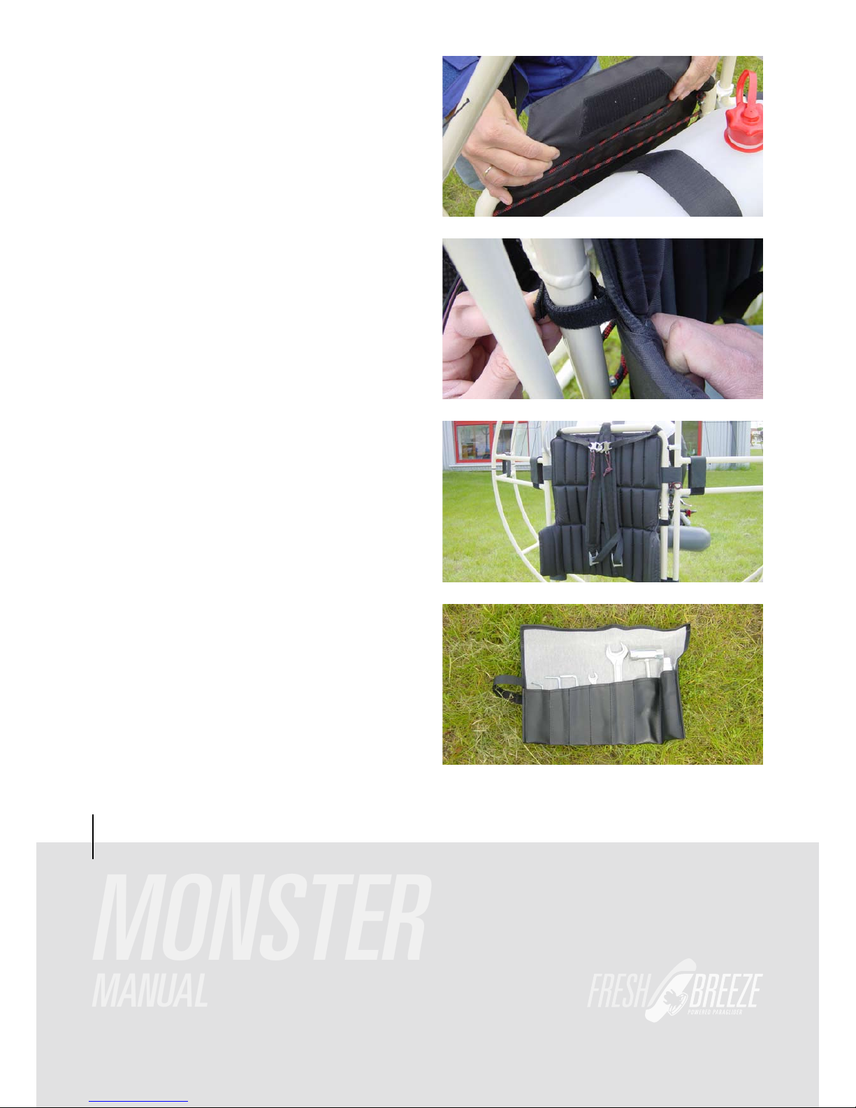
In case that you have a shellform-backstuffing fix it on the left
and rigth side.
Most maintainance you can make by yourself with the
original tools.
Contents:
• Hexagon 4/5/6 mm
• Wrench 8/10/24
• Wrench for sparking-plug and screw driver
• Beltdressing
The Shellform-backstuffing prevent that the motor will turn to
cause from torc.
The backstuffing will fixed also with velcro. The upper and
lower ends from backstuffing turn arround the upper and
lower rope.

6
MONSTER
MANUAL
TECHNICAL DATES
Motor Hirth 310ccm
Type 2-Stroke, 1 Cylinder
Power 20,6 kW
Cooling Air
Starter Manual / E-Starter
Carburettor Bing 84, 32mm
Exhaust Resonator
Propeller 4-Blade
Diameter 122 cm / 48“
Weight 26 Kg / 57 lb
Tank capacity 10 Liter
Max. take off weight 440 lb (200 kg)
NEXT DATES ARE DEPEND FROM:
WEATHER, ALTITUDE, PILOTS WEIGHT, GLIDER AND SIZE AS WELL AS ATMOSPHERIC HUMITY:
Consumtion arround 3l/h
Max. airbone time up to 3 h
RPM 0 - 5800 u/min
Staticthrust up to 176 lb (80 kg)
Climbrate up to 3m/sec.
RESULT FROM THROTTLELEVER-POSITION, FLIGHT-LEVEL, GLIDER AND SIZE AND PILOTSWEIGHT
FOR THE CONSUMTION:
Little throttle less consumtion
Big throttle high consumtion
Low flightlevel less consumtion
High flightlevel high consumtion
Small glider high consumtion high speed
Big glider less consumtion slow speed
Leightweight pilot less consumtion slow speed
Heavyweight pilot high consumtion high speed
Sparc pflug resisted
BR8HS

7
MONSTER
MANUAL
FUEL AND OIL
The motor will delivered with two lid´s. The first is for flight
with a small hole. The second lid is closed for transport. If you
try to fly with the closed one the motor will have a ”in flight
shut down” after a while. It´s will establish inside the tank a
vacuum. The carburettor get fuel from tank through gravity.
The closed lid create inside the fueltank negative or positive
pressure. This can deform the fueltank. Before you start the
engine check the fueltank.
The fuel comes from tank through this filter. Check before
flight.
IMPORTANT INFORMATION
The fuel should have 98 octane or 100 LL. The best oil is
Castrol 2T. Mix 2 % in addition to the fuel.
For the first 10 h mix 4 % in addition to the fuel. In this time
use full throttle very careful.
This picture demonstrate a closed petroltap.
Fasten the velcro around the fuell tank permanent.
Check the gap between fuell tank and exhaust before
each flight.

8
MONSTER
MANUAL
CARBURETTOR AND INTAKESILENCER
The intake silencer ist attached to the cage with 2 bungee
cords (see picture).
In some flyingareas it´s necessary to use such a airfilter. Use
only original parts. Otherwise you risk to loose power.
HOW I CHANGE THE NEEDLE?
Open the lid with the two screws and pull out all parts which
are hanging on the cable.

9
MONSTER
MANUAL
CARBURETTOR AND INTAKESILENCER
Press the spring togehter and loose the cable from slider.
Now you hold slider and lid apart in your hand. The needle is
now loose inside the slider. At our factory we installed the 6L1
in the second position from top.
Here you see succsession from:
Lid/spring/giude piece/needle with ring/slider
WHY DO I HAVE TO ADJUST THE MAIN JET?
Prior to each engine delivery there is a careful and excessive
test run at Fresh Breeze. Usually a 165 main jet is chosen. But
due to different density heights (height of take-off area, temperature, humidity and air pressure) the main jet may have to
be adjustet.
Especially if the take-off area is very high the motor may not
reach its final rpm (about 5600 1/min). Then we recommend a
160 main jet.
HOW TO CHANGE THE MAINJET?
Press the bow back. With the 8 mm wrench screw out the
jet.
ATTENTION:
Do not loose the small red filter.

10
MONSTER
MANUAL
CARBURETTOR AND INTAKESILENCER
Overfloating Carburettor. Fuel comes out of the two small
tubes. The two swimmer regulate the niveau inside the carb.
To reduce the quantity in the carb bend the little tongue careful.
If you hold the carb up side down,the swimmerforc is not parallel to the carburettorcase. If the carb overfloat while using
the motor the forc should look a little bit more upward.
Before you start the cold motor press down the choke. Start
the motor and after a few seconds release the choke.
The big screw regulate the idlerunning.
Turning right-high rpm. Turning left lower rpm.
The idlespeed should round about 2600 1/min.
The smaller screw is responsible for fuelmixture in idle.
Turning right-rich.Turning left-lean.
11
MONSTER
MANUAL
ENGINE
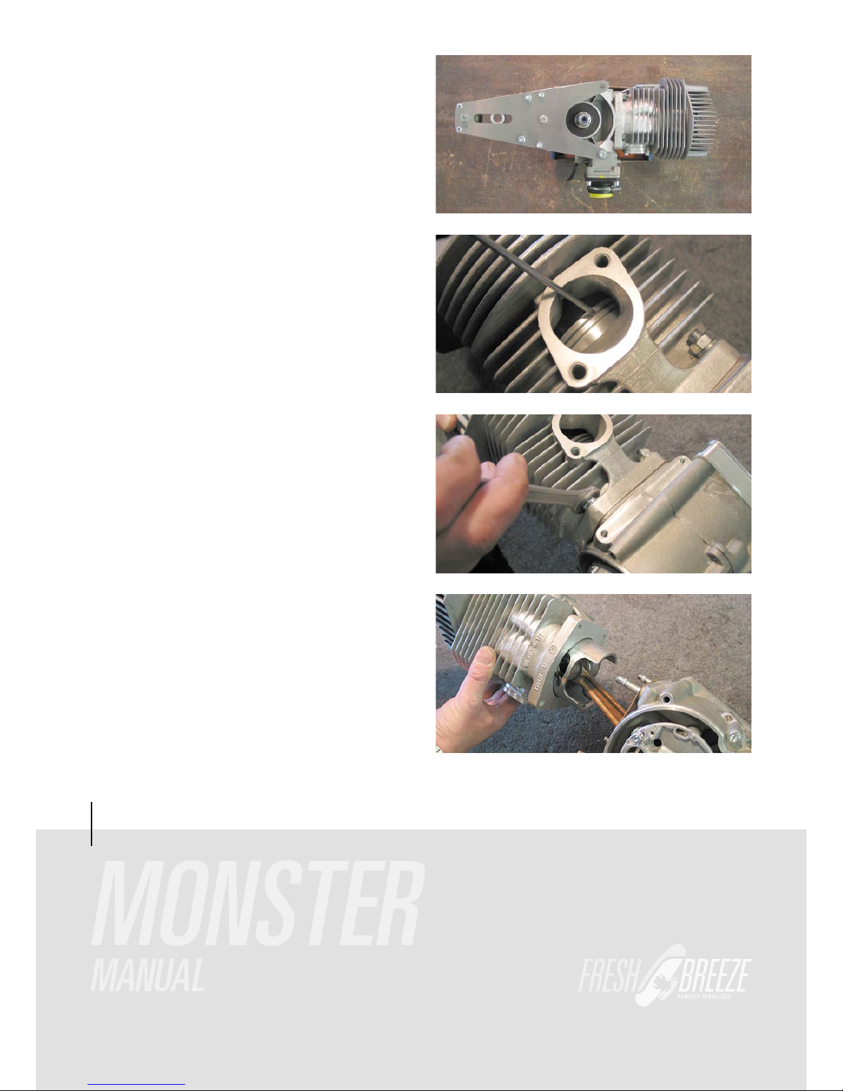
This picture demonstrate the nacked motor with gearboxholder.
In flight the motor will become very hot. The most stressed
airea are the piston and the rings.Remove the exhaust and
have a look to appearenced piston with it´s rings. Test it with
screwdriver.The rings should be loose inside the slot.
HOW TO REPLACE THE PISTON?
At first remove the four nuts from the feed of the cylinder.
Now draw off the cylinder from piston.

12
MONSTER
MANUAL
ENGINE
Before you pull out the gudgeon pin remove the safety rings
on both sides. Than press out the gudgeon pin.
The pistonring can removed by hand.
With a help from a tweezer the safety ring can settled.
To the piston belongs two different rings. The upper ring is
marked with a “O”. This is faced to the top.

13
MONSTER
MANUAL
ENGINE
HOW TO CLEAN THE DECOMPRESSIONHOLE?
After many hour in service time the decompressionhole will
closed with carbon. If you use bad oil it will close earlier. For
cleaning remove the head with the 8 screw (6 mm x 35 mm 14
NM torc).
To reopening the hole use a 3,5mm drill. Bore from top and
from inside the cylinderwall with an angle from 45°.
To seal the head use our spezial high temperature liguidsealing.

14
MONSTER
MANUAL
PULLSTARTER
REPLACMENT OF THE STARTERROPE:
Unsrew the starter-lid, take off the façade plus finger. The
white disc should now be removed by pressing it against the
tension-force.
The white disc can now be taken out of the lid.
The starter-rope can be pulled out of the disc.
To give the starter-rope advanced tension one,place the rolled up into the slot and rotate three times.
15
MONSTER
MANUAL
GEARBOX
The power-transmission of the gears happens via a Poly V
Belt (730 8 PK). The transmission ratio equals 1:2,64. The number of the revolution at full load equals 2200 rpm. The lifespan
of the belt is aprox. 50-100 hrs. Too little tension shorthens the
belt lifspan drastically.
During maintenance check the belt before each flight. The
belt should not be able to be turn over 45° degrees. After the
first flight it is essential to pay special attention to the belt.
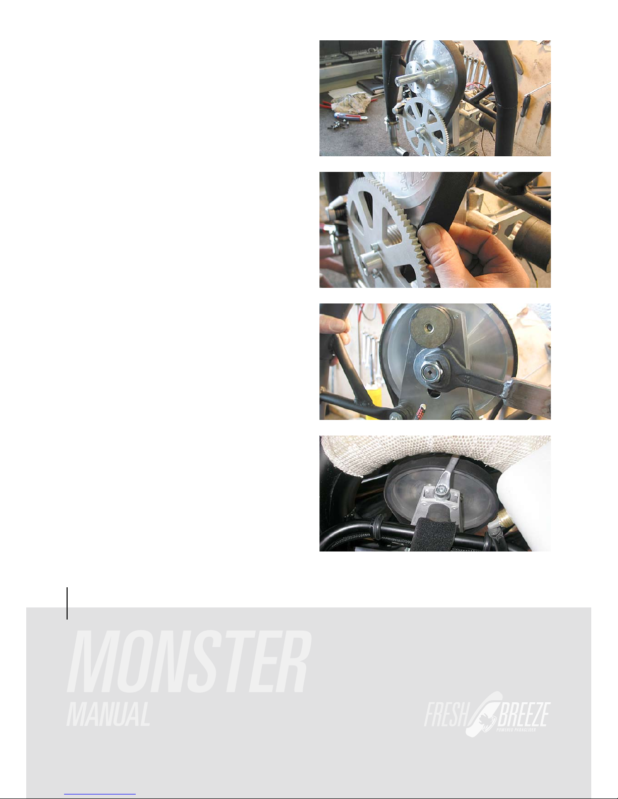
HOW TO TIGHTEN THE BELT:
1. Loosen the central nut (width A/F 24 mm) a little bit
2. Screw the lock nut down and pull thereby the hub upwards.
The belt gets tight. Please make sure that the set screw
M8x80 (width A/F 5 mm) remains totally screwed in, locking
thereby the axle against turning. This set screw must be
secured with medium Loctite (blue).
3. Finally don‘t forget to fasten the central nut again (36 Nm)!

MONSTER
How do I change the belt?
1. If an electronic-starter is fitted at the engine,
the pinion must be dismantled.
2. Central-nut M16x1, 5 (key distance 24 mm)
unscrew a little.
3. Unscrew the 6 mm nut
4. Undoing thread pin with inside hexagon key.
5. As far as, the propeller-hub can be lowered
through releasing the stop nut, now the belt
can be taken of the pulleys.
The new belt can be established now for
tightening the screws we proceed in a
16
MONSTER
MANUAL
GEARBOX
reversed order.

17
MONSTER
MANUAL
GEARBOX
HOW TO REPLACE THE BELT?
1. Loosen the central nut (width A/F 24 mm) a little bit
2. Unscrew the lock nut (upwards). Thereby the hub moves
downwards. The belt gets loose.
3. If the hub remains in the upper position and doesn‘t move:
Unscrew the M8x80 set screw a little bit, this makes it
easier for the hub to move down. Important: Pull this set
screw tight afterwards using medium Loctite (blue). It se
cures the main axle against turning.
4. If the motor is equipped with an electric starter:
Screw a piston lock into the spark plug hole. Loosen the
central screw of the pinion. Loosen the 2 m6x50 screws.
Take the pinion off.
5. Replace the belt. Assemble the pinion again. Remove the
piston block and screw the spark plug into the cylinder
head. Secure the central pininon nut with medium Loctite
(blue).
6. Pull the belt tight as described before.
If the belt makes squeaking noises in spite of the proper tension, then spray twice onto the lower pulley. If the belt is slipping in spite of proper tension, then it needs to be replaced.

18
Gear
Tighten/change the belt from model year january 2009
To loosen the clamp from the
the bolt with allen key 6mm
exenter propellerhup unscrew
To tighten the belt use the
clockwise.
allen key 10 mm and turn
the whole propeller hub
MANUAL
MONSTER

19
MONSTER
MANUAL
PROPELLER
The propeller consist of the two parts which, put together,
measure up to 122 cm in lengh. The weight is ca 900 gram. The
propeller is made of gfk or cfk, which allow for small repairs.
But it is essential that after repair is accomplish, the propeller
gets balanced out again.
The propeller is fixed onto the hub with 6 screws. Tighten the
propeller, use 12 Nm torc.
HOW TO BALANCED OUT THE PROPELLER?
The propeller has to be placed vertically onto the balancingout equip-ment. If turns to one side, then drill a 3,5 mm hole
into the lighter half of the propeller.
Then fill only as much resign into this hole until the propeller
doeas not want to turn to one side only.

MONSTER
MANUAL
PROPELLER
Likewise proceed as above in the horizontal position.
ATTENTION:
AN IMBALLANCED PROPELLER CREATED UNNESSECARY
VIBRATION IN THE ENGINE AND CAN DESTROY MANY OF
IT´S COMPONENTS.
REQUIRED MATERIALS FOR REPAIRS AND BALANCING-OUT!
The propeller balancing-out-resing with hardener,syringe and
a stored shaft for a free turning of the propellerblades
WHAT DO I REQUIRE FOR REPAIRING THE PROPELLER.
Fiberglas-spatula and abrasive paper.
Here now an example when a propellerblade must not be repaired again. If the damage is to large, then repair are dangerous. The repairs sopt has not enough grip and may fall off
whern the propeller turns at high revolution. Danger of accident is thus programmed.

21
MONSTER
MANUAL
ELECTRIC
E-Box
1.
2.
3.
4.
plug
E-starter
altinatorcoil
start switch
ground
engine ground
high ignitioncoil
altinatorcoil
yellow
red
cabelharness
E-starter-motor
+-
stop start
button
plug
Akku 16,8V
11/2008
3 cables
plug
primärcoil
engine ground
Monster / Solo
Wiring diagram „standard“ ignition ( E-Starter )
12 Volt connector

22
MONSTER
MANUAL
ELECTRIC
E-Box
digital
1.
2.
3.
plug
E-starter
start switch
ground
Akku 16,8V
12 Volt
16,8 Volt
plug
1.
2.
PVL CDI Box
plug
engine ground
Startor
PVL ignitioncoil
white
red
E-starter-motor
+-
cabelharness
plug
plug
stop start
button
big plug
5 cables
kill switch
small plug
2 cables
11/2008
„Monster“
engine ground
16,8 V
Wiring diagram „digital“ ignition ( E-Starter )
12 Volt connector
16,8 Volt connector

23
MONSTER
MANUAL
POWER IGNITION SYSTEM
The engine is equiped with a powerful and service free ignition system. It consist of the components: stator, loading-coil
of the ignition, generator coil for the supply of electricity and
rotor. To be able to work on the coils, the following should be
taken care off.
Remove the complete ignitionbox including the lid of the starter. Now the rotor with the starter-pot is visible which is held
into place by it´s central screw.
Once the central screw has been removed, the rotor can then
be pulled off via a puller. Because the rotor has to be in a
specific position to the crankshaft, the rotor with a suspension-disc on the crankshaft is preordained.
To fine-tune the ignition timingpoint one has to loosen the two
security screws of the stator. Turn the stator to the left maximally to the furthest point, now turn ca 2 mm to the right again.
Retighten the security screws. The ignition timingpoint has
now its correct adjustment. When reassembling take special
care of the correct distance of the contact-test that the distance of 0,25 mm is observed and if nessecary readjust.

24
MONSTER
MANUAL
E-STARTER
If the engine is equipped with an e-starter, the power can be
turned on just by pressing the botton on the throttle. The accu
is fixed on the side of the frame and sits in a holster. The accupack consist 14 x 1,2 Volt Nicad cells with max 1700 mAh.
Beside the Accuholster there is a switch with 0 and 1. Set on
0 the engine can´t be left running on the e-starter. Set on 1 the
e-starter is functioning and ready to go. The Accu will only
charged while running and with the switch on at the position
1. Look to the backside of the aluplate you see the controler
with the coolingrips.
Via this plug a voltage can be transmitted. The dynamo has a
limit of max. 24 VA.
The cogwheelplay of the e-starter should be checked after
dismanteling the e-motor and need returning if nessecary.
In order to accomplish this the M4 screws and the security
clamp needs to be loosened. The e-motor can now be adjusted.
The individual theeth of the cog should engage properly. To
little cogwheelplay prohibits the light/smooth running of the
cogs at the start, Is the cogwheel too large, then the theeth
of the pinion will die to early. The cogwheelplay could change
again after tightening, then a re-check is essential.

25
MONSTER
MANUAL
EXHAUST
The engine is equipped with a resonance exhaust which allows for an increase of performance and a decrease of excess noise. The white wrap around tape is made of fiberglass
and gummen up with silicon.
The complete exhaust is suspended flexibly as to prevent vibrational eruptions.
To keep the exhaust flexibly mobile we chose different types
of fixtures. One is a rubber connection on the gear-plate and
two a stress-bearing spring-gasket at the entry and the exit.
After 10 hrs the sealing-rings and their fasten screws needs
to be checked. The screw you have to changes each 25 hrs.

26
MONSTER
MANUAL
THROTTLE RESPECT
The throttle is taken according to the building kind into the
right or left hand. The strap has a variable seize change. Before start the strap should be attracted firmly.
The Respect-thorttle-lever has in each case a switch at the
tube. The one is for the starting the engine.
The other one for killing the engine.
The thottle has also a travelling locking. After reaching the
desired hight of flight, the throttle can be fixed via the clasplever. Since long holt of the throttle is hard in hand, the throttle can be placed in position onto the legs. The hand are now
free for other things.
27
MONSTER
MANUAL
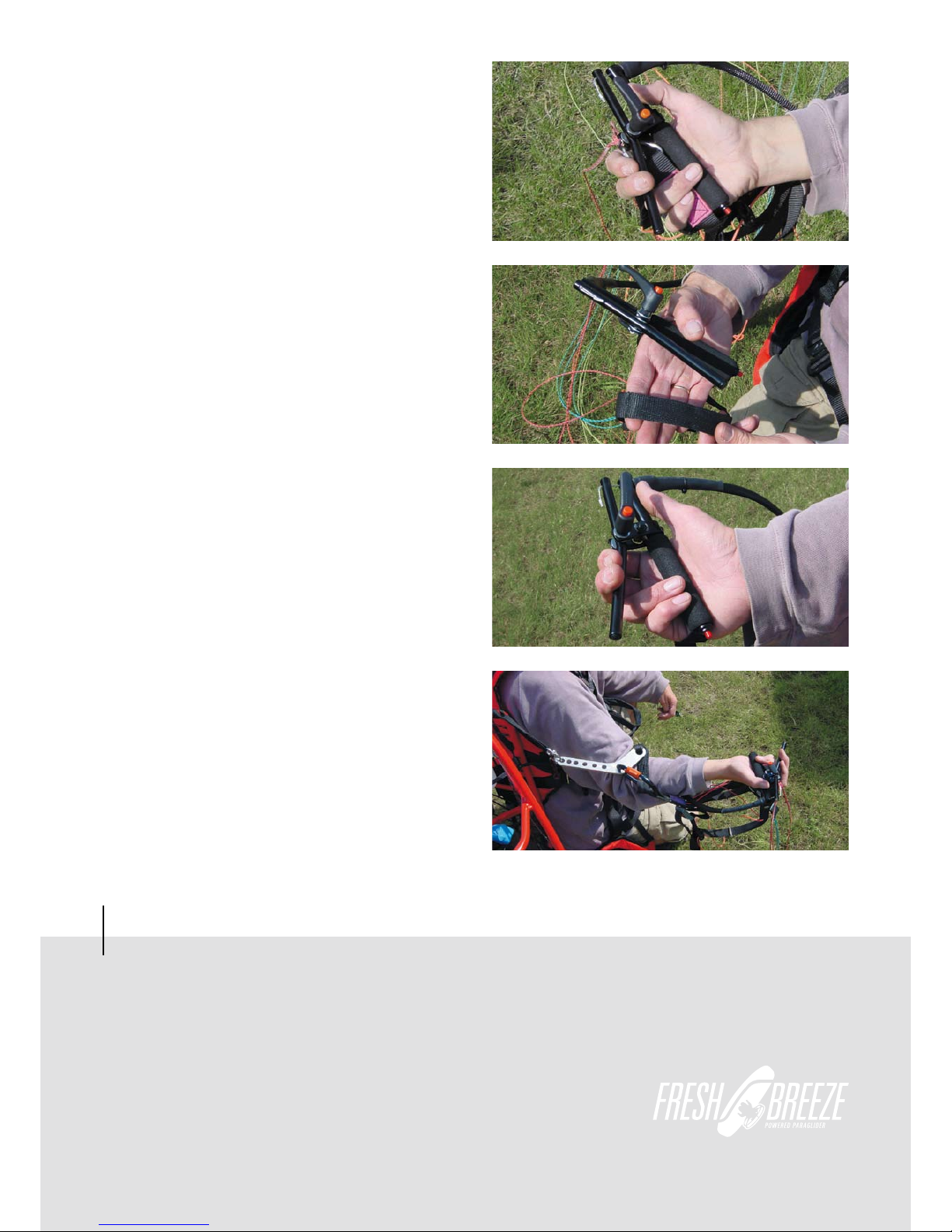
THROTTLE AIRBOSS
The Airboss throttle-lever has also a button for killing the engine and where approbiate about one for starting the engine,
if an electric starter is available.
First the throttle is taken into the hand ...
... after that the steering line and at last the A-riser are grasped.
This picture clarifies the handling of the riser and the throttle
during the start.

28
MONSTER
MANUAL
HARNESS
This harness is specially constructed for motoring enterprises. Throughout the usage of the maschine, ensure that no
lose ends are able to get into the propellerblades. The suspension for pilot can be permanently in the snap links.
The harness is secured via 3 springlocks; tow legs spring and
one breast spring lock. It has two adjsutments possibilities.
One there are the buckles which are fastenen onto the front
of the seat. At the start these should be pulled on lightly, as to
make the climbing into the harness easier at the lift-off. Before landing it is advisable to lower the seat fully, to enable a
maximal favourable touch-down position. The leg loop does
not need to be pulled too tightly.
The harness has also two pockets, which are easily reached
at flight.
All other adjustment options are regulated while flying. Are
the straps pulled rigth and left, then one sits up straight, are
they loose a slight back prone position can be adopted.

29
MONSTER
MANUAL
HARNESS
Now one kneels in front of the engines and pulls the carrying
straps over the shoulders.
Thereafter the pilotsuspension has to be hang into the dropping device of the engine. Usally the hind most hole is used
for this. The dropping device should be activated at pending
danger, for example at a water landing, fire at high altitude or
a tree touchdown.
The activation occurs when the two strings of the dropping
device are pulled outwards. Because the engine is now not
hanging over the suspension of the chute anymore, the pilot
will be in a brought into a strong reclining position. Thus the
engine can now slide easily over the shoulders. The landing
proceeds from now on without the engine.

30
MONSTER
MANUAL
HARNESS
Now one get up with the whole engine and goes to the glider.
The glider will then be hang into the springlocks for the pilots
suspension.
After all has been done, the throttle and the break-loop had to
be taken into the hand. The engine will now be started and the
starting run can begin.
RESCUE SUSPENSION
The picture shows an example of how to fasten the recuedevice using the V-line. The rescuedevice should be connect
with the pilot suspension using the V-line. So it´s an optimal
landing position in case of a possible release. The rescuedevice should not be hung in the harness using the spring
hooks,because of supine in rescue release.

31
MONSTER
MANUAL
WINGMAN CB
... and secure with the quickpins.
At next insert the cb bars into the frame ...
This picture show´s the attached harness.
HOW TO FASTEN THE HARNESS WINGMAN CB
Attach the harness with the velcro on the frame.

32
MONSTER
MANUAL
WINGMAN CB
The lateral and adjustable belt´s from the harness
goes outside the cb bar´s.
The rear pilotsuspension must fixed in the metal-eyelet.
The rear pilotsuspension is adjsutable. For basic position
pull the loop until the carabiner. Heavy pilots should open
and light weight pilots should close the belt.
Here you must fix the carringsstraps from harness
to the frame.

33
MONSTER
MANUAL
WINGMAN CB
The glider should fixed into this carabiner.

New features at the Wingman Cbi (integrated rescue)
At the Wingman Cbi the rescue is intergated.
As you can see the Vcord runs
around the pilot from behind.
At the Wingman Cbi the rescue is intergated.
The V cord is led to the carabines
from behind and fixed with the
Velcro loops.
The neoprene outer container
34
holds the rescue system,
which is fitted with a Zipper onto the wingman.
The V cord is runs behind the Pilot

Wingman CBi
The carrying belts go
through the back
of the wingman.
MONSTER
HANDBUCH
WINGMAN CBi
35

36
MONSTER
MANUAL
THE FOLLOWING POINTS SHOULD BE CARRIED OUT BEFORE EVERY START!
01. CHECK ALL PARTS FOR TIGHTNESS, CHECK ALL FASTENERS!
02. VISUAL INSPECTION OF CAGE AND FRAME FOR FRACTURES!
03. PROPELLER HUB WITHOUT CLEARANCE?
04. EXHAUST SPRINGS OK?
05. EXAMINATION OF EXHAUST RUBBER ELEMENTS!
06. PETROL FILTER NOT SOILED?
07. MOTOR, CARBURETTOR AND TANK LEAK-PROOF?
08. SUFFICIENT SUPPLY OF PETROL?
09. PILOT SUSPENSION UNDAMAGED?
10. CANOPY UNDAMAGED?
11. GAS LEVER POSITION?
12. TRAVELLING LOCK RELEASED?
13. FUEL TAP OPEN?
14. VENTILATED TANK LID ON TANK?
15. PROPELLER CLEAR – START MOTOR!
16. CARRY OUT A TEST AT FULL THROTTLE!
17. TEST THE OFF-SWITCH FUNCTION
18. PILOT PROPERLY HOOKED IN?
19. WIND DIRECTION AND WIND FORCE?
EVERYTHING O.K.? CLEAR FOR TAKE-OFF!
PRE-FLIGHT CHECK
20.
TAKE-OFF STRETCH CLEAR?
FUEL TANK IS FIXED AND THE GAP BETWEEN EXHAUST-FUEL TANK ASSURED
21.

37
MONSTER
MANUAL
CHECKLIST
CHECK BEFORE EACH FLIGHT
ü
CAGE SECURED ON THE FRAME
ü
CAGE IN GOOD SHAPE
ü
PROPELLER-CLEARANCE
ü
PROPELLER WITHOUT FREE SPACE
ü
PROPELLER WITHOUT DAMAGE
ü
BELT O.K.
ü
TENSION O.K.
ü
KILLSWITCH O.K.
ü
FUEL MIN.98 OCTANE OR HIGHER
ü
FUEL TANK LEAKY
ü
PILOT SUSPENSION AND STRAP WITHOUT STRESSMARKS
ü
SPARKING PLUG AND WIRE WELL FIXED
ü
TANK-LID WITH SMALL HOLE ON THE TANK
ü
PROOF GLIDER,LINES AND RISER FOR STRESSMARKS OR DAMAGE´S.
ü
INTAKESILENCER AND IT´S FIRMNESS
ü
FULL RPM MIN 5600 1/MIN
ü
PROOF ALL RUBBERJOINTS
CHECK ALL 10 HOURS
ü
FUEL FILTER
ü
CLEAN THE CARBCHAMBER
ü
BELT
ü
EXHAUST INCL. THE SELAINGRINGS AND THE SCREWS.
ü
ALL CONNECTION FROM THE WIRES
ü
CHECK ALL 10 HOURS
ü
REPLACE THE BELT
ü
METAL-WIRE FROM THROTTLE
ü
REPLACE THE SPARKING PLUG AND THE CONNECTOR
ü
REPLACE ALL RUBBERJOINT FROM EXHAUSTSYSTEM
ü
REPLACE THE SEALINGRINGS AND THE SCREWS
ü
CHECK ALL SCREWS
ü
PROOF CARRINGSTRAPS FOR PRACTICAL
ü
LEAKY FROM WHOLE SYSTEM

38
MONSTER
MANUAL
CHECK ALL 50 HOURS
ü
PROPELLERBALANCE
ü
CHANGE NEEDLE AND NEEDLEJET
ü
REPLACE STARTERFINGER
ü
REPLACE SPIRAL-INTAKETUBE
CHECK ALL 100 HOURS
ü
CLEANING THE DECOMPRESSIONHOLE INSIDE THE CYLINDER
ü
PISTONRINGS
ü
REPLACE CARABINER FROM PILOTSUSPENSION
ü
REPLACE CARB-SLIDER
ü
REPLACE BEARING FROM PROPELLERHUB
ü
CHECK BEARINGS FROM CRANKSHAFT
CHECK ALL 300 HOURS
ü
THE ENGINE AND HIS COMPONENTS SHOULD SEND TO THE MANUFACTURING FOR GENERAL MAINTENANCE
GLIDER
THE GLIDER SHOULD BE CHECKED ALL 2 YEARS. SEND TO THE MANUFACTURER
MOTOR
THE ENGINE SHOULD BE CHECKED EACH YEAR ALIKE HOW MUCH HOURS IT´S USED
WITHOUT THESE CHECK´S NO WARRENTY OR OTHER CLAIMS!
PLEASE USE ONLY FRESH BREEZE GENUINE SPARPARTS.THIS WILL TAKEN POSSESSION ALL SAFETY AND
STIFFNESS WHICH IS REQUIERED FROM DULV.
CHECKLIST
!
!
!
Unexperienced pilot´s should have minimum 100kg (220 lbs).
Otherwise you risk a stall or twist in while of full throttle
Change the carabiner from the pilotsuspension each 100 h
ü

39
MONSTER
MANUAL
SAFETY ADVICE
BE SURE TO FOLLOW THIS SAFETY ADVICE EVERY TIME YOU USE FRESH BREEZE MOTORS !
• USE YOUR ENGINE CAREFULLY. DISREGARDING ANY SAFETY ADVICES AND
INCAUTIOUS BEHAVIOUR MAY LEAD TO SERIOUS INJURIES.
• NEVER COME CLOSE OR GRAP INTO THE SPINNING PROPELLER. HIGH RISK OF SEROIUS INJURIES.
• THE ENGINE MAY NOT BE STARTED WHEN IT IS STANDING ON THE GROUND. HIGH RISK OF SERIOUS INJURIES.
• NEVER TOUCH HOT PARTS (ENGINE, EXHAUST). HIGH RISK OF BURNING.

40
MONSTER
Coolant and bleed
How to fill up with Coolant and bleed the cooling system for the Liquid Cooled Monster:
In the first picture you will see the bleed tap.
In the second picture you will see the lid and tube to refill
1. Open the bleed tap.
2. Fill up the coolant until it comes out of the bleed tap.
Water temperature in flight should be between
and then close the bleed tap.
IMPORTANT: Turn the propeller for two rotations to
the coolant. A thermostatic cap is fitted which
opens at about 95-100°C or pressure of 0.9 bar.
be sure the air vents out of the coolant pump
There will be about 10cm of air in the filler tube.
MANUAL
68-85° Celsius (155° - 185° F)
 Loading...