

Fresenius Kabi AGILIA SP MC WIFI CA Instructions For Use Manual
AGILIA SP MC WIFI CA
Syringe Infusion Pump
Applicable to software version 2.2
Instructions For Use
For Use in Healthcare Facilities
(Disponible en Français sur demande)

Symbol Descriptions
IP22
Warning
(Refer to the Instructions for Use)
Refer to the Instructions for Use
Product reference / part number
Product serial number
IN: Input terminal - connector Fragile, handle with care
OUT: Output terminal - connector This way up
Electrical fuses Keep away from rain
Alternating Current (AC) Temperature limitation
Direct Current (DC) Humidity limitation
Index of protection against solid
foreign objects (> 12.5 mm) and
dripping liquids
Not for use in residential areas
Name and address of the
manufacturer / Date of manufacture
Name and address of the
manufacturing facility
Protection against electric shock:
class II
Non-ionizing electromagnetic
radiation
Atmospheric pressure limitation
General symbol for recyclable
material
Part included in a recycling process Eco packaging symbol
Protection against leakage current;
defibrillation-proof type CF applied
part
CSAUS mark
C
Warning of a potential hazard that
could result in serious personal
injury and/or product damage if the
written instructions are not followed.
Caution: Federal law restricts this
device to sale by or on the order of a
physician
Recommendations to be followed.
14209-2_master_ifu_agilia_sp_mc_eng_CA
(See 21 CFR 801.109(b)(1))

Table of Contents
1 INTRODUCTION 9
1.1 S
1.2 I
1.3 P
1.4 I
1.5 I
1.6 I
1.7 C
1.8 U
COPE ...................................................................................................9
NTENDED USE........................................................................................9
RINCIPLES OF OPERATION.....................................................................9
NTENDED PRODUCTS TO BE INFUSED....................................................10
NTENDED USERS..................................................................................10
NTENDED PATIENTS .............................................................................11
ONTRAINDICATIONS.............................................................................12
SE ENVIRONMENT...............................................................................12
2 DESCRIPTION 13
2.1 F
2.2 B
2.3 B
2.4 K
2.5 D
RONT VIEW.........................................................................................13
OTTOM VIEW (DEVICE IDENTIFICATION LABEL) .....................................13
ACK VIEW...........................................................................................14
EYPAD................................................................................................15
ISPLAY AND SYMBOLS.........................................................................17
2.5.1 Infusion Status.................................................................................... 17
2.5.2 Screen Options................................................................................... 17
2.5.3 Navigation Buttons ............................................................................. 17
2.5.4 Alarms and Safety Features............................................................... 18
2.5.5 Infusion Features................................................................................ 18
2.5.6 Data Communication.......................................................................... 18
2.6 PACKAGING ..........................................................................................19
3 FUNDAMENTALS 20
3.1 P
3.2 D
3.3 D
ROFILES .............................................................................................20
RUG LIBRARIES...................................................................................21
RUGS .................................................................................................21
3.3.1 Infusion Rates .................................................................................... 21
3.3.2 Drug X (mL/h)..................................................................................... 21
3.3.3 Hard Limits and Soft Limits ................................................................ 22
3.3.4 Infusion Modes................................................................................... 22
3.4 DATA SET .............................................................................................22
3

4 INSTALLATION 23
4.1 T
4.2 U
4.3 A
YPES OF INSTALLATIONS .....................................................................23
SING THE ROTATING POLE CLAMP.......................................................24
TTACHING THE PUMP(S) ......................................................................25
4.3.1 Attaching to a Pole ............................................................................. 25
4.3.2 Attaching to a Rail .............................................................................. 25
4.3.3 Using on a Flat Table ......................................................................... 26
4.3.4 Attaching Two Pumps Together......................................................... 26
5 GETTING STARTED 27
5.1 F
5.2 U
5.3 P
5.4 I
5.5 P
LOWCHART .........................................................................................27
SING THE PUMP FOR THE FIRST TIME..................................................28
OWERING ON ......................................................................................28
NSTALLING A SYRINGE..........................................................................30
UMP HEIGHT.......................................................................................31
6 OPERATION 32
6.1 F
6.2 S
6.3 S
6.4 S
6.5 P
LOWCHART .........................................................................................32
ELECTING A PROFILE ..........................................................................33
ELECTING A SYRINGE ..........................................................................33
ELECTING A DRUG ..............................................................................34
ROGRAMMING AN INFUSION .................................................................35
6.5.1 Programming an Infusion by Flow Rate ............................................. 35
6.5.2 Programming an Infusion by Dose Rate ............................................ 35
6.5.3 Programming Beyond Soft Limits....................................................... 39
6.6 STARTING AN INFUSION .........................................................................41
6.7 M
6.8 F
ONITORING AN INFUSION.....................................................................42
UNCTIONS DURING INFUSION ...............................................................44
6.8.1 Stop.................................................................................................... 44
6.8.2 Rate Titration...................................................................................... 44
6.8.3 Administering a Bolus......................................................................... 44
6.9 COMPLETING AN INFUSION ....................................................................47
6.9.1 Near End of Infusion Alert ............................................................. 47
6.9.2 End of Infusion ................................................................................... 48
6.9.3 Powering off ....................................................................................... 48
6.10 INFUSION MODES ..................................................................................48
6.10.1 Simple Rate ........................................................................................ 48
4

6.10.2 Volume/Time & Dose/Time ................................................................ 49
6.10.3 Volume Limit....................................................................................... 50
6.11 OTHER FUNCTIONS ...............................................................................51
6.11.1 Priming the Syringe and the Extension Set........................................ 51
6.11.2 Pre-programming the Pump ............................................................... 53
7 MENUS 54
7.1 O
7.2 P
7.3 O
7.4 K
7.5 B
7.6 V
7.7 P
7.8 P
7.9 P
7.10 D
7.11 V
7.12 V
7.13 A
7.14 V
7.15 V
7.16 V
7.17 S
7.18 V
7.19 D
7.20 M
7.21 L
7.22 C
7.23 D
VERVIEW ............................................................................................54
ROFILE ...............................................................................................55
CCLUSION PRESSURE .........................................................................56
EYPAD LOCK STATUS..........................................................................58
ATTERY LIFE.......................................................................................60
OLUME INFUSED / DOSE INFUSED ........................................................61
AUSE..................................................................................................61
ROGRAMMED BOLUS ...........................................................................62
ATIENT ...............................................................................................63
AY/NIGHT MODE.................................................................................63
OLUME/TIME & DOSE/TIME..................................................................65
OLUME LIMIT.......................................................................................66
LARM VOLUME ....................................................................................66
OLUME-DOSE HISTORY .......................................................................67
IEW FLOW RATE HISTORY ...................................................................68
IEW PRESSURE HISTORY ....................................................................69
YRINGE...............................................................................................70
IEW EVENT LOG..................................................................................70
ATE /TIME .........................................................................................71
AINTENANCE ......................................................................................72
IBRARY INFORMATION ..........................................................................73
LINICAL INFORMATION .........................................................................74
ATA SET .............................................................................................75
8OPTIONS 76
8.1 C
8.2 O
8.3 P
OMMANDS ..........................................................................................76
PTION DESCRIPTIONS .........................................................................76
UMP SETTINGS ...................................................................................77
5

9 DATA COMMUNICATION 78
9.1 O
9.2 C
9.3 C
9.4 D
VERVIEW ............................................................................................78
OMMUNICATION VIA AGILIA CABLES .....................................................78
OMMUNICATION VIA WI-FI ...................................................................79
ATA SET UPLOAD ...............................................................................79
10 USER TEST 80
11 ALARMS AND SAFETY FEATURES 81
11.1 I
11.2 A
11.3 G
11.4 L
NTRODUCTION......................................................................................81
LARM DESCRIPTIONS ..........................................................................81
ENERAL REMARKS ..............................................................................82
IST OF ALARMS ...................................................................................82
12 SYRINGES 87
12.1 S
12.2 P
12.3 O
12.4 G
YRINGE LIST .......................................................................................87
REPARING A SYRINGE .........................................................................87
PERATIONS FOR SYRINGES .................................................................89
RAVITY INFUSION IN PARALLEL WITH A PUMP .......................................90
13 DEVICE STORAGE 91
13.1 P
13.2 S
13.3 P
13.4 U
RECAUTIONS FOR STORAGE ................................................................91
TORAGE AND TRANSPORT CONDITIONS................................................91
REPARING THE DEVICE FOR STORAGE .................................................91
SING THE DEVICE AFTER STORAGE .....................................................91
14 SPECIFICATIONS 92
14.1 E
14.2 F
14.3 V
14.4 D
14.5 I
14.6 C
14.7 P
SSENTIAL FEATURES...........................................................................92
LOW RATE ..........................................................................................92
OLUME TO BE INFUSED (VTBI) ...........................................................93
OSE TO BE INFUSED (DTBI) ...............................................................93
NFUSION TIME......................................................................................93
ONCENTRATION ..................................................................................94
ATIENT DATA ......................................................................................94
6

14.8 P
14.9 A
14.10 U
RESSURE MANAGEMENT .....................................................................94
CCURACY ...........................................................................................95
NITS AND CONVERSION RULES............................................................97
15 CLEANING AND DISINFECTING 99
15.1 W
15.2 R
15.3 I
HEN TO CLEAN AND DISINFECT THE PUMP ..........................................99
ECOMMENDED AND PROHIBITED AGENTS.............................................99
NSTRUCTIONS FOR CLEANING AND DISINFECTING ................................100
16 POWER MANAGEMENT 103
16.1 AC P
16.2 B
16.3 B
OWER SUPPLY PRECAUTIONS......................................................103
ATTERY PRECAUTIONS ......................................................................103
ATTERY OPERATING MODE ...............................................................104
17 TECHNICAL CHARACTERISTICS 105
17.1 P
17.2 B
17.3 P
17.4 C
17.5 I
17.6 S
17.7 C
17.8 D
17.9 T
OWER SUPPLY..................................................................................105
ATTERY ............................................................................................105
OWER CONSUMPTION........................................................................105
OMMUNICATION PORT .......................................................................105
NFRARED COMMUNICATION.................................................................106
OUND LEVELS ...................................................................................106
OMPLIANCE ......................................................................................107
IMENSIONS AND WEIGHT ...................................................................107
RUMPET AND START-UP CURVES .......................................................107
18 WI-FI 110
18.1 G
18.2 S
ENERAL INFORMATION ......................................................................110
PECIFICATIONS .................................................................................110
7

19 TROUBLESHOOTING 112
20 RECYCLING 113
21 WARRANTY 114
21.1 G
21.2 L
21.3 W
ENERAL WARRANTY CONDITIONS ......................................................114
IMITED WARRANTY ............................................................................114
ARRANTY CONDITIONS FOR ACCESSORIES ........................................114
22 GUIDANCE AND MANUFACTURER'S DECLARATION ON EMC 115
22.1 E
22.2 E
22.3 EMC
22.4 E
LECTROMAGNETIC COMPATIBILITY ....................................................115
LECTROSTATIC DISCHARGE (ESD) AND PRECAUTIONS TO BE TAKEN .115
AND ESSENTIAL PERFORMANCE..................................................116
LECTROMAGNETIC COMPATIBILITY AND INTERFERENCE GUIDANCE ....116
23 SERVICING 118
23.1 I
23.2 M
23.3 Q
NFORMATION ON DEVICE SERVICING...................................................118
AINTENANCE REQUIREMENTS............................................................118
UALITY CONTROL .............................................................................118
24 AGILIA CONNECT INFUSION SYSTEM COMPATIBILITY 119
24.1 D
24.2 A
24.3 R
24.4 S
ATA MANAGEMENT CABLES...............................................................119
SSOCIATED SOFTWARE .....................................................................119
ACKS AND ACCESSORIES ..................................................................120
YRINGES...........................................................................................120
25 GLOSSARY OF TERMS 122
APPENDIX: FACTORY CONFIGURATION 124
INDEX 125
8

1 Introduction
1.1 Scope
These Instructions for Use (IFU) are applicable to the Agilia SP MC WiFi. This
device is referred to throughout this manual as the "Agilia SP MC" or "Agilia
pump".
The user must adhere to the instructions specified in this IFU. Failure to adhere to
these instructions may result in damage to the equipment, injury to patients or
injury to users.
Warning
Check that this IFU is applicable to the current software version of the
device.
The software version of the device is displayed on the start-up
screen.
The software version described in this IFU is displayed in the
Release Notes, page 127.
1.2 Intended Use
The Agilia SP Infusion System is intended for use on adults, pediatrics, and
neonates for the intermittent or continuous delivery of parenteral fluids,
medications, blood and blood derivatives through clinically accepted routes of
administration such as intravenous, intra-arterial and subcutaneous routes.
It is intended for use by trained healthcare professionals in healthcare facilities.
1.3 Principles of Operation
Agilia SP MC is a programmable electronic medical system dedicated to
administering a pre-determined volume of a syringe at a programmed rate. This
syringe pump ensures fluid delivery, by pushing the syringe plunger and
advancing the liquid to the patient through an extension set equipped with a
female Luer lock (applied part).
Agilia SP MC can be used standalone or mounted on the Agilia Link rack.
Agilia SP MC is a transportable and reusable device that can be used everyday.
The size of a syringe can be minimum of 5 mL and maximum of 60 mL. For
comprehensive list, see Section 24.4, page 120.
Agilia SP MC is intended for use on only one patient at a time. It can be reused
indefinitely on multiple patients throughout its lifetime.
9

1.4 Intended Products to be Infused
The pump administers products through clinically accepted routes. These
products include but are not limited to the following:
Intended Products
Standard solutions
Parenteral Fluids
Medication
Transfusion
When using Agilia SP MC to infuse critical medications in healthcare facilities,
ensure that adequate monitoring is provided, and that backup pumps and syringes
are available for immediate use.
Only use Agilia SP MC for the infusion of fluids that are intended for infusion
pumps.
Colloids
Parenteral nutrition
Diluted drugs
Antibiotics
Chemotherapy
Catecholamines
Short acting drugs
Anesthesia drugs
Blood
Red blood cells
Platelets
Plasma
Albumin
1.5 Intended Users
The pump must only be used by qualified and trained healthcare professionals
including but not limited to: nurses (primary users), physicians, nurse practitioners
and physician assistants.
Typical initial training duration: 1 hour.
It is recommended that users attend a refresher training session of about
20 minutes every year.
For training, contact your Fresenius Kabi sales representative.
10

1.6 Intended Patients
Agilia SP MC is intended to be used according to healthcare facilities protocols on
patients with the following characteristics:
Patient Characteristics
Sex
Age
Adults (including elderly)
Weight
Male
Female
Neonates
Pediatrics
0.25 kg to 350 kg
Body Surface Area
Note: 1 kg = 2.2 lb
0.05 m² to 4.5 m²
When using the pump with specific patients easily affected by light and noise like
neonates, make sure to:
Switch to night mode
Set the alarm volume to the minimum level
Warning
Specific attention for infusing high risk and life sustaining medication
therapies : use the smallest compatible syringe size necessary to deliver
the fluid or medication; this is especially important when infusing high
risk or life-sustaining medications at low infusion rates (e.g., less than
5 mL per hour, and especially flow rates less than 0.5 mL per hour).
Using a larger syringe when infusing at low rates can lead to inadequate
syringe pump performance including delivery inaccuracies, delay of
therapy, and delayed generation of occlusion alarms. This is due to the
increased friction and compliance of the syringe plunger head with larger
syringes.
11

1.7 Contraindications
Do not modify the pump (except in the case of operations recommended
by Fresenius Kabi).
Do not use the pump with the following fluids:
- Flammable liquids
- Fluids not suitable for infusion
Do not use the pump in the following environments:
- Explosive or flammable environments
- High humidity environments (shower, bath, etc.)
- Ultrasonic environments
- Magnetic Resonance Imaging (MRI)
- Hyperbaric chamber
Do not use the pump for the following purposes:
- Infusion in association with a dialyser or ECMO
- Enteral nutrition
- Epidural use
Do not allow the pump to come in direct contact with the patient's body.
While the pump is infusing a patient, do not connect a computer installed
with Agilia Partner software to perform technical operations.
1.8 Use Environment
Agilia SP MC is intended for use in healthcare facilities, under the supervision of
trained healthcare personnel.
The pump must be used in the following operational conditions to ensure proper
performance:
Operating temperature range:
41 °F (5 °C) to 104 °F (40 °C)
Operating pressure range:
700 hPa (525 mmHg / 10.15 PSI) to 1060 hPa (795 mmHg / 15.37 PSI)
Operating humidity range:
20 % to 90 % with no condensation
Altitude:
Up to 9842.52 ft (3000 m) above sea-level
Warning
The functionality of the pump can be affected by pressure variations,
mechanical shocks, heat ignition sources, and so on.
Information
For more information on using the device in specific conditions, contact
your Fresenius Kabi sales representative.
12
2 Description
3 5
6
2
1
4
1
1
4
1
235
3
3
6
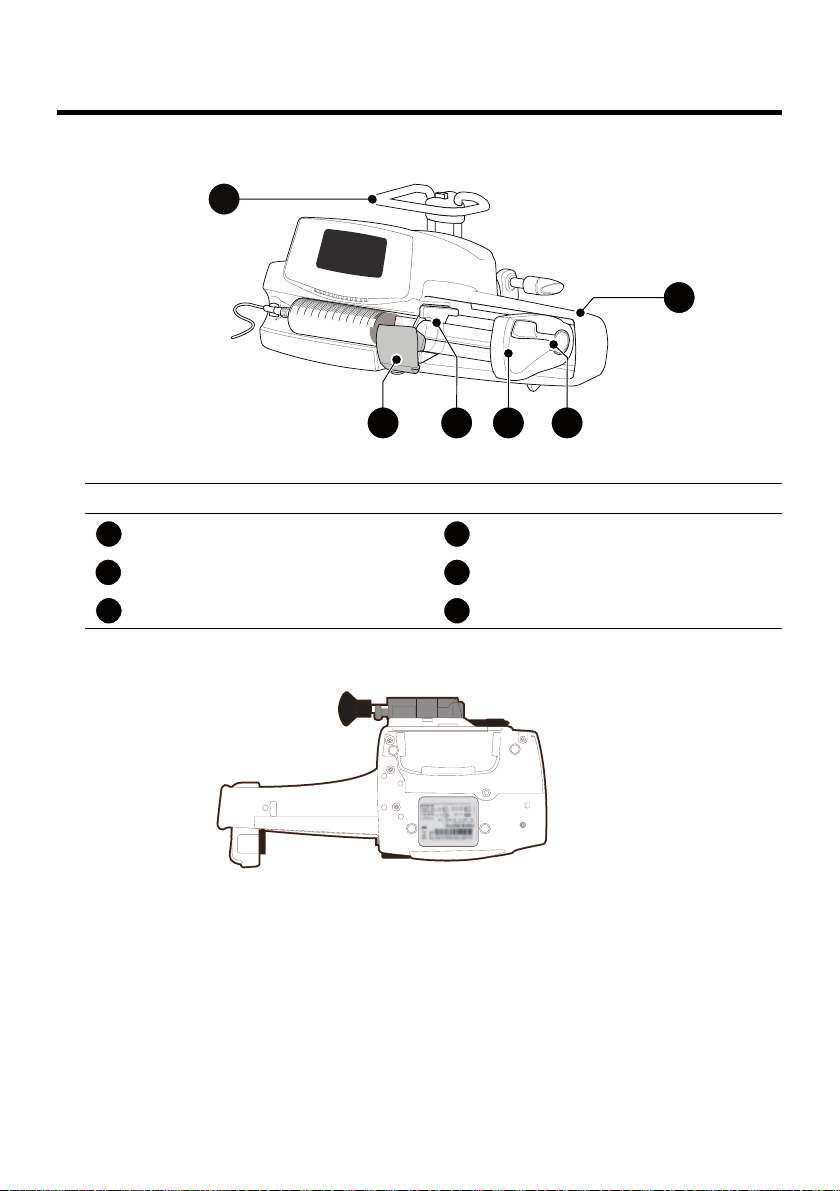
2.1 Front View
Figure 2.1: Front View
Legend
Handle Plunger Driver
Syringe Barrel Clasp Disengagement Lever
Syringe Flange Cradle Syringe Guard
2.2 Bottom View (Device Identification Label)
The UDI (Unique Device Identifier) is represented in AIDC (Automatic
Identification and Data Capture) and readable text:
(01) Product Identifier GTIN
(21) Product Serial Number
(11) Date of Manufacture
(240) Product Reference
For more information on device identification label symbols, see Symbol
Descriptions, page 2.
13
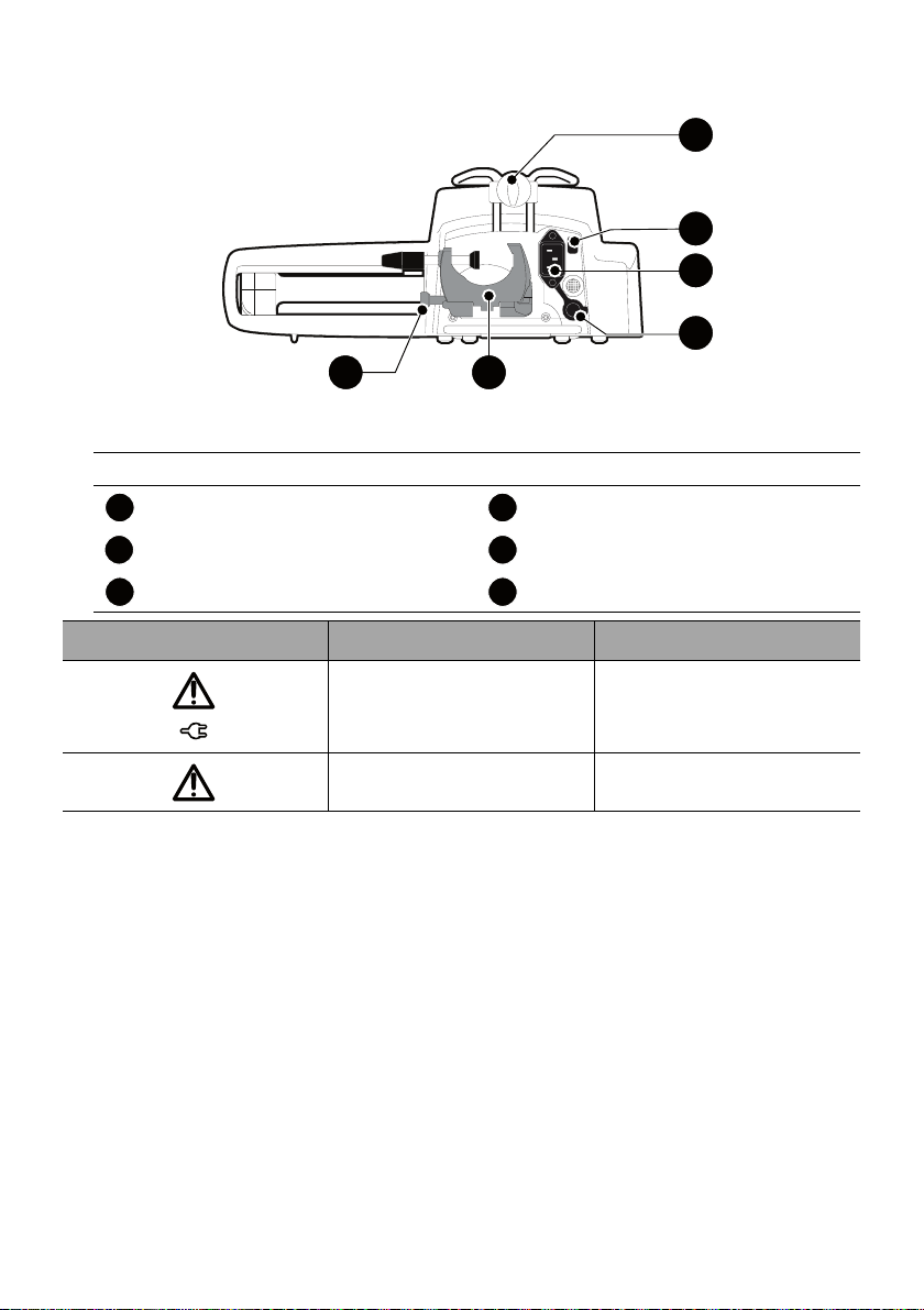
2.3 Back View
6
4
3
5
2
1
1
1
4
1
235
3
3
6
Legend
Release Button Power Cord Inlet
Rotating Pole Clamp Infrared Cell
RS232 Communication Port Attachment Lock Knob
Symbol Location Description
Figure 2.2: Back View
Near Power Cord Inlet
Warning
See section 17, page 105.
Near RS232
Communication Port
Warning
See section 9, page 78.
14
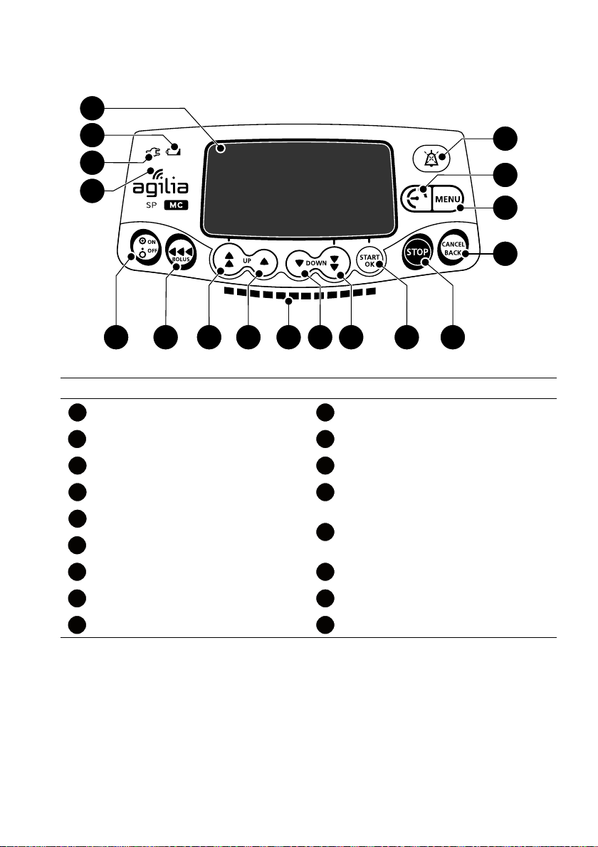
2.4 Keypad
9
15
14
17
16
1312118 10765
1
2
3
4
1
3
710
1
2311
3312
4313
5
3
14
3
6
373
15
383
16
3793
17
2.4.1 Keypad Description
Legend
Screen Decrement
Battery Charge Status Indicator Fast Decrement
Power Supply Indicator Confirm Value / Move to Next Field
Figure 2.3: Keypad
Wi-Fi Symbol Stop
On / Off
Bolus / Prime
Fast Increment Menu
Increment Pressure Menu
Infusion Indicator Lights Alarm Silence
Cancel Value / Move Back to Previous
Field
15
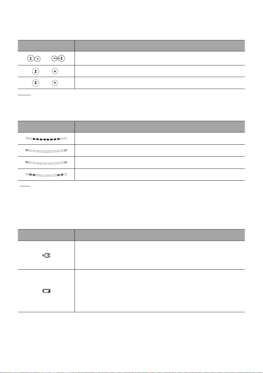
2.4.2 Keypad Details
2.4.2.1 Selection Keys
Key Description
Arrow Keys
Keys for selecting volume, time, flow rate and other values.
+
Fast Access to Maximum Value or Top of a List
+
Note:
Fast Access to Minimum Value or Bottom of a List
Pressing and holding any of the arrow keys results in faster increment or decrement.
2.4.2.2 Infusion Indicator Lights
Indicator Description
Infusion in Progress (flashing green)
Low-Priority Alarm (constant yellow)
Note
Medium-Priority Alarm
High-Priority Alarm (flashing red)
:
(flashing yellow)
Infusion indicator lights provide information about the infusion: in progress, or with a low, medium
or high-priority alarm.
Green indicator lights will continuously flash from right to left while the infusion is running.
The frequency of flashing varies according to flow rate.
2.4.2.3 Status Indicators
Indicator Description
Power Supply Indicator
When the device is attached to an active power supply, the indicator light is
a constant green. If the pump is not connected to the AC power, it does not
light up.
Battery Charge Status Indicator
When the device is attached to an active power supply, the indicator light
provides information about battery charge status:
If the indicator is blinking, the battery is being charged.
If the indicator is lit permanently, the battery is fully charged.
If the pump is not connected to the AC power, it does not light up.
16
2.5 Display and Symbols
start
OK
enter
New ?
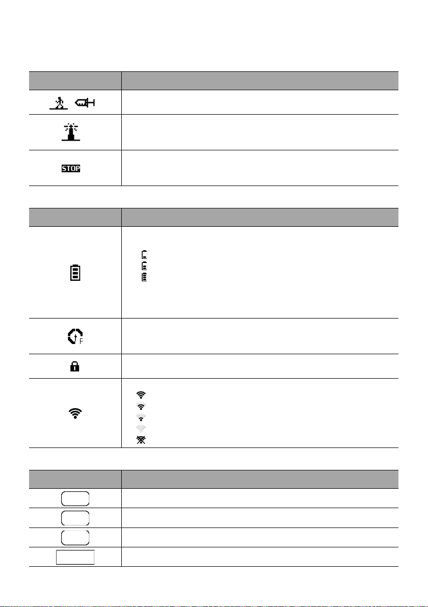
2.5.1 Infusion Status
Symbol Description
Infusion in Progress (Basic Profile)
Symbols for infusion in progress.
Infusion in Progress (Custom Profiles)
This symbol is displayed when the pump is infusing a drug customized with
infusion limits customized with a compatible DERS.
Infusion Stopped
STOP remains in the center of the screen until the user starts the infusion
again.
2.5.2 Screen Options
Symbol Description
Battery Logo
This symbol shows three different charge levels.
< 30 % battery charge
30 % - 70 % battery charge
> 70 % battery charge
If the ‘Battery logo’ option is enabled, this symbol is displayed constantly.
If the ‘Battery logo’ option is disabled, this symbol is only displayed when
the pump is operating on battery.
Pressure Logo
This symbol gives information about pump pressure settings and measured
pressure levels.
Keypad locked symbol
This symbol informs the user that the keypad is locked.
Wi-Fi module status
The Wi-Fi signal strength is high.
The Wi-Fi signal strength is medium.
The Wi-Fi signal strength is low.
No Wi-Fi signal (the Wi-Fi module is activated).
The Wi-Fi module is not activated.
2.5.3 Navigation Buttons
Symbol Description
Start
Confirm
Access Function
Access Function and Clear Settings
17
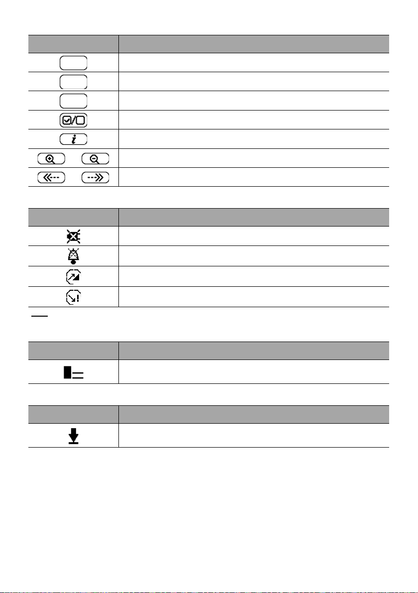
Symbol Description
exit
C
prog
Exit Function
Change Selection
Program Function
Select / Unselect
See More Information
/
/
Zoom in / Zoom out
Move the Event Marker to the Left / Right
2.5.4 Alarms and Safety Features
Symbol Description
Power Disconnection
Alarm Silenced
Pressure Increase
Drop in Pressure
Note
: For more information on alarms, see section 11, page 81.
2.5.5 Infusion Features
Symbol Description
Loading Dose
This symbol is displayed when programming a loading dose.
2.5.6 Data Communication
Symbol Description
Data Set Loaded
A new data set has been loaded to the pump.
18

2.6 Packaging
The Agilia SP MC packaging contains the following:
1 Agilia SP MC pump
User documents (Language: English)
1 Power cord
Packaging weight: Approximately 1.16 lb (530 g).
Packaging consists of: Recycled cardboard, expanded foam.
Information
It is the healthcare facility’s responsibility to check the pump
integrity upon receipt.
If the packaging contents are incomplete or damaged, contact
your Fresenius Kabi sales representative.
19

3 Fundamentals
3.1 Profiles
A profile defines the device configuration and drug library used for a group of
patients in a given healthcare environment.
By default, factory settings include only 1 profile (Basic Profile).
Custom profiles can be created and loaded to the pump using a compatible DERS.
Custom profiles feature a specific pump configuration and a drug library.
A pump can manage up to 20 profiles:
1 Basic Profile
Up to 19 custom profiles
Information
For pumps used on only one group of patients, we recommend disabling
the ability to select the profile, thus locking the pumps to the selected
profile.
3.1.1 Basic Profile
Basic Profile allows programming of an infusion for which settings have not been
pre-defined with a compatible DERS.
To program an infusion with Basic Profile, choose "Basic Profile" when selecting
a profile.
Basic Profile has the following characteristics:
The only infusion rate allowed is flow rate (mL/h).
The DERS's safeguards are unavailable:
- The infusion is programmed without drug names.
- Limits on drug infusion rates are not included.
Configurations and settings accessible in Basic Profile may not be suitable for all
patient groups and protocols.
3.1.2 Custom Profiles
Custom profiles can be created and uploaded to the pump using a compatible
DERS.
A custom profile contains the following:
a specific device configuration (pump settings that control the
mechanical functions of the pump such as alarm volume, and so on)
a drug library (optional), see section 3.2, page 21.
Depending on the way it is pre-configured with the medication safety software, a
custom profile may or may not include all of the functionalities described in this
IFU.
20

Information
We recommend using a custom profile when infusing critical
drugs.
We recommend that you create and upload profiles in order to
limit usage errors, and to better adapt the use of the pump to the
local practices of the different care units. For example, make sure
to limit flow rates for sensitive populations.
We recommend creating a specific profile per patient population
and/or care unit, therapy, protocol, and so on.
3.2 Drug Libraries
A drug library is a comprehensive list of drugs that includes limits on drug infusion
rates.
Information
Each drug library can support up to 150 drug entries that are
defined and validated by healthcare professionals according to
the drug protocols used at the healthcare facility and/or ward
level.
Drug settings may be adjusted on the pump according to pre-
defined programming limits, such as dose limits.
Infusion modes defined in a custom drug entry are not adjustable
on the pump.
3.3 Drugs
3.3.1 Infusion Rates
A drug in a drug library must specify the infusion rate:
Flow rate: Infusion of a volume over a period of time
Dose rate: Infusion of a specific amount of a drug corresponding to a dose
rate
3.3.2 Drug X (mL/h)
Drug X (mL/h) is an open entry that can be selected if the intended drug is not
found in the drug library. It has the following characteristics:
Fewer limits than the other drugs in the library.
A full complement of the medication safety software's safeguards is
unavailable.
It is strongly recommended to use Drug X (mL/h) in a limited number of clinical
cases and under close patient monitoring by the clinical staff.
In each custom profile, the healthcare facility can enable or disable Drug X (mL/h)
using the medication safety software.
21
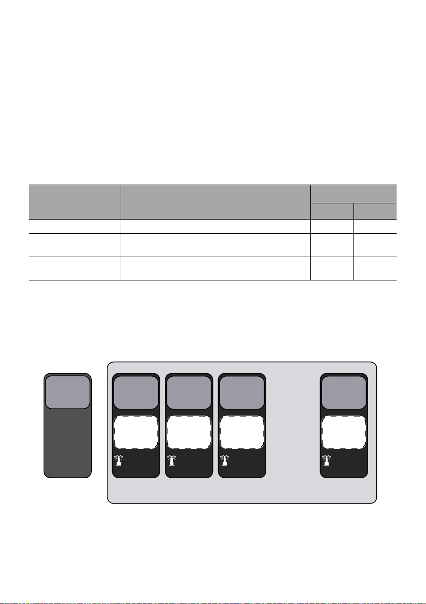
3.3.3 Hard Limits and Soft Limits
. . .
Device
Configuration
(factory)
Device
Configuration
2
Device
Configuration
3
Device
Configuration
4
Device
Configuration
20
Drug Library
B
Drug Library
A
Drug Library
C
Drug Library
S
Data Set
Profile 1
(Basic)
Profile 2
(Custom)
Profile 3
(Custom)
Profile 4
(Custom)
Profile 20
(Custom)
Programming limits can be set for each drug in a drug library. Two types of limits
can be set:
Hard limits: limits that cannot be overridden when programming an
infusion.
Soft limits: limits that can be overridden within an authorized range when
programming an infusion. An additional confirmation will be required.
3.3.4 Infusion Modes
An infusion can be started according to the following modes:
Infusion Mode Description
Infusion Rate
Flow Rate Dose Rate
Simple Rate Infusion with a programmed rate
Volume/Time
Dose/Time
Volume Limit
Infusion of a programmed volume or dose over a
programmed period of time
Infusion with a limitation on the volume or dose to
be infused
3.4 Data Set
A data set can contain up to 19 custom profiles that can be uploaded to Agilia
pumps with a compatible DERS.
If there is no data set uploaded to the pump, the pump can be used with the Basic
Profile.
22
4 Installation
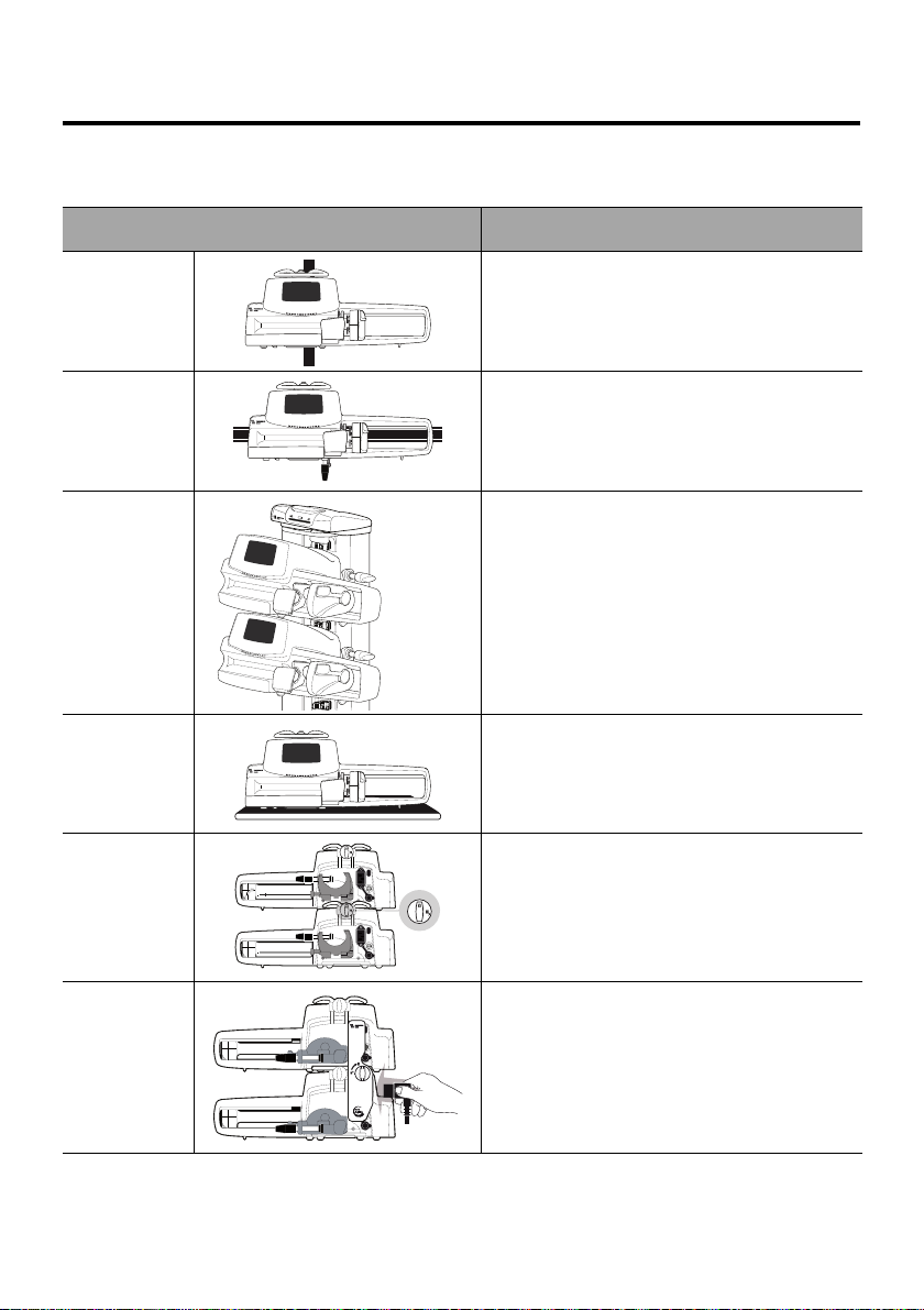
4.1 Types of Installations
A pump can be installed on any of the following:
Location Comments
See section 4.3.1, page 25.
On a Pole
On a Rail
On the
Agilia Link
Rack
On a Table
On Another
Pump
Pole specifications:
Diameter: from 0.6 to 1.6 in (15 to 40 mm)
See section 4.3.2, page 25.
Rail specifications:
Height: from 1.0 to 1.4 in (25 to 35 mm)
Depth: from 0.3 to 0.4 in (8 to 10 mm)
Refer to the Agilia Link accompanying
documents.
See section 4.3.3, page 26.
Only install a pump on a table if it is not
possible to attach it to a pole, a rail or
recommended Agilia accessory.
See section 4.3.4, page 26.
Refer to the Agilia Duo accompanying
documents.
On an Agilia
Duo
Do not use accessories that appear to be damaged. For more information on
accessories, refer to their respective accompanying documents.
23
Warning
3
2
1
1
1
2
3
The pump must be used in a horizontal and stable position to
function properly.
Use recommended Agilia accessories to ensure stability and
prevent the pump from falling. Do not stack the pump with
equipment other than those recommended.
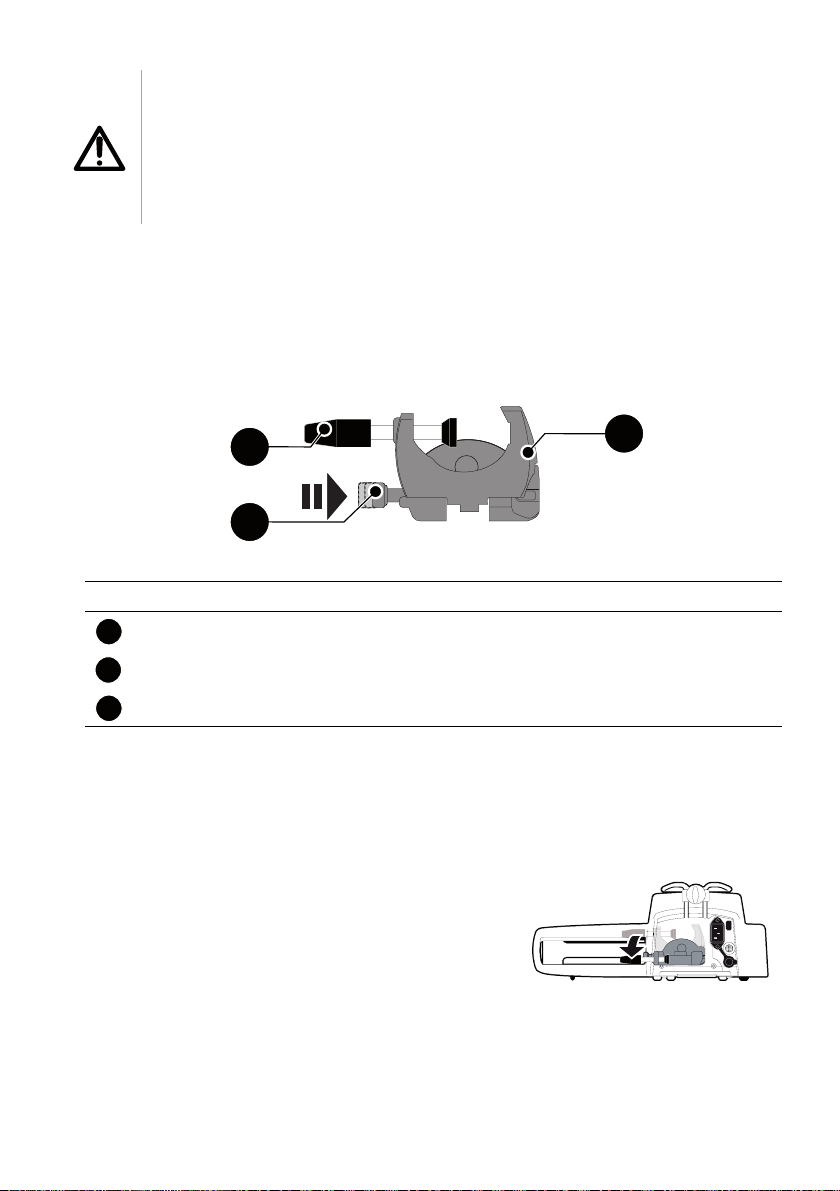
4.2 Using the Rotating Pole Clamp
The rotating pole clamp is located at the back of the pump.
When installing the pump on a pole or a rail, fasten the rotating pole clamp firmly
to avoid any movement of the pump.
4.2.1 Rotating Pole Clamp Description
Figure 4.1: Rotating Pole Clamp System
Legend
Screw Clamp
Release Button
Rotating Pole Clamp
4.2.2 Using the Rotating Pole Clamp
You can secure the rotating pole clamp vertically or horizontally by folding it
outward until the release button clicks into the locked position.
4.2.2.1 Folding the Clamp Down (outward)
You can fold the clamp down as follows:
1. Push the release button.
2. Fold the clamp outward.
24
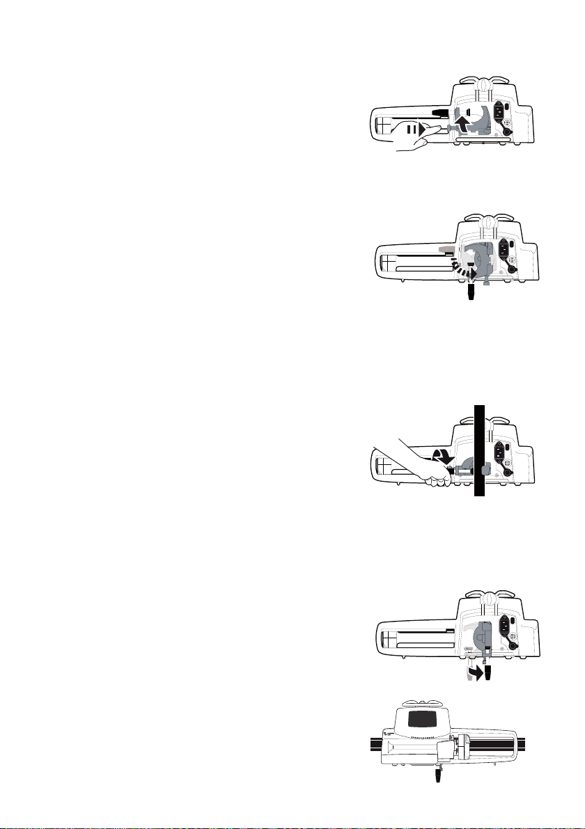
4.2.2.2 Folding the Clamp Up (inward toward the pump)
You can fold the clamp up as follows:
1. Push the release button.
2. Fold the pole clamp inward toward the pump.
4.2.2.3 Rotating the Clamp
You can rotate the clamp as follows:
1. Fold the clamp up (see above).
2. Rotate the clamp to a vertical position.
3. If necessary, fold the clamp outward (see
above).
4.3 Attaching the pump(s)
4.3.1 Attaching to a Pole
1. Fold the pole clamp down to the horizontal position:
see section 4.2.2.1, page 24.
2. Unscrew the clamp, attach to the pole, and
screw the clamp until the pump is fully secured
to the pole.
3. Make sure that the pump is securely attached.
For more information on installing the pump on a
pole, consult the pole’s Instructions for Use.
4.3.2 Attaching to a Rail
Only single pumps can be attached to a bed rail or gurney rail.
1. Rotate the pole clamp to the vertical position: see section 4.2.2.3, page 25.
2. Unscrew the clamp, attach to the rail, and screw
the clamp until pump is fully secured to the rail.
3. Make sure that the pump is securely attached.
25
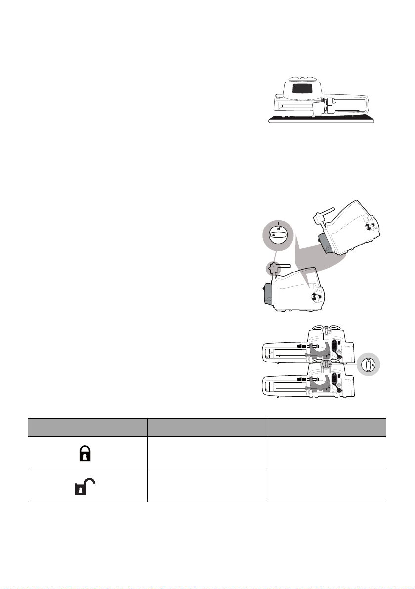
4.3.3 Using on a Flat Table
1. Fold the pole clamp up: see section 4.2.2.2, page 25.
2. Place the pump far enough from the table's
edges to prevent it from accidentally being
pushed off.
4.3.4 Attaching Two Pumps Together
You can attach two pumps together either for transport, or before fixing them to a
pole.
1. Fold both pumps’ pole clamps up: see section
4.2.2.2, page 25.
2. Slide the slot on the bottom of the upper pump
onto the handle of the lower pump.
3. Turn the attachment lock knob on the lower
pump handle clockwise until the locked symbol
lines up with the marker.
4. Make sure the two pumps are securely
attached together.
5. If needed, fold the two pole clamps down and
secure them tightly to the pole.
Symbol Location Description
Attachment Lock Knob Locked Position
Attachment Lock Knob Unlocked Position
26
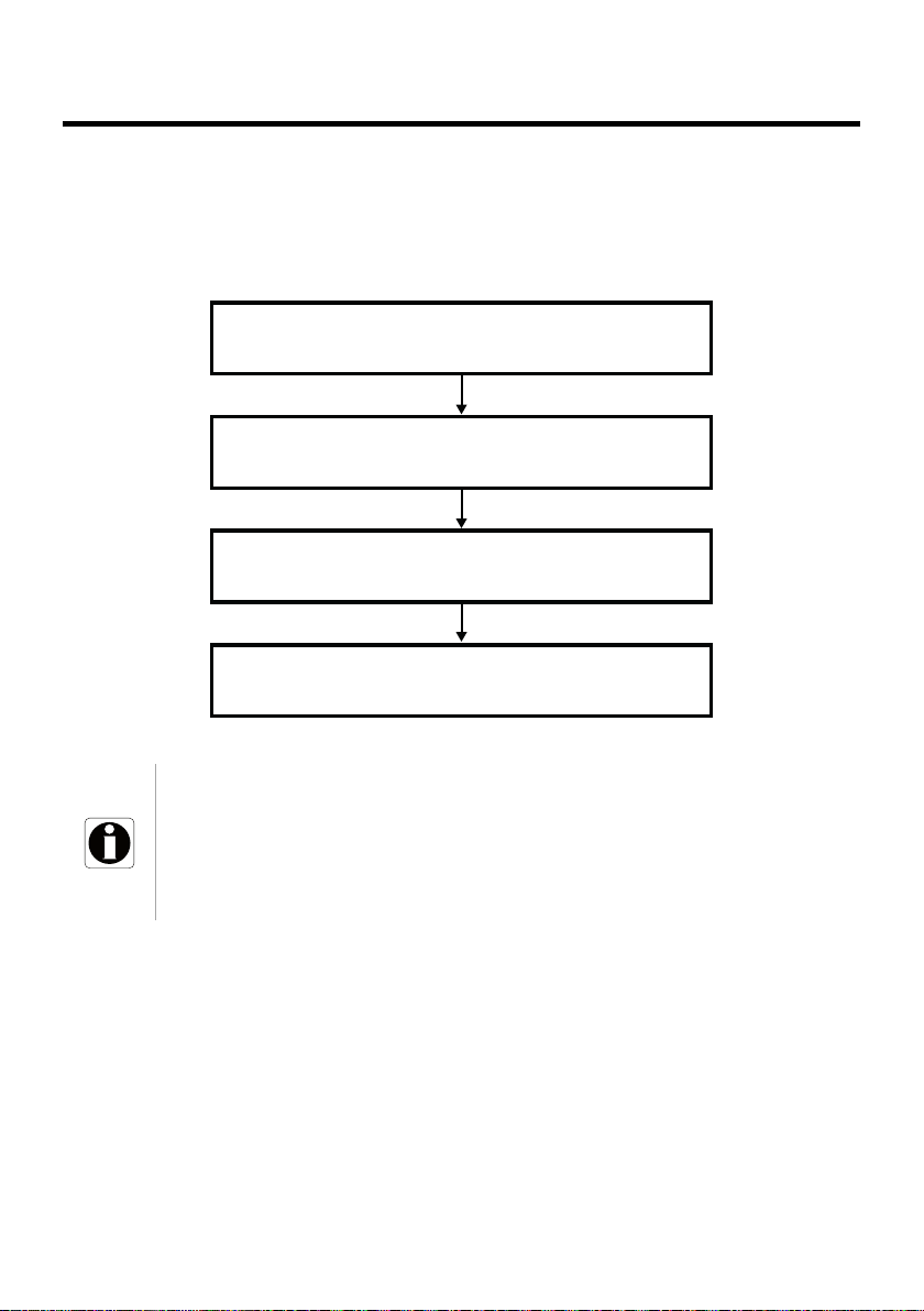
5 Getting Started
Preparing and priming the syringe and the extension set
Section 12.2, page 87.
Powering on
Section 5.3, page 28.
Installing the syringe
Section 5.4, page 30.
Programming an infusion
Section 6.5, page 35.
5.1 Flowchart
Once the pump is installed at the bedside, you must follow the steps below in order
to install a syringe and power on the pump.
Information
In order to ensure that all the safety features of the device are activated,
make sure that the following instructions are applied:
The pump is powered on prior to being connected to the patient.
The pump is not connected to the patient during the set-up.
27

5.2 Using the Pump for the First Time
1. Make sure the pump is correctly installed at the bedside.
See section 4, page 23.
2. Plug the pump into the AC power supply.
See section 16.1, page 103.
3. Before starting the pump for the first time, you must charge the battery for
approximately 6 hours.
Wait until the pump is fully charged.
Do not use the pump during the first charge.
4. Power on the pump.
See section 5.3, page 28.
5. Install a syringe into the pump.
See section 5.4, page 30.
5.3 Powering on
Information
The pump can operate using the battery; however, we
recommend that the pump be connected to a power supply as
often as possible during use in order to ensure that the battery
remains charged.
When the pump is connected to the power supply, check that the
power supply indicator lights up green, and that the power
cord and the wall plug are accessible.
1. Press .
An auto-test checks the functionality of the pump.
2. Immediately after powering on the pump, make sure that all LED lights blink.
3. Acknowledge the different screens listed in the table below.
28

Screen After Powering on Description
Startup screen: the following information is
displayed:
Product name / Ward name
Wi-Fi module status
Date & time
The pump is operating on battery.
The symbol shows three different charge
levels:
< 30 % battery charge
30 % - 70 % battery charge
> 70 % battery charge
No syringe is installed on the pump.
Syringe installation !!! is displayed on
top of the screen.
Install a syringe.
See section 5.4, page 30.
Maintenance reminder message (optional).
Same infusion screen (optional).
Press Yes to keep previous infusion settings.
Profile confirmation screen (optional).
Press Ok to confirm the profile.
: This screen is linked to the "same infusion"
Note
function above.
29
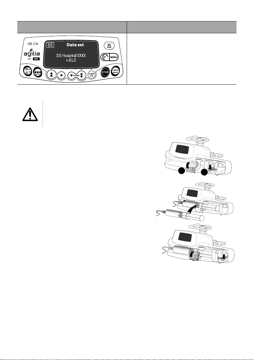
Screen After Powering on Description
A
B
Data Set information (optional)
5.4 Installing a Syringe
Warning
This must only be done when the patient is not connected.
1. Open the syringe barrel clasp [A].
2. Push the disengagement lever [B] down and
move the plunger driver to the right.
3. Place the syringe in its cradle, with the flanges
correctly inserted in the provided slot.
4. Secure the syringe with the syringe barrel
clasp [A].
5. Push the disengagement lever [B] and move
the plunger driver gently to the left until it is in
contact with the plunger head.
6. Check the general installation.
30
 Loading...